


REVERSE AIR - MODEL SWF
DUST COLLECTOR BAGHOUSE
INSTRUCTION, OPERATIONS &
MAINTENANCE MANUAL
CAMCORP, INC.
Phone: 913-831-0740 Fax: 913-831-9271

TABLE OF CONTENTS
OPERATING PRINCIPLE & SECTION/PARTS DETAIL........................................... 1-1
RECEIVING & INSPECTION OF UNIT.......................................................................2-1
ON SITE STORAGE RECOMMENDATIONS.............................................................3-1
SETTING UP YOUR UNIT............................................................................................4-1
BAG & CAGE INSTALLATION................................................................................... 5-1
START-UP CHECK LIST .............................................................................................. 6-1
START-UP DUST CONTROL SYSTEMS.................................................................... 7-1
SHUTDOWN PROCEDURES........................................................................................ 8-1
TROUBLE SHOOTING THE DUST COLLECTOR.....................................................9-1
TOUBLESHOOTING THE CLEANING MECHANISM............................................ 10-1
SAFETY RECOMMENDATIONS...............................................................................11-1
ROUTINE MAINTENANCE........................................................................................ 12-1
COMPONENT IOM MANUALS.................................................................................13-1
CAMCORP, INC.
Phone: 913-831-0740 Fax: 913-831-9271

OPERATION PRINCIPLE
A. Solids laden air or gases enter the unit at the hopper or housing inlet.
B. Air passes through the filter media.
C. Solids are retained on the filter media surface.
D. Cleaning consists of a rotating sweep arm with nozzles positioned over the bags
that continuously blows a reverse flow of air into the bags.
1. This momentarily takes a row of bags off stream through pressure reversal.
2. Flexing filter bags.
3. Solids are released to fall towards hopper and through rotary valve or other
discharge equipment.
CAMCORP, INC.
Phone: 913-831
1-1
-0740 Fax: 913-831-9271
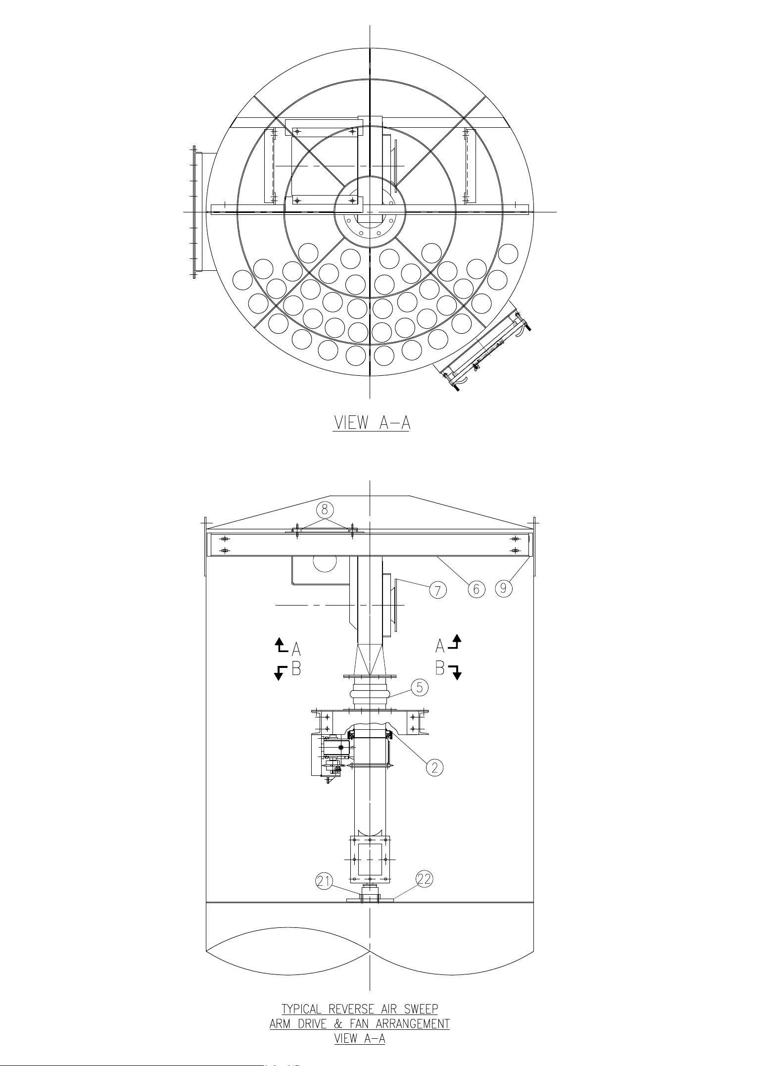

Camcorp Reverse Air Components
Item Quantity Description
1A
1B
2
3
4
5
6
7
8
9
10
11
12
13
14
15
16
17
18
19
20
21
22
1 Sweep Arm (Size Determined by Unit)
1 Sweep Arm (Size Determined by Unit)
1 8” OD Rotary Spool Section
1 8” OD Arm Rotation Support
1 8” OD Fan Exhaust Air Stub
1 8” Straight Rubber Hump
1 Fan Channel Support
1 Reverse Air Fan (Size Determined by Unit Size)
4 Vibration Isolation Supports
2 Fan Support Wall Bracket
4 Drive Mount Table Wall Brackets
2 Drive Mount Table Support Channel
1 50TTA2635 x 1” Sprocket & TTA35BS x 1 “ Torque Limiter Clutch
1 50A58 Drive Sprocket
1 Roller Chain Tensioner
1 206 Gearbox Drive Shaft
3 Motor, ½ HP, TEFC 1,800 RPM, 56C, 208-230/460/3/60
1 Primary Gear Reducer, 133Q56R20, 20:1 Ratio
1 Secondary Gear Reducer, 206Q56L40, 40:1 Ratio
1 Bracket Kit, 206S-BK (Secondary Reducer)
1 Drive Mount Support Table
1 4-Bolt Flange Thrust Bearing, 1 ½”
1 Bearing Mounting Plate
Visit our Website at: www.camcorpinc.com
Phone 913-831-0740 iFax 913-831-9271
CAMCORP, INC.


RECEIVING YOUR UNIT
Prior to accepting shipment, care must be taken to inspect all equipment received both for
proper count and for damage. Any and all irregularities must be noted on the carriers’
copy of the shipping receipt to assist in settling any claims for damage or shortages. All
equipment is shipped FOB point of origin whether on a prepaid or collect freight basis.
ANY CLAIM FOR DAMAGE IN TRANSIT OR SHORTAGES MUST BE
BROUGHT AGAINST THE CARRIER BY THE PURCHASER.
Once your claim has been filed with the carrier contact CAMCORP to notify us of the
problem(s), and then we will advise the appropriate repair procedure or recommend it to
be returned to the factory depending on the extent of damage.
INSPECTION OF UNIT
Housing: Particular attention should be paid to the sheet metal housing of your collector.
The unit should be inspected for dents, cracks, or rips. A dented housing may seriously
affect the structural integrity of the unit. If any of these signs are present, note them on
the shipping receipt and notify CAMCORP immediately. The entire unit should be
checked against the certified drawings for correctness and the manufacturer notified
immediately if there are any discrepancies. No corrections may be made without the
expressed written consent of the manufacturer.
Components: A count should be made of all pieces received and this should be verified
against the carrier’s manifest. Boxes should be inspected for rough handling, which may
have resulted in hidden damage.
2-1
Phone: 91
CAMCORP, INC.
3-831-0740 Fax: 913-831-9271

ON SITE STORAGE RECOMMENDATIONS
I. Baghouse and Housing
1. Housing can be stored outside.
2. Equipment must be blacked up to keep the flanges out of the dirt.
3. Many units are supplied with a plain finish bare steel interior. If storage of
more than two week is anticipated, the interior should be prime coated before
storage.
4. Covering the unit with a tarp is recommended to keep the interior from rusting
or corroding as well as keeping the finish in new condition. However, the tarp
is not absolutely necessary.
II. Bags & Cages
1. Bags must be stored inside a cool dry area protected from rodents and insects.
2. For extended storage the boxes for the bags should be wrapped with plastic
wrap or stretch wrap to protect from moisture.
3. If the bags get wet for any reason, immediately lay them out with adequate
ventilation to dry in order to prevent mold and mildew.
4. It is recommended to store the cages inside a dry area if at all possible.
5. If an inside location is not available, cages can be stored outside as long as they
are covered by a tarp.
6. Cages are generally stored horizontally on pallets to keep off the ground.
7. If cages can be stored horizontally, do not stack over three boxes high.
8. If the job site is in an area that may receive a significant snow load, the cages
must be stored vertically in order to prevent being crushed by the weight of the
snow. Do not stack more than one box high.
III. Accessory Parts
1. This includes all gauges, bag clamps, nylon or copper tubing, gaskets, and other
ports not specifically called out.
2. These items should be stored inside a cool dry place protected from insects and
rodents.
3-1
CAMCORP, INC.
Phone:
913-831-0740 Fax: 913-831-9271

ON SITE STORAGE RECOMMENDATIONS (continued)
IV. Fan and Fan Accessories
1. Fans can be stored outside on a pallet or skid to keep out of water and dirt.
2. Equipment should be covered with a tarp to protect from the bags.
3. Fan silencers, outlet dampers, and inlet boxes should also be tarped and stored
on a pallet or skid.
V. Ducting
1. Ducting can be stored outside on a pallet or skid to keep it off the ground. It
should be positioned so that water does not sit in the equipment.
2. If ducting is unpainted steel, it should be at least primed coated before storage.
3. If ducting is already finish coated, it should be tarped to protect the finish but is
not absolutely necessary.
VI. Knife Gate
1. All limit switches, solenoids, and air cylinder ports must be capped and taped to
prevent any moisture or dirt from entering.
2. Equipment can sit outside provided it is covered with a tarp and is on a pallet or
skid to keep it out of the water and dirt.
VII. Isolation Dampers
1. All limit switches, solenoids, and air cylinder ports must be capped and taped to
prevent any moisture or dirt from entering.
2. Equipment can sit outside provided it is covered with a tarp and is on a pallet or
skid to keep it out of the water and dirt.
VIII. Rotary Valve
1. Rotor and interior of valve should be well oiled with vegetable
oil to prevent
rust and to maintain compatibility with product.
2. Unit can be stored outside provided it is covered with a tarp and is on a pallet or
skid to keep it out of the water and dirt.
3-2
CAMCORP, INC.
Phone: 913-831-0740 Fax: 913-831-9271

ON SITE STORAGE RECOMMENDATIONS (continued)
IX. Butterfly (Wafer Valve)
1. All limit switches, solenoids, and air cylinder ports must be capped and taped to
prevent any moisture or dirt from entering.
2. Unit can be stored outside provided it is covered with a tarp and is on a pallet or
skid to keep it out of the water and dirt and sunlight.
X. Level Indicators
Store these items inside a cool dry area protected from rodents
XI. AC Inverters
Store these items and all other electrical controls inside a cool dry area protected
from rodents.
Phone: 913-8
3-3
CAMCORP, INC.
31-0740 Fax: 913-831-9271

SETTING UP YOUR UNIT
CAMCORP dust collectors are shipped in various states of assembly depending on the
size and configuration of the unit. Before attempting to move the dust collector or any of
its sections, review both the certified general assembly drawing supplied with your unit
and the rigging and lifting guidelines included in this manual. Become familiar with the
size and number of sections to be assembled, the orientation of inlet(s), outlet(s), access
door(s), and fan as well as the number and location of lifting lugs.
Dust collectors of this type are manufactured from steel sheets and are quite flexible.
Therefore, even though care has been taken to maintain dimensional accuracy and
squareness, some difficulty should be anticipated, and temporary bracing in the field may
be required.
Rigging and Lifting Guidelines
1. Do not lift the dust collector by any attachments other than the lifting lugs
provided.
2. Use all of the lifting lugs provided on the dust collector, or a section of the
dust collector, when making a lift.
3. If the lifting lugs are located below the roof line of the dust collector or
below the top of the section of the dust collector, a vertical pull must be made
to avoid crushing the top of the unit. Use spreader beams to accomplish this
vertical pull.
4. Attach tag lines at several locations to be able to control the unit when lifted
and to prevent spinning or swinging.
5. The dust collector should be lifted and lowered at a slow, uniform rate and
not allowed to bounce or joggle since this can cause excessive impact
stresses at the lift points.
Doors and Flanges: Hold-downs on doors should only be hand tightened. Excessive
pressure can distort the door panel itself resulting in leakage. All bolts on flanges should
be tight. All holes in the dust collector must be plugged prior to start-up if not being
connected.
4-1
CAMCORP, INC.
Phone: 913-831-0740 Fax: 913-831-9271

Platform Installation: The platform, ladder, handrail, and bracing are to be installed as
shown on the special platform detail provided. Use the part ID’s to locate the parts in the
proper location.
Explosion Vents (where applicable):
1. Figure 6 – The explosion vents are attached with a minimum of standard
steel fasteners for shipment. THESE MUST BE REMOVED and the
PVC Bolts installed that are included in the shipment. Extreme care should
be exercised when installing the PVC Bolts as they are very fragile. A
gasket is factory installed that will provide a seal between the vent panel
and the frame. DO NOT use silicone sealer or any other sealer or adhesive
at this joint as this will prevent the vent from operating properly.
2. The area around the vents should be clear of any personnel or obstructions
to prevent injury or damage.
Electrical: A 120 volt 60 Hertz circuit is required to operate the dust collector’s ½ HP
swep arm drive motor. A 230/460V 3 phase circuit is required to run the reverse air fan.
Gauges: Check the pressure differential gauge to make sure that the high-pressure tap is
connected below the tube sheet and the low-pressure tap is connected above the tube
sheet. Verify that the gauge have been zeroed prior to connection when it is in its
permanent mounting position.
Auxiliary Equipment: All auxiliary equipment must be installed according to its
manufacturer’s specifications and interlocked with the entire system as needed. Direction
of rotation of each item must be checked prior to start-up of the entire system.
4-2
Phone: 9
CAMCORP, INC.
13-831-0740 Fax: 913-831-9271

TOP LOAD BAG AND CAGE INSTALLATION
1. Inspect the cage for any signs of damage, warping, bent wires, or missing
welds.
2. Inspect the filter bag for any signs of mold, mildew, ripped seams, or holes.
3. Lower the closed end of the bag through the hole in the tube sheet.
4. With your hands, “kidney shape” the snap band bag top in order to fit and
align it within the tube sheet hole.
5. Fit the groove of the snap band to the I.D. of the tube sheet hole and allow it
to expand and audibly snap into place. If the band will not snap into place
initially, do not push on the “dimple” as doing this will permanently damage
the snap band. Instead, kidney shape the snap band from the opposite side of
the band. Then you can allow the band to expand and audibly snap into
place.
6. Check the fit of the snap band to the tube sheet. It should be even in height
above the tube sheet around the entire circumference, which will confirm to
the installer that the tube sheet is centered and well secured into the middle
groove of the snap band.
7. Lower the cage into the bag and press that cage top down into the bag’s snap
band I.D. When in position, the rolled flange of the cage top will rest on the
tube sheet and the bag and cage assembly will be rigidly mated. The O.D. of
the cage top provides a compression fit to the I.D. of the snap band.
8. Disconnect the drive chain to allow the sweep arm to rotate freely to access
the holes under the sweep arm if necessary.
9. Replace access doors and tighten accordingly. You are ready to begin startup procedures if all other preceding tasks and hook-ups are completed.
Phone: 913-8
5-1
CAMCORP, INC.
31-0740 Fax: 913-831-9271

PRODUCT HIGHLIGHT
BEADED SNAPBAND FILTER BAG DESIGN FOR FLAT TUBESHEET HOLE
The snapband was developed to improve sealing efficiency. This design eliminates multiple parts, minimizing labor
expenses. Camcorp provides a uniform double beaded gasket in the cuff assembly. This assures a leakproof seal for flat
plate tubesheet holes. When installing the bags, follow instructions provided.
PROPERINSTALLATIONOFTHECUFF
1. Form the snapband into the shape of a kidney.
The vertical seam in the cuff should be on the
outer radius of the kidney shape.
2. Seat the seam of the cuff into the hole first with
the tubesheet fitting between the beads, with
one above and one below it .
3. Release the band and it will spring securely into
place. Use caution, and ensure all fingers are
out of the tubesheet opening when the snapband is released. Make sure the snapband fits
squarely in the hole and there are no kinks in
the metal band.
NOTE:If you are converting to a snapband bag from some other type of sealing method, the tubesheet holes must
be inspected carefully to ensure that proper sealing will result. The surface finish on the inside diameter must be
relatively smooth. Any deep grooves or protrusions will cause leakage. Ahole that was flame cut, but not ground
smooth is one example. The tubesheet holes must be consistent in circumference from one hole to another.
If the circumference difference is determined by measuring, the holes should be checked to the nearest 0.001 in.
Slight out-of-roundness is acceptable. Take three measurements for each hole and record the average of these three
measurements. Compare all the hole averages. The difference between the largest average and smallest average hole
size should not exceed 0.020 in. Try sample cuff in largest and smallest hole to confirm proper fit.
When checking the sample snapband in the hole for fit, push on the edge of the snapband slightly with your thumb
to try and move it inward. If a gap occurs easily between the snapband and the edge of the tubesheet hole, leakage
may result. If the inside surface of the hole is smooth, check the cuff fit by trying to spin the cuff in the hole. If it
spins easily, it may leak.
Flat Plate Tubesheet Hole
Snapband
Top View
Seam

START-UP CHECKLIST
1. Installation
Make sure the unit is secured to grade. The ladder(s) and platform(s) must be
tightened and set up according to OSHA requirements. Ducting and piping must
be secured and routed out of the way of traffic whenever possible to avoid injury.
Ducting must also be free of all debris including moisture.
2. Interior of the dirty air plenum
A. Make sure that the filter bag assemblies hang straight and the bottoms do not
touch each other or any part of the collector interior. If this occurs, the bags
will have holes worn in them wherever they contact and will require
replacement.
B. High-level alarms should be connected sufficiently below the air inlet(s) to
avoid a plugged up inlet or blinded off filter bags.
3. Clean air plenum
A. All bolts on the flanges must be in place and properly tighten.
B. Verify that the reverse air fan and sweep arm drive are properly installed.
4. Exterior of dust collector
A. Access doors, inspection ports, and relief vents should seat effectively to
prevent leakage.
B. All bolts must be properly tightened.
C. Operate any equipment connected to the dust discharge of the dust collector.
Check the rotation of any motor driven equipment such as rotary airlocks,
horizontal unloading valves, live bottom bin activators, and screw conveyors.
Check slide gates and butterfly valves for binding.
5. Explosion relief panels – shear bolt style (where applicable)
A. Inspect for broken or missing bolts.
Phone: 913-8
6-1
CAMCORP, INC.
31-0740 Fax: 913-831-9271

START-UP DUST CONTROL SYSTEMS
1. Fan or blower system
A. Start the fan or blower and check rotation.
B. Check dust pickup points for proper suction; balance airflow in individual
ducts.
C. Check for air leakage at all flanged connections.
2. Equipment start-up sequence
A. Start the sweep arm drive motor. The sweep arm should rotate CCW when
viewed from above. An arrow noting the rotation direction is located on the
vertical air pipe.
B. Start the reverse air fan motor and check for CW rotation of the wheel (as
viewed from the motor side of the fan or CCW as viewed from the fan inlet).
This is CRITICAL to the proper cleaning of the bags. Air will exit the
nozzles regardless of direction, but will not be sufficient to clean unless the
fan wheel is rotating the correct direction.
C. Dust take away equipment such as rotary airlocks, screw conveyors,
horizontal unloading valves, live bottom bin activators, and pneumatic
conveying systems can now be started in their correct sequence.
D. Check that all access doors, hatches, ports, and other openings are closed and
latched or bolted.
E. The main exhaust fan can now be started and brought up to speed.
F. Start the dust laden air through the collector. The collector should be started
under partial load to allow the bags to become slowly and evenly coated with
dust particles.
On pneumatic conveying systems, watch the differential pressure gauge
closely for the first hour or so. If unstable, the collector discharge system
may be too small for the volume it is seeing. A quick fix is to reduce the
material feed until the discharge rate can be increased.
Phone:
7-1
CAMCORP, INC.
913-831-0740 Fax: 913-831-9271

G. Observe the manometer or magnahelic differential pressure gauge reading.
As the new filter bags become coated with dust, the efficiency of the filtering
action increases, and the differential pressure across the filter bags will also
increase. Slowly bring the collector to full load and note the final pressure
drop across the filter bags. Never allow the pressure drop across the filter
bags to exceed 17” w.g. maximum or filter bags may collapse.
H. Check the main airflow with a pitot tube, or equivalent measuring device, to
establish initial conditions. If the main airflow must be adjusted up or down
to suit the process, repeat step 2-H above.
Phone:
7-2
CAMCORP, INC.
913-831-0740 Fax: 913-831-9271

SHUT-DOWN PROCEDURES
1. Dust control systems
Reverse start-up procedure, shut down fan, then after 5 or 10 minute delay, shut
down the reverse air fan and sweep arm drive motor.
2. Pneumatic systems
Reverse start-up procedure, shut down fan, then after 5 or 10 minute delay, shut
down the reverse air fan and sweep arm drive motor.
Phone:
8-1
CAMCORP, INC.
913-831-0740 Fax: 913-831-9271

TROUBLESHOOTING THE DUST COLLECTOR
I. Excessive pressure drop across filter bags
The differential pressure gauge or manometer on your dust collector should read
6” w.g. or less. Higher readings and/or steadily increasing readings are an
indication that the main airflow through the dust collector may be restricted, and
a potential process problem such as poor suction at duct pickup points may
exist. In extreme cases (over 17” w.g.) filter bags will be damaged. Check the
following:
A. Pressure Gauge
Check the differential pressure gauge or manometer and the tubing leading
to the dust collector for proper operation. Disconnect the lines at the gauge
or manometer and clear with compressed air. Look for loose fittings,
cracked, broken, or pinched tubing. Make sure the gauge is zeroed or that
the manometer is level, zeroed and contains the correct fluid.
B. Bags Loaded with Dust
If the cleaning system is not operating properly refer to the section titled
“Troubleshooting the Cleaning System”.
A condition known as blinding. If the dust is dry, see paragraph
1-4; if the dust is wet, see paragraphs 5 and 6.
1. Dust Not Discharging from the Hopper
Check hopper for over-loading or bridging across the dust discharge.
Correct by repairing dust discharge equipment, replacing with higher
capacity equipment, or installing hopper vibrators, etc. as required to
keep the hopper clear.
2. Air Flow too High
If the main airflow is too high to allow dust to drop off of the filter bags,
an excessive pressure drop across the dust collector will result and dust
will build up in the system. In many cases this high pressure drop in
turn leads to a reduction in the main air flow so that it is necessary to
remove the dust accumulation from the filter bags (and the rest of the
system) before measuring the main air flow volume.
Phone: 913-8
9-1
CAMCORP, INC.
31-0740 Fax: 913-831-9271

TROUBLESHOOTING THE DUST COLLECTOR (continued)
Visually inspect the bags for heavy caking; if caking is evident, see the
note below and take the necessary action to clean the bags. Next,
measure the main airflow with a pitot tube or equivalent devise and
compare with the original volume for which the unit was designed. If
the flow is too high, cut back the main fan to prevent a recurrence of the
problem.
3. Particle Size and Dust Load
If possible, compare the dust particle size and loading with the original
design specifications. Finer dust may cause a higher pressure drop. Do
not hesitate to call the factory; we have experience with many kinds of
dust.
4. Bags Too Tight
Bags that have shrunk on their cages may not flex sufficiently during the
compressed air pulse to loosen caked dust. If the bags were cleaned or
laundered, pull a bag tight around its cage; you should be able to
“gather” a small fold of material between your fingers.
5. Water Leaks
Inspect the dust collector housing and ductwork for holes, cracks, or
loose gasketing where water could enter the collector.
6. Condensation
If moisture has been condensing inside the collector, check the dew
point temperature of the incoming air stream. If may be necessary to
insulate the collector and/or the ductwork leading to the collector to keep
surface temperatures above the dew point and prevent condensation of
the filter bags.
NOTE: Collectors that have had blinded or caked bags can possible be
put into service by running the pulsing air system for 15 to 30 minutes
with a 10 second timer “off time” and without the main fan or blower. If
the pressure drop is not lower when the main fan is started again, take
the bags out of the collector and remove the caked dust by special drycleaning. Make sure the timer “off time” has been reset to specifications
prior to re-start. Information pertaining to filter bag cleaning may be
obtained by calling your CAMCORP sales representative.
9-2
CAMCORP, INC.
Phone: 913-831-0740 Fax: 913-831-9271

TROUBLESHOOTING THE DUST COLLECTOR (continued)
II. Extremely Low Pressure Drop
A. Pressure Gauge
Check the differential pressure gauge or manometer and the tubing leading
to the dust collector as in I-A of this section.
B. Holes in Filter Bags or Bags Incorrectly Installed.
Inspect the filter bags for holes, rips, tears, or excessive wear. Make sure
that the filter bags were installed correctly according to the “Bag & Cage
Installation” section.
C. Ductwork and Dampers
Inspect the ductwork to and from the dust collector for air leaks or blockage.
Make sure that any dampers in the system are correctly positioned to allow
air to flow through the dust collector.
D. Leaks in the Housing
Check the tube sheets (flat steel sheets from which the filter bags are
suspended) and the dust collector housing for holes, cracks or loose
gasketing that would permit air to bypass the dust collector or filter bags.
III. Continuous Flow of Dust in the Clean Air Exhaust (Primary Dusting)
A. Holes in the Filter Bags or Bags Incorrectly Installed
Inspect the filter bags as in II-B this section.
B. Holes in the Tube Sheets
Check the tube sheets for holes, cracks, or loose bolts that would permit
dusty air to bypass the filter bags.
IV. Puff of dust in the clean air exhaust after each pulse (secondary dusting)
A. Worn filter bags
Inspect the filter bags for wear. Thin bags may not stop fine dust when
flexed by a compressed air pulse.
9-3
CLEAN AIR MANAGEMENT COMPANY, INC.
8224 Nieman Road i Lenexa, Kansas 66214 Phone: 913-831-0740 Fax: 913-831-9271

TROUBLESHOOTING THE DUST COLLECTOR (continued)
B. Residual Dust
If dust has gotten into the clean air plenum because of a dropped or torn bag,
hole in tube sheet, etc., the reverse air may stir up the dust and allow it to
escape into the clean air exhaust. Residual dust may also be driven down
inside the filter bags by the reverse air; if the filter bags are filled with
several inches of dust, clean both the clean air plenum and the filter bags to
avoid further problems.
V. Short Filter Bag Life
This is often a complicated problem to diagnose and we recommend calling the
factory for advice. The following list may be helpful in performing some
preliminary check:
A. Temperature
Operating Temperature above the recommended limit of the filter bag
material (220 degrees F max.)
B. Chemical Attack
Bag material degrades due to attack from certain chemicals in the dust or
gasses in the air stream.
C. High Moisture
High moisture content in the collector may cause certain filter bag material
to shrink or degrade (more rapidly at elevated temperatures).
D. Localized abrasion
Abrasion of the bags at the dusty air inlet; a dust impingement baffle may be
required.
E. Internal Bag Supports Gone Bad
Corroded, rusted or broken filter cages can cause excessive bag wear.
Stainless steel or coated cages are available.
Phone: 913-8
9-4
CAMCORP, INC.
31-0740 Fax: 913-831-9271

TROUBLESHOOTING THE CLEANING MECHANISM
1. Fan - If the fan is not operating properly please refer to the New York Blower
manual located in this IOM manual. Verify rotation direction of fan wheel – CCW
as viewed from the fan inlet.
2. Sweep Arm Drive – Motor not rotating.
A. Remove the motor from the gear drive and check for proper operation. If
the motor does not rotate, repair or replace.
B. If the motor does rotate properly check for binding or roughness in the
gear drive. Repair or replace one or both gear boxes as necessary.
3. Sweep Arm Drive – Motor rotating and sweep arm not rotating or rotating
intermittently.
A. Enter the clean air plenum and check for obstructions in the path of the
rotating sweep arm. Remove any obstructions
B. Verify that the sweep arm is rotating parallel to the tubesheet and that the
nozzles do not strike the cage tops and cause the sweep arm to stop. If this
is not the case call the factory.
C. Verify that all rows have a cleaning nozzle above them to provide
complete cleaning.
D. Verify that the torque limiting clutch on the small sprocket is slipping.
E. Verify that the chain is not binding. If it is then check the sprocket
alignment.
F. Disconnect the drive chain. The sweep arm should rotate freely and with
no binding or roughness. If binding is experienced grease the rotary union.
If the binding or roughness continues inspect the bearing and replace if
necessary.
Phone:
10-1
CAMCORP, INC.
913-831-0740 Fax: 913-831-9271

SAFETY RECOMMENDATIONS
Because this unit may be under pressure, do not attempt to open any device doors or
panels while fans or blowers are running.
If your unit is equipped with a discharge auger or an airlock, be sure chain guards are
installed before start-up and servicing is attempted only after electrical power is locked
out.
While servicing the filter, it is very important that there are no open flames, welding or
grinding sparks. Dust laden air could be highly explosive and extreme care must be
taken.
Before entering any dust collector:
1. Run cleaning mechanism 20 minutes with the fan off to clean filter bags.
2. Discharge solids from hopper.
3. Lock out electrical power on all rotating equipment.
4. On toxic operation, purge collector housing and install a blank in the inlet
duct.
5. Install catwalks and safety cables.
6. Secure access doors in an open position or remove doors.
7. Use buddy system.
8. Wear a respirator.
9. Use common sense.
11
-1
CAMCORP, INC.
Phone: 913-831-0740 Fax: 913-831-9271

ROUTINE MAINTENANCE
A. Inspection
Frequency will vary as widely as there are operating conditions. In general
proceed as follows:
1. Daily – Check unit differential pressure.
2. Weekly – Verify that the sweep arm drive and reverse air fan are operating
properly.
3. Monthly – Lubricate fan, rotary valve and screw conveyor. Check seals on
latter two for dust loss.
4. Quarterly – On Top Access Units, check for dust accumulation in clean air
plenum.
B. Repairs
1. Filter bags – Generally replacement, although some applications can be
laundered.
2. Rotary Valves – Usually a matter of periodic seal and blade replacement.
More detailed information is supplied with the valve.
3. Screw Conveyors – Periodic replacement of “V” belts and shaft seals.
Inspect hanger bearings during filter bag change. Failure will be detected by
the squeal.
4. Fans – “V” belt tension and replacement of bearings if running rough.
Make sure rotor balance is maintained.
12
-1
CAMCORP, INC.
Phone: 913-831-0740 Fax: 913-831-9271

®
MAINTENANCE INSTRUCTIONS
FOR WORM GEAR
SPEED REDUCERS
Emerson Power Transmission
P O Box 687
MAYSVILLE, KY 41056
Phone: 800-626-2093
www.emerson-ept.com
F O R M
8721
March 2003
Center Distances
1.33, 1.54, 1.75, 2.06, 2.37, 2.62, 3.00, 3.25
3.75, 4.50, 5.16 and 6.00
™

wercspaC
eziS
euqroT
)sbL.tF(
02-4/152.6
81-61/531
61-8/302
41-61/753
31-2/105
11-8/509
INTRODUCTION
The following instructions apply to RAIDER® Worm Gear Speed Reducers. When ordering parts or requesting information
be sure to provide all the data stamped on the reducer nameplate.
EQUIPMENT REQUIRED
In addition to standard Mechanic's tools, the following equipment is required: arbor press, wheel puller, torque wrench,
dial indicator, seal driver, bluing, adhesive sealant, snap ring pliers for internal and external rings.
GENERAL INSTRUCTIONS
Housings - Clean external surfaces of reducer before removing seal cages and end covers to
prevent dirt from falling into the unit. Record mounting dimensions of accessories for reference
when reassembling. If it is necessary to remove the reducer from its operating area, disconnect
CAPSCREW
TIGHTENING
TORQUES
all connected equipment and lift reducer from its foundation.
Seals - Replacement of all seals is recommended when a unit is disassembled. However, if seals
are not to be replaced, protect seal lips by wrapping shaft with plastic tape coated with oil or
grease before removing or replacing seal cage assembly. Clean the shaft but do not use any
abrasive material on the shaft surface polished by the seal.
CAUTION
If the reducer is painted, extreme care should be taken to mask the shaft
extensions and rubber surface of the seals. Paint on the shaft adjacent to the
Table 1
seal or on the seal lip will cause oil leakage.
TO CHANGE OUTPUT SHAFT DIRECTION
To change the hand of a unit from left hand to right hand, or vice versa, the following instructions apply:
1. Remove drain plug and drain oil from unit.
2. Remove end cover and seal cage capscrews; then while supporting output shaft remove end cover and shims from
the unit. (The shims may be between the seal cage/end cover and housing, or between the bearing outer race and
seal cage/end cover - do not remove the bearing race unless it is to be replaced).
3. Remove output shaft and seal cage together from extension side.
NOTE: Keep all shims with their respective seal cage and end cover.
4. Reassemble unit per instructions later in this manual.
UNIT DISASSEMBLY
1. Remove drain plug and drain oil from unit.
2. Low speed shaft (gear shaft) removal:
A. Remove end cover and seal cage capscrews.
B. With a firm hold on the output extension remove end cover and shims (The shims may be between the seal cage/
end cover and housing, or between the bearing outer race and seal cage/end cover - do not remove the bearing
race unless it is to be replaced).
C. Carefully slide output shaft assembly and seal cage out extension side.
D. Slide seal cage off low speed shaft using caution to prevent damage to seal lips.
E. Wire or tie the shims to their mating end cover and seal cages. (This only applied if the shims are between the
seal cage/end cover and housing). They will be available for reference when assembling the unit. Some units
are factory assembled with internal shims so this note may not apply.
!
WARNING
High voltage and rotating parts may cause
serious or fatal injury.
Turn off power to install or service.
Operate with guards in place.
Read and follow all instructions in this manual.
2
Disconnect all before adjusting units
© Emerson Power Transmission Manufacturing, L.P. or affiliates 2003. All Rights Reserved.
3. High speed shaft (worm shaft) removal:
C-Flange units
1.33 C.D. through 3.25 C.D.:
Use a small chisel to make a groove in the stamped steel cover opposite the motor flange. Pry off the cover. Remove
internal snap ring from housing bore. Remove motor flange. Using a plastic hammer, gently tap on the motor end of the
shaft to feed worm shaft assembly through housing and out.
3.75 C.D. through 6.00 C.D.:
Remove motor flange. Remove seal cage opposite motor face. Keep shims with seal cage for reassembly. Remove bearing
nut and washers from end opposite motor. Using a plastic hammer, gently tap the shaft on the motor end. Push shaft
assembly through housing until rear bearing outer race is free. Slide bearing inner-races off the shaft and remove worm
through front of housing. If a press is available, pressing the shaft out is preferable.
Basic units
1.33 C.D. through 3.25 C.D.:
Use a small chisel to make a groove in the stamped steel cover opposite the motor flange. Pry off the cover. Remove
internal snap ring from housing bore. Remove motor flange. Using a plastic hammer, gently tap on the extension end of
the shaft, to feed worm shaft assembly through housing and out. On units with C.D. of 1.33, 1.54, 2.63, and 3.00, front
bearing will remain in housing bore. Use soft tool and plastic hammer to tap bearing out extension end of housing from
rear. Be sure to tap on outer-race of bearing. If a press is available, pressing this bearing out is preferable.
3.75 C.D. through 6.00 C.D.:
Remove front and rear seal cages. Keep shims with seal cages for reassembly. Remove bearing nut and washers from
end opposite extension. Using a plastic hammer, gently tap the shaft on extension end. Push shaft assembly through
housing until rear bearing outer-race is free. Slide bearing inner-races off shaft. Reverse direction and push shaft through
extension end of housing and out. If a press is available, pressing the shaft out is preferable.
PARTS SERVICE
1. Housing – Clean inside of housing with kerosene or solvent and then dry.
2. Seal cages and end cover – Remove dirt from joint faces, wipe clean and dry.
3. Air vent – Wash in kerosene, blow clean and dry.
4. Seals – To replace seals without dismantling reducer refer to steps C through F below. To replace seals when the
entire reducer is dismantled and coupling hubs, sprockets, pulleys, pinions, keys, etc. have been removed the
following instructions apply:
Note: Replacement of all seals is recommended when a unit is disassembled. New seals will leak if the seal lips
are damaged or if seal’s rubbing surface on the shaft has been altered. Protect seal lips at all times. Clean the shaft
but do not use any abrasive material on the shaft surface polished by the seal.
A. Block up seal cages and press or drive out seal.
B. Remove old sealing compound from seal seat in cage if it is present. If a seal with rubber coating on the outside
diameter is used, no sealant is necessary. If no rubber coating is on seal outside diameter, coat seal cage bore
with adhesive sealant immediately before assembly.
To prevent possible damage to seal lips, do not reassemble seals until high speed and low speed shafts have
been reassembled to the housing. Then see steps E and F below.
C. See Figures 1 through 4 – To replace seals without dismantling reducer, proceed as follows:
Do not damage shaft; new seals will leak if seal contacting surface is marred. Use punch and place two or more
holes in steel casing of seal, Figure 1. (The steel casing may be rubber coated) Insert sheet metal screws, leaving
the heads sufficiently exposed so they can be pried up or grasped with pliers, Figure 2. Do not drill holes because
chips may get into the unit.
Sheet Metal Screws
Disconnect all power before adjusting units
© Emerson Power Transmission Manufacturing, L.P. or affiliates 2003. All Rights Reserved.
Figure 3 Figure 4Figure 1 Figure 2
3

D. Work seal loose. Be careful to keep all metal or dirt particles from entering unit. Remove old sealing compound
from seal seat if it is present. Also remove burrs and sharp edges from shaft. Clean with rag moistened with solvent.
Do not use abrasive material on shaft seal contacting surface.
E. Protect seal lips when handling; seal leakage will result if these are damaged. If a seal with rubber coating
on the outside diameter (O.D.) is used, no sealant is necessary. If no rubber coating is on seal O.D., coat
seal cage bore with adhesive sealant. Coat seal lips with oil and carefully work seal into position. Before
sliding seal into position, protect seal lips from shaft keyway edges by wrapping shaft with plastic tape coated
with oil. Position garter spring toward the inside of the unit. Place a square faced pipe or tube against the seal
O.D. and drive or press seal until fully seated as shown in Figure 3. Do not strike seal directly.
F. For best performance, seat the seal square with shaft within .005" at 180°. Check with dial indicator as shown
in Figure 4, Page 3, or with a straight edge and feelers, or square and feelers. To straighten a cocked seal, place
tubing over the seal and tap the tube lightly at a point diametrically opposite the low point on the seal. Do Not
strike seal directly.
5. Bearings –
A. Wash all bearings per bearing manufacturers recommendations and then dry.
B. Inspect bearings carefully and replace those that are worn or questionable.
Note: Replacement of all bearings is recommended.
C. Use a wheel puller or press to remove worm shaft bearings. Apply force to inner race only – not to cage or outer
race.
D. Use a wheel puller or press to remove taper bearing inner races.
E. To replace tapered bearing inner races and all ball bearings, heat bearings in an oil bath or oven to maximum
of 290° F (143° C). Slide high speed shaft bearings onto the oiled shaft until seated against the shoulder or snap
ring of the shaft. Slide low speed shaft bearing onto the oiled shaft against the gear spacer.
F. Thoroughly coat all bearings with lubrication oil.
6. Worm, gear and shafts
A. Worm and high speed shaft – since all worms are integral with the high speed shaft, any wear or damage to the
worm will necessitate replacing both.
B. Press shaft out of bronze worm gear. To reassemble gear and low speed shaft, freeze shaft or heat gear. Do
not exceed 200° F (93° C). Insert key into the shaft keyway and press shaft into oiled gear bore.
Note: It is advisable to replace both the worm and worm gear should either of the assemblies require
replacement.
UNIT REASSEMBLY
1. Preliminary
A. Check to see that all worn parts have been replaced, gear and bearings coated with oil and all parts cleaned.
Remove all foreign matter from unit feet. The feet must be flat and square with each other.
B. Before starting to reassemble reducer, clean old shims or replace with new shims of equal thickness.
2. High Speed Shaft (Worm Shaft) Assembly
C-Flange units
1.33 C.D. through 3.25 C.D.:
Lubricate Bearing Bores of Housing. Press bearing onto end of worm shaft flush to shoulder (or snap ring). Lock bearing
onto shaft with external snap ring. Insert shaft assembly from opposite motor end into housing until seated against shoulder
in bore. Lock shaft assembly into housing bore with internal snap ring. Coat outside diameter of stamped steel end cover
with adhesive sealant (except, if end cover is rubber coated DO NOT use sealant) and press into input bore opposite motor
flange until flush with housing.
C-Flange units
3.75 C.D. through 6.00 C.D.:
Apply adhesive sealant to both housing input faces. Sub-assemble the two bearing inner-races onto rear of worm shaft
and secure with lock nut and washers. Insert shaft assembly into rear bore of housing along with the first bearing outerrace. With plastic hammer gently tap end of shaft until bearing outer-race is seated against shoulder in housing bore. If
a press is available, pressing the assemble in is preferable. Press the final bearing outer race in and install the rear seal
cage. Adjust end play per instructions below (Item 3C). Install motor flange.
Basic units
1.75 , 2.06, 2.37 and 3.25 C.D.:
Disconnect all power before adjusting units
© Emerson Power Transmission Manufacturing, L.P. or affiliates 2003. All Rights Reserved.
4

Lubricate Bearing Bores of Housing. Sub-assemble the rear bearing onto worm shaft. Lock rear bearing onto shaft with
external snap ring. Insert shaft assembly from opposite extension end into housing until bearing is seated against shoulder
in bore. Lock shaft assembly in housing bore with internal snap ring. Coat outside diameter of stamped steel endcover with
adhesive sealant (except, if end cover is rubber coated DO NOT use sealant) and press into input bore opposite extension,
until flush with housing.
1.33 , 1.54, 2.62 and 3.00 C.D.:
Lubricate Bearing Bores of Housing. Sub-assemble the rear bearing onto worm shaft. Lock rear bearing onto shaft with
external snap ring. Insert shaft assembly from opposite extension end into housing until bearing is seated against shoulder
in bore. Lock shaft assembly in housing bore with internal snap ring. Press front bearing into extension side of housing
until seated against shoulder or snap ring on the worm shaft. Coat outside diameter of stamped steel endcover with
adhesive sealant (except, if end cover is rubber coated DO NOT use sealant) and press into input bore opposite extension,
until flush with housing.
3.75 through 6.00 C.D.:
Apply adhesive sealant to both housing input faces. Press extension side bearing inner-race onto worm shaft. Insert worm
shaft into extension side bore of housing. Hold worm shaft in place and slip bearing inner-race onto shaft until seated
against shoulder. Press rear bearing outer-race into housing bore opposite extension until seal cage can be installed. Install
seal cage. Adjust end play per instructions below (Item 3C).
3. Low Speed Shaft (Gear Shaft) Assembly
A. Determine output shaft direction.
B. Assemble low speed shaft assembly, seal cage, and end cover with shims on both seal cage and end cover.
Torque capscrews to torques listed in Table 1. Rotate the input shaft to seat output bearings.
C. Moving the shaft back and forth by hand, check axial float with dial indicator as shown in Figure 5. Axial float must
be .0005 - .003" with .0005 being the absolute minimum. Do not preload bearings. If the axial float is not as
specified, add or subtract required shims under end cover or behind bearing outer race, inside the cover,
depending on the unit.
D. Remove output shaft with seal cage and apply bluing to several teeth on the gear. Worm thread and gear teeth
must be clean of oil. Reassemble output shaft and seal cage with output key facing up.
E. Use a rag to apply hand pressure to the output shaft and rotate the high speed shaft both directions until the gear
teeth with bluing have gone through gear mesh several times. Return output shaft to original position. Remove
output shaft and seal cage to inspect contact. Compare with Figure 6. If contact is not correct, move assembly
in the direction shown in Figure 6 by adjusting the shims. Maintain the same total shim thickness so the bearing
end play is not affected. Repeat Steps D a E until contact pattern is acceptable.
F. Recheck axial float with dial indicator.
G. When contact pattern is correct, tighten seal cage and end cover capscrews to torques listed in Table 1.
Fig. 5
Disconnect all power before adjusting units
© Emerson Power Transmission Manufacturing, L.P. or affiliates 2003. All Rights Reserved.
5

4. Seals - To reassemble seals to unit, see Parts Service Steps on
Page 3.
5. Motorized Coupling Adapter
Reassemble using the original dimensions determined under "General
Instructions" on Page 2.
6. Final Inspection
A. Turn the gear train by hand as a final check.
B. Re-install reducer and accessories.
C. Fill reducer with the recommended oil to the appropriate level.
See the installation instructions supplied with the
reducer.
D. Spin test for three minutes and check for noise, leakage or rapid
temperature rise.
1/3
1/3
IDEAL
1/3
RUNS FROM
CENTER TOWARDS
LEAVING EDGE
Fig. 6a: Entering and Leaving Sides
1/6 OF FACEWIDTH
CLEAR ON
ENTERING SIDE
Fig. 6b: ACCEPTABLE
DOES NOT ENTER
CENTER THIRD
MOVE GEAR
MOVE GEAR
RUNS TO
ENTERING EDGE
Fig. 6c: UNACCEPTABLE
PREVENTATIVE MAINTENANCE
1. After first week, check all external capscrews and plugs for tightness.
2. Periodically, check oil level when gears are at rest. Add oil if needed. Do not fill above the recommended level because
leakage and overheating may result.
Printed in U.S.A.
6
Emerson Power Transmission
P.O. Box 687
Maysville, Kentucky 41056
TEL: 800-626-2093
© Emerson Power Transmission Manufacturing, L.P. or affiliates 2003. All Rights Reserved.

Martin
SPROCKET & GEAR, INC.
BULLETIN TL-1
TORQUE LIMITER CLUTCH
DRIVE OVERLOAD PROTECTION
Now in Stock at All
MartinFacilities
Also Stock Plate Sprockets Bored to
Size and Face Ground for Torque Limiters

MartinTORQUE-LIMITER
clutch offers thrifty overload protection
that’ s easy to adjust.
Here is low cost protection for your machinery . . . a torque
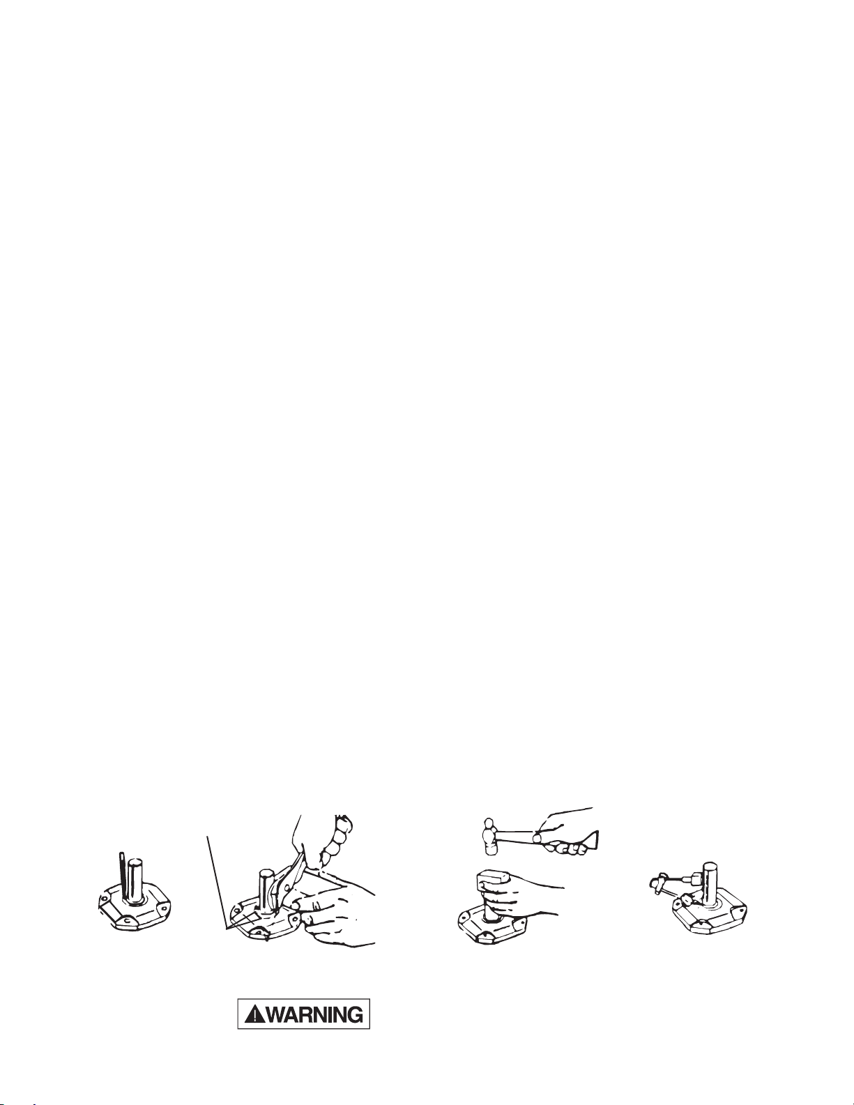
limiting clutch that is easy to install.
Torque-Limiter clutches feature an exclusive “Easy-Set
Adjustment.” With “Easy-Set,” torque adjustment is accomplished quickly! The need for hammer and block, brute
strength and spanner wrenches is eliminated.
These simple steps and the job is done:
1. Snug up the adjusting nut, finger tight, locate set screw
over nearest spline notch and tighten. See table at right.
2. Tighten three cap screws until heads bottom — with a
small wrench; this gives maximum torque.
3. For less torque — back off the cap screws, loosen the set
screw, back off adjusting nut to one of the six spline
notches as required, and retighten set screw and cap
screws.
“Easy-Set Adjustment” not only simplifies installation, it provides solid support for pressure plates by compression at
their peripheries.
The Torque-Limiter clutch gives machinery permanent prote c tion against overloads during starting, reversing or driving —
by slipping at any desired load. It resumes driving without
resetting when the overload is relieved. It is simple in
design, compact, efficient and built for long life. It provides
low cost torque limiting service for a wide variety of applications. No lubrication . . . minimum maintenance.
Starting shock from electric motors is a major cause of
maintenance of moving parts. Torque-Limiter clutches provide a cushion by slipping until the torque drops to a pre-set
level. They can be set to reduce shock loads on motors and
driven equipment during reversing or inching. They provide
mechanical protection against breakage due to sudden
overload — by slipping when the pre-set torque limit is
reached.
2
T orque-Limiter
Clutches
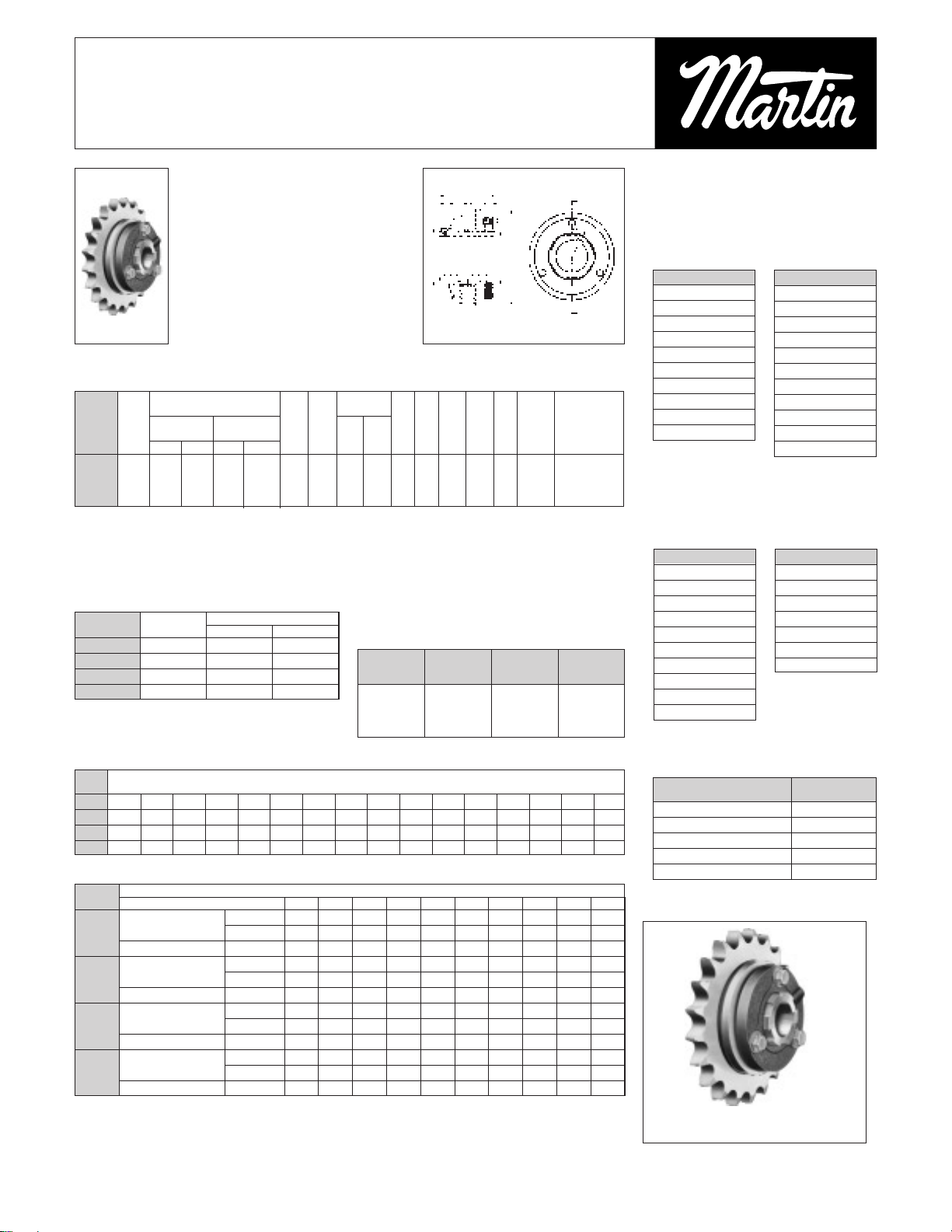
Torque-Limiter clutches may be used with a sprocket, gear,
sheave, flange or other driven member. It is recommended
that the rubbing sides of the driven member be ground to
provide a smooth rubbing surface of 65 to 125 micro-inches.
See torque rating table on following page.
The driven member is mounted on an oil-impregnated bushing and clamped between two, high quality friction discs by
spring pressure. Each Torque-Limiter unit, completely
assembled, contains one spring. Higher torque ratings can
be obtained by the use of a second spring nested within the
original spring. See rating table on following page.
When an overload occurs, the driven member slips between
long-life, clutch-type friction discs. After slipping has started,
it will continue at approximately 90% of the torque setting,
due to the lower coefficient of friction when slipping, until the
overload condition has been corrected.
TORQUE (lb.-ins.)
70-2
70-1
50-2
50-1
35-2
35-1
25-2
25-1
01234567
SPLINES
Note:
Graph indicates approximate rated torque vs number of
splines adjusting nut is backed off from finger tight.
TORQUE-LIMITER CLUTCH CALIBRATION
#25 300 700 400 1200
#35 600 1700 900 2500
#50 950 2650 2350 5700
#70 2000 8000 3100 11500
Torque Rating
One Spring Two Springs
Size Min. Max. Min. Max.
12000
11000
10000
9000
8000
7000
6000
5000
4000
3000
2000
1000
0
3
T orque-Limiter
Clutches
Stock Plate Sprockets with Ground
Face and Bored to Fit the Martin
T orque Limiter
Sprocket Size
35TTA25-25
35TTA26-25
40TTA20-25
40TTA22-25
40TTA24-25
40TTA28-25
40TTA30-25
50TTA17-25
50TTA21-25
50TTA22-25
Sprocket Size
35TTA35-35
35TTA40-35
40TTA28-35
40TTA30-35
40TTA32-35
50TTA22-35
50TTA24-35
50TTA25-35
50TTA26-35
60TTA18-35
60TTA20-35
TT25 1 300 700 400 1200 21⁄2 13⁄41⁄811⁄3229⁄6419⁄6419⁄64 21⁄2 11⁄2 1.368 1.631/1.628
TT35 2.5 600 1700 900 2500 3
1
⁄2 27⁄161⁄85⁄845⁄6423⁄6435⁄64 33⁄16 115⁄16 1.675 2.006/2.003
TT50 6 950 2650 2350 5700 5 2
7⁄81⁄85⁄853
⁄6429⁄6421⁄32 45⁄16 213⁄16 2.625 3.008/3.005
TT70 18 2100 8000 3100 11500 7 3
7⁄81
⁄4 11⁄455⁄6431⁄6429⁄32 6 4 3.811 4.197/4.194
Torque Rating ▲ CKL
(Pound-Inches) +.000 +.003
With One With Two –.002 –.000
Size Avg. Spring Springs** G Spline Spkt.
No. Wt.
Min. Max. Min. Max
A B Min. Max. D E
♦ H J O. D. Bore
T orque-Limiter Clutch Ratings
TT25
1
⁄2
7
⁄8 1
TT35
3
⁄4 13⁄16 11⁄4
TT50 1 13⁄4 2
TT70 13⁄8 23⁄4 3
Size Stock
Max. Bore
No. Bore Std. KW* Shallow KW*
1
⁄2-9⁄16
1
⁄8 ×1⁄16 17⁄16-13⁄4
3
⁄8 × 3⁄16
5
⁄8-7⁄8
3
⁄16 ×3⁄32 113⁄16-21⁄4
1
⁄2 ×1⁄4
15
⁄16-11⁄4
1
⁄4 ×1⁄8 25⁄16-23⁄4
5
⁄8 ×5⁄16
15⁄16-13⁄8
5
⁄16 ×5⁄32 313⁄16-3
3
⁄4 ×3⁄8
Torque- TorqueLimiter Limiter
Bore Keyway Bore Keyway
TT25 1⁄25⁄83⁄47⁄8
TT35
3⁄47
⁄8 1
TT50 1 11⁄8 13⁄16 11⁄4 13⁄8 17⁄16 11⁄2 15⁄8
TT70 17⁄16 11⁄2 13⁄4 115⁄16 2 27⁄16
Size
No. Finished Bores
STK. 25 19 19 16 .. .. .. .. .. ..
TT25 Min. Teeth MTO 25 19 19 16 .. .. .. .. .. ..
Bush. Lght. Req’d.
1
⁄8
1⁄81
⁄4
1
⁄4 .. .. .. .. .. ..
STK. 35 25 26 21 18 15 .. .. .. ..
TT35 Min. Teeth MTO 33 25 26 21 18 15 .. .. .. ..
Bush. Lght. Req’d.
1
⁄8
1⁄81
⁄4
1⁄43
⁄83⁄8 .. .. .. ..
STK. 48 35 35 29 25 19 .. .. .. ..
TT50 Min. Teeth MTO 46 35 35 29 25 19 .. .. .. ..
Bush. Lght. Req’d.
1
⁄8
1⁄81
⁄4
1⁄43
⁄83⁄8 .. .. .. ..
STK. .. .. 48 38 33 26 21 18 16 14
TT70 Min. Teeth MTO .. .. 48 38 33 26 21 18 16 14
Bush. Lght. Req’d. .. .. 1⁄4
1⁄43
⁄83⁄81⁄27⁄87⁄8 1
Unit
Min. Allowable Sprocket Teeth and Length of Bushing Req’d for Chain Number
Size Sprocket Pitch 35 41 40 50 60 80 100 120 140 160
★ Min. number of teeth on sprocket stocked by factory which can be used w/Torque-Limiter clutch.
Min. number of teeth on made-to-order sprocket which will permit chain to clear friction disc.
* Use one
3
⁄8″ long bushing and one 1⁄2″ long.
♦ Use two 1⁄2″ long bushings.
† KW Same as Std. Listed in Tables Above. Additional S.S. See List Price
Bored to Size T orque Limiters w/Std. KW & I-SS
†
† Additional SS See List Price Alterations
* KW To Be Cut Central w/Threaded Spline
Standard Keyways
Stock Bores — T orque Limiters (No KW I-SS
†
)
▲ Using a center member with rubbing sides ground
parallel — 65 to 125 micro-inches. Center member
must be clean and free from oil, rust, etc.
** Second spring may be nested in one originally fur-
nished. Order if required.
♦ Nominal for maximum torque setting. For minimum
torque setting, add
3
⁄64 for No. 25; 5⁄64 for No. 35; 3⁄32 for
Nos. 50 and 70. When two springs are used this
dimension is increased approximately
1
⁄16″ on Nos.
25, 35 and 50 —
3
⁄32″ on No. 70.
TORQUE-LIMITER CLUTCHES
Each assembled unit contains one
spring. Higher ratings can be obtained
by ordering a second spring to nest in
the original one. Bushings need to be
ordered separately if required.
The rubbing sides of the center
member should be ground parallel —
65 to 125 micro-inches.
Sprocket Size
40TTA35-50
50TTA30-50
50TTA32-50
60TTA25-50
60TTA26-50
60TTA28-50
60TTA30-50
80TTA20-50
80TTA22-50
80TTA24-50
Sprocket Size
60TTA36-70
80TTA26-70
80TTA28-70
80TTA30-70
80TTA36-70
100TTA22-70
100TTA24-70
PRESSURE PLATE 2
FRICTION DISC 2
ADJ. NUT ASSY. & S.S. 1
ADJ. TENSION NUT 3
HUB 1
TT25 TT50
TT35 TT70 QTY. REG.*
SPARE PARTS
UNIT TT25 UNIT TT35
UNIT TT50 UNIT TT70
* PER UNIT
B
GE
C
ED
JLK
A

7
Coupling
Safety
WARNING & SAFETY
REMINDER
Safety must be considered a basic factor in machinery operation at all times. Most accidents
are the result of carelessness or negligence. All rotating power transmission products are potentially dangerous and must be guarded by the contractor, installer, purchaser, owner, and user as
required by applicable laws, regulations, standards, and good safety practice. Additional specific information must be obtained from other sources including the latest editions of American
Society of Mechanical Engineers; Standard A.N.S.I. B15.1. A copy of this standard may be
obtained from the American Society of Mechanical Engineers at 345 East 47th Street, New
York, NY 10017 (212-705-7722).
It is the responsibility of the contractor, installer, purchaser, owner, and user to install, maintain, and operate the parts or components manufactured and supplied by Sprocket &
Gear, Inc., in such a manner as to comply with the Williams-Steiger Occupational Safety Act
and with all state and local laws, ordinances, regulations, and the American National Standard
Institute Safety Code.
Guards, access doors, and covers must be securely fastened before operating any equip-
ment.
If parts are to be inspected, cleaned, observed, or general maintenance performed,
the
motor driving the part or components is to be locked out electrically in such a manner
that it cannot be started by anyone,
however remote from the area. Failure to follow these
instructions may result in personal injury or property damage.
CAUTION
NOTE: CA TALOG DIMENSIONS
Every effort is made to keep all catalog dimensions and styles current in the catalog, however
from time to time, it is necessary because of manufacturing changes to alter stock products
dimensionally .
If any stock product dimension or style shown in this catalog is critical to your application
please consult factory for certification.
WARNING

A WORD ABOUT SAFETY
The above WARNING decal appears on all nyb fans. Air moving
equipment involves electrical wiring, moving parts, sound, and
air velocity or pressure which can create safety hazards if the
equipment is not properly installed, operated and maintained.
To minimize this danger, follow these instructions as well as the
additional instructions and warnings on the equipment itself.
All installers, operators and maintenance personnel should
study AMCAPublication 410, "Recommended Safety Practices
for Air Moving Devices", which is included as part of every shipment. Additional copies can be obtained by writing to New York
Blower Company, 7660 Quincy St., Willowbrook, IL60521.
ELECTRICAL DISCONNECTS
Every motor driven fan should have an independent disconnect
switch to isolate the unit from the electrical supply. It should be
near the fan and must be capable of being locked by maintenance personnel while servicing the unit, in accordance with
OSHA procedures.
MOVING PARTS
All moving parts must have guards to protect personnel. Safety
requirements vary , so the number and type of guards needed to
meet company, local and OSHA standards must be determined
and specified by the user. Never start a fan without having all
safety guards installed. Check regularly for damaged or missing
guards and do not operate any fan with guards removed. Fans
can also become dangerous because of potential “windmilling”,
even though all electrical power is disconnected. Always block
the rotating assembly before working on any moving parts.
SOUND
Some fans can generate sound that could be hazardous to
exposed personnel. It is the responsibility of the system
designer and user to determine sound levels of the system, the
degree of personnel exposure, and to comply with applicable
safety requirements to protect personnel from excessive noise.
Consult nyb for fan sound power level ratings.
AIR PRESSURE AND SUCTION
In addition to the normal dangers of rotating machinery, fans
present another hazard from the suction created at the fan inlet.
This suction can draw materials into the fan where they become
high velocity projectiles at the outlet. It can also be extremely
dangerous to persons in close proximity to the inlet, as the
forces involved can overcome the strength of most individuals.
Inlets and outlets that are not ducted should be screened to
prevent entry and discharge of solid objects.
ACCESS DOORS
The above DANGER decal is placed on all nyb cleanout doors.
These doors, as well as access doors to the duct system,
should never be opened while the fan is in operation. Serious
injury could result from the effects of air pressure or suction.
Bolted doors must have the door nuts or fasteners securely
tightened to prevent accidental or unauthorized opening.
RECEIVING AND INSPECTION
The fan and accessories should be inspected on receipt for any
shipping damage. Turn the wheel by hand to see that it rotates
freely and does not bind. If dampers or shutters are provided,
check these accessories for free operation of all moving parts.
F.O.B. factory shipping terms require that the receiver be
responsible for inspecting the equipment upon arrival. Note
damage or shortages on the Bill of Lading and file any claims
for damage or loss in transit. nyb will assist the customer as
much as possible; however, claims must be originated at the
point of delivery.
INSTALLATION
MAINTENANCE,
OPERATING
INSTRUCTIONS
PRESSURE BLOWERS
TYPE HP PRESSURE BLOWERS
IM-140
12345
THIS FAN HAS MOVING PARTS THAT CAN CAUSE
SERIOUS BODILY INJURY. BEFORE OPERATING
OR STARTING MAINTENANCE READ THE
INSTALLATION AND MAINTENANCE
INSTRUCTIONS AND THE AMCA SAFETY
PRACTICES MANUAL PROVIDED WITH THIS FAN.
DURING OPERATION
1. KEEP BODY, HANDS, AND FOREIGH OBJECTS
AWAY FROM THE INLET,THE OUTLET, AND THE
OTHER MOVING PARTS OF THE FAN SUCH AS
SHAFTS, BELTS, AND PULLEYS.
2. DO NOT OPERATE AT EXCESSIVE SPEEDS OR
TEMPERATURES.
BEFORE STARTING MAINTENANCE WORK:
LOCK POWER SUPPLY IN OFF POSITION AND
IMMOBILIZE FAN WHEEL.
98-0250
DO NOT OPEN UNTIL THE POWER
SUPPLY HAS BEEN LOCKED OFF
AND THE SHAFT HAS STOPPED
ROTATING.
FAILURE T O DO THIS CAN RESUL T
IN SERIOUS BODILY INJURY.
98-0249

HANDLING AND STORAGE
Fans should be lifted by the base, mounting supports, or lifting
eyes only. Never lift a fan by the wheel, shaft, motor, motor
bracket, housing inlet, outlet, or any fan part not designed for
lifting. Aspreader should always be used to avoid damage.
On a direct drive Arrangement 8 fan, lifting holes are provided
in the motor base to assist in handling the fan assembly. These
lifting holes should be used in conjunction with the lifting eyes
when lifting and positioning the fan onto its foundation. A heavy
round steel bar or appropriate fixture can be passed through the
lifting holes to simplify attachment of the lifting device. Be sure
to follow all local safety codes when moving heavy equipment.
Whenever possible, fans and accessories should be stored in a
clean, dry location to prevent rust and corrosion of steel components. If outdoor storage is necessary, protection should be
provided. Cover the inlet and outlet to prevent the accumulation
of dirt and moisture in the housing. Cover motors with waterproof material. Refer to the bearing section for further storage
instructions.
Check shutters for free operation and lubricate moving parts
prior to storage. Inspect the stored unit periodically. Rotate the
wheel by hand every two weeks to redistribute grease on
internal bearing parts.
FAN INSTALLATION
nyb wheels are dynamically balanced when fabricated.
Complete assembled fans are test run at operating speeds to
check the entire assembly for conformance to nyb vibration limits. Nevertheless, all units must be adequately supported for
smooth operation. Ductwork or stacks should be indepen-
dently supported as excess weight may distort the fan
housing and cause contact between moving parts. Where
vibration isolators are used, consult the nyb certified drawing
for proper location and adjustment.
Slab-Mounted Units
Acorrectly designed and level concrete foundation provides the
best means of installing floor-mounted fans. The mass of the
base must maintain the fan/driver alignment, absorb normal
vibration, and resist lateral loads. The overall dimensions of the
concrete base should extend at least six inches beyond the
base of the fan. The weight of the slab should be two to three
times the weight of the rotating assembly, including the motor.
The foundation requires firmly anchored fasteners such as the
anchor bolts shown in Figure 1.
Move the fan to the mounting location and lower it over the
anchor bolts, leveling the fan with shims around the bolts.
Fasten the fan securely. When grout is used, shim the fan at
least 3/4-inch from the concrete base. (See Figure 1.) When
isolation is used, check the nyb certified drawing for installation
instructions.
Elevated Units
When an elevated or suspended structural steel platform is
used, it must have sufficient bracing to support the unit load and
prevent side sway. The platform should be of welded construction to maintain permanent alignment of all members.
Figure 1
V-BELT DRIVE
Installation
1. Remove all foreign material from the fan and motor shafts.
Coat shafts with machine oil for easier mounting. Mount
the belt guard backplate at this time if partial installation is
required prior to sheave mounting.
2. Mount sheaves on shafts after checking sheave bores and
bushings for nicks or burrs. Avoid using force. If resistance
is encountered, lightly polish the shaft with emery cloth
until the sheave slides on freely. Tighten tapered bushing
bolts sequentially so that equal torque is applied to each.
3. Adjust the motor on its base to a position closest to the fan
shaft. Install belts by working each one over the sheave
grooves until all are in position. Never pry the belts into
place. On nyb packaged fans, sufficient motor adjustment
is provided for easy installation of the proper size belts.
4. Adjust sheaves and the motor shaft angle so that the
sheave faces are in the same plane. Check this by placing
a straightedge across the face of the sheaves. Any gap
between the edge and sheave faces indicates misalignment. Important: This method is only valid when the width
of the surface between the belt edge and the sheave face
is the same for both sheaves. When they are not equal, or
when using adjustable-pitch sheaves, adjust so that all
belts have approximately equal tension. Both shafts should
be at the right angles to the center belt.
Belt Tensioning
1. Check belt tension with a tensioning gage and adjust using
the motor slide base. Excess tension shortens bearing life
while insufficient tension shortens belt life, can reduce fan
performance and may cause vibration. The lowest allowable tension is that which prevents slippage under full load.
Belts may slip during start-up, but slipping should stop as
soon as the fan reaches full speed. For more precise tensioning methods, consult the drive manufacturer’s literature.
2. Recheck setscrews, rotate the drive by hand and check for
rubbing, then complete the installation of the belt guard.
Page 2

3. Belts tend to stretch somewhat after installation. Recheck
tension after several days of operation. Check sheave
alignment as well as setscrew and/or bushing bolt tightness.
COUPLING
Coupling alignment should be checked after installation and
prior to start up. Alignment is set at the factory, but shipping,
handling, and installation can cause misalignment. Also check
for proper coupling lubrication. For details on lubrication and
for alignment tolerances on the particular coupling supplied,
see the manufacturer's installation and maintenance supplement
in the shipping envelope.
Installation
Most nyb fans are shipped with the coupling installed. In cases
where the drive is assembled after shipping, install the coupling
as follows:
1. Remove all foreign material from fan and motor shafts and
coat with machine oil for easy mounting of coupling halves.
2. Mount the coupling halves on each shaft, setting the gap
between the faces specified by the manufacturer. Avoid
using force. If mounting difficulty is encountered, lightly
polish the shaft with emery cloth until the halves slide on
freely.
Alignment
1. Align the coupling to within the manufacturer's limits for
parallel and angular misalignment (see Figure 2). A dial
indicator or laser can also be used for alignment where
greater precision is desired. Adjustments should be made
by moving the motor to change shaft angle, and by the use
of foot shims to change motor shaft height. Do not move
the fan shaft or bearing.
2. When correctly aligned, install the flexible element and
tighten all fasteners in the coupling and motor base.
Lubricate the coupling if necessary.
3. Recheck alignment and gap after a short period of operation, and recheck the tightness of all fasteners in the coupling assembly.
Figure 2
START-UP
Safe operation and maintenance includes the selection and use
of appropriate safety accessories for the specific installation.
This is the responsibility of the system designer and requires
consideration of equipment location and accessibility as well as
adjacent components. All safety accessories must be installed
properly prior to start-up.
Safe operating speed is a function of system temperature and
wheel design. Do not under any circumstances exceed the
maximum safe fan speed published in the nyb engineering
supplement, which is available from your nyb field sales representative.
Procedure
1. If the drive components are not supplied by nyb, verify with
the manufacturer that the starting torque is adequate for
the speed and inertia of the fan.
2. Inspect the installation prior to starting the fan. Check for
any loose items or debris that could be drawn into the fan
or dislodged by the fan discharge. Check the interior of the
fan as well. Turn the wheel by hand to check for binding.
3. Check drive installation and belt tension.
4. Check the tightness of all setscrews, nuts and bolts. When
furnished, tighten hub setscrews with the wheel oriented
so that the setscrew is positioned underneath the shaft.
5. Install all remaining safety devices and guards. Verify that
the supply voltage is correct and wire the motor. “Bump”
the starter to check for proper wheel rotation.
6. Use extreme caution when testing the fan with ducting disconnected. Apply power and check for unusual sounds or
excessive vibration. If either exists, see the section on
Common Fan Problems. To avoid motor overload, do not
run the fan for more than a few seconds if ductwork is not
fully installed. On larger fans, normal operating speed may
not be obtained without motor overload unless ductwork is
attached. Check for correct fan speed and complete installation. Ductwork and guards must be fully installed for safety.
7. Setscrews should be rechecked after a few minutes, eight
hours and two weeks of operation (see Tables 1 & 2 for
correct tightening torques).
NOTE: Shut the fan down immediately if there is any sudden increase in fan vibration.
Page 3
BEFORE INITIAL OPERATION:
1. TIGHTEN ALL SET
SCREWS
IN FAN WHEEL.
2. TIGHTEN ALL SET
SCREWS
IN BEARINGS.
3. REPEAT AFTER 8 HOURS
OF OPERATION.
4. REPEAT AGAIN AFTER
TWO WEEKS OPERATION.
98-0271
Table 1 - WHEEL SETSCREW TORQUES
Setscrew Size Carbon Steel Setscrew Torque*
Diameter (in.) lb.-in. lb.-ft.
1/2 600 50
5/8 -- 97
3/4 -- 168
* Stainless Steel setscrews are not hardened and should
not be tightened to more than 1/2 the values shown.
Table 2 - BEARING SETSCREW TORQUE, lb.-in.
Setscrew Manufacturer
Diameter
Link-Belt Sealmaster SKF McGill Dodge
1/4 90 65 50 85 --
5/16 185 125 165 165 160
Note: Split pillow block bearings are fixed to the shaft with
tapered sleeves and generally do not have setscrews.
FAN MAINTENANCE
nyb fans are manufactured to high standards with quality mate-
rials and components. Proper maintenance will ensure a long
and trouble-free service life.
Do not attempt any maintenance on a fan unless the electrical supply has been completely disconnected and
locked. In many cases, a fan can windmill despite removal of
all electrical power. The rotating assembly should be blocked
securely before attempting maintenance of any kind.
The key to good fan maintenance is regular and systematic
inspection of all fan parts. Inspection frequency is determined
by the severity of the application and local conditions. Strict
adherence to an inspection schedule is essential.
Regular fan maintenance should include the following:
1. Check the fan wheel for any wear or corrosion, as either
can cause catastrophic failures. Check also for the buildup of material which can cause unbalance resulting in
vibration, bearing wear and serious safety hazards. Clean
or replace the wheel as required.
2. Check the V-belt drive for proper alignment and tension
(see section on V-belt drives). If belts are worn, replace
them as a set, matched to within manufacturer’s tolerances. Lubricate the coupling of direct-drive units and
check for alignment (see section on couplings).
3. Lubricate the bearings, but do not over lubricate (see the
bearing section for detailed specifications).
4. Ceramic-felt shaft seals require no maintenance, although
worn seals should be replaced. When lip-type shaft seals
are provided, lubricate them with "NEVER-SEEZ" or other
anti-seize compound.
5. During any routine maintenance, all setscrews and bolts
should be checked for tightness. See the table for correct
torques.
6. When installing a new wheel, the proper wheel-to-inlet
clearance must be maintained (see Figure 3 ).
WHEEL BALANCE
Airstreams containing particulate or chemicals can cause abrasion or corrosion of the fan parts. This wear is often uneven and
can lead to significant wheel unbalance over time. When such
wear is discovered, a decision must be made as to whether to
rebalance or replace the wheel.
The soundness of all parts should be determined if the original
thickness of components is reduced. Be sure there is no hidden
structural damage. The airstream components should also be
cleaned to remove any build-up of foreign material. Specialized
equipment can be used to rebalance a cleaned wheel that is
considered structurally sound.
Balance weights should be rigidly attached at a point that will
not interfere with the housing nor disrupt airflow. Remember
that centrifugal forces can be extremely high at the outer radius
of a fan wheel. Welding is the preferred method of balance
weight attachment. Be sure to ground the welder directly to the
fan wheel. Otherwise, the welding current could pass through
the fan bearings and damage them.
Figure 3
BEARINGS
Storage
Any stored bearing can be damaged by condensation caused
by temperature variations. Therefore, nyb fan bearings are
filled with grease at the factory to exclude air and moisture.
Such protection is adequate for shipment and subsequent
immediate installation.
For long term or outdoor storage, mounted bearings should be
regreased and wrapped with plastic for protection. Rotate the
fan wheel by hand at least every two weeks to redistribute
grease on internal bearing parts. Each month the bearings
should be purged with new grease to remove condensation,
since even a filled bearing can accumulate moisture. Use caution when purging, as excessive pressure can damage the
seals. Rotate the shaft while slowly adding grease.
Operation
Check the setscrew torque before start-up (see table for correct
values). Since bearings are completely filled with grease at the
factory, they may run at an elevated temperature during initial
operation. Surface temperatures may reach 180°F. and grease
may bleed from the bearing seals. This is normal and no
attempt should be made to replace lost grease. Bearing surface
temperatures will decrease when the internal grease quantity
reaches a normal operating level. Relubrication should follow
the recommended schedule.
Page 4
WHEEL-INLET CLEARANCE

COMMON FAN PROBLEMS
Lubrication
Use the table for relubrication scheduling according to operating speed and shaft diameter. Bearings should be lubricated
with a premium quality lithium-based grease conforming to
NLGI Grade 2. Examples are:
Mobil - Mobilith AW2 Chevron - Amolith #2
Texaco - Premium RB Shell - Alvania #2
These greases are for bearing surface temperatures of 40°F. to
180°F. For surface temperatures of 181°F. to 230°F. use
Mobilith SHC220.
Do not use “high temperature” greases, as many are not formulated to be compatible with fan bearings.
Add grease to the bearing while running the fan or rotating the
shaft by hand. Be sure all guards are in place if lubrication is
performed while the fan is operating. Add just enough grease to
cause a slight purging at the seals. Except on split pillowblocks.
Completely filled bearings will run hotter until a sufficient
amount of grease is purged out of the seals.
Split pillowblock bearings (Link-Belt P-LB6800 & P-LB6900,
SKF SAF 22500, Dodge SAF-XT) should be cleaned and
repacked at approximately every eighth lubrication interval.
This requires removal of the bearing cap. Clean out old grease
and repack the bearing with fresh grease. Pack the bearing fully
and fill the housing reservoir to the bottom of the shaft on both
sides of the bearing. Replace the bearing cap, being careful not
to mix caps as they are not interchangeable from one bearing
to another. Do not over lubricate.
BEARING LUBRICATION INTERVAL [months]
RPM 1 - 501- 1001- 1501- 2001- 2501- 3001- 3501-
Shaft 500 1000 1500 2000 2500 3000 3500 4000
6 6 5-6 4-6 4-6 3-5 2-4 2-4
1 7/16
64422111
6 6 4-6 4-6 2-4 2-4 2 1-2
1 11/16
6 4 2 1 1 1 1-2 1-2
2 3/16 6 4-6 4 2-4 2 -2 7/16 6 4-6 4 2-4 2 -2 15/16 4-6 4-6 2-4 2 1-2 --
Ball Bearings & Split Non- Split Pillowblock
Split Pillowblock Spherical Roller Bearings
Spherical Roler Bearings
NOTE:
1. These are general recommendations only; specific
manufacturer’s recommendations may vary slightly.
2. Assumes clean environment, -20°F. to 120°F.
a. Consult The New York Blower Company for
operation below -20°F. ambient.
b. Ambient temperatures greater than 120°F.
will shorten bearing life.
c. Under extremely dirty conditions, lubricate
more frequently.
3. Assumes horizontal mounting configuration. For vertically mounted applications, lubricate twice as frequently.
Excessive Vibration
A common complaint regarding industrial fans is “excessive
vibration”. nyb is careful to ensure that each unit is precisely
balanced prior to shipment; however, there are many other
causes of vibration including:
1. Loose mounting bolts, setscrews, bearings or couplings.
2. Misalignment or excessive wear of couplings or bearings.
3. Misaligned or unbalanced motor.
4. Bent shaft due to mishandling or material impact.
5. Accumulation of foreign material on the wheel.
6. Excessive wear or erosion of the wheel.
7. Excessive system pressure or restriction of airflow due to
closed dampers.
8. Inadequate structural support, mounting procedures or
materials.
9. Externally transmitted vibration.
Inadequate Performance
1. Incorrect testing procedures or calculations.
2. Fan running too slowly.
3. Fan wheel rotating in wrong direction or installed backwards on shaft.
4. Wheel not properly centered relative to inlet cone.
5. Damaged or incorrectly installed cut off sheet or diverter.
6. Poor system design, closed dampers, air leaks, clogged
filters, or coils.
7. Obstructions or sharp elbows near inlets.
8. Sharp deflection of airstream at fan outlet.
Excessive Noise
1. Fan operating near “stall” due to incorrect system design
or installation.
2. Vibration originating elsewhere in the system.
3. System resonance or pulsation.
4. Improper location or orientation of fan intake and discharge.
5. Inadequate or faulty design of supporting structures.
6. Nearby sound reflecting surfaces.
7. Loose accessories or components.
8. Loose drive belts.
9. Worn bearings.
Premature Component Failure
1. Prolonged or major vibration.
2. Inadequate or improper maintenance.
3. Abrasive or corrosive elements in the airstream or surrounding environment.
4. Misalignment or physical damage to rotating components
or bearings.
5. Bearing failure from incorrect or contaminated lubricant or
grounding through the bearings while arc welding.
6. Excessive fan speed.
7. Extreme ambient or airstream temperatures.
8. Improper belt tension.
9. Improper tightening of wheel setscrews.
REPLACEMENT PARTS
It is recommended that only factory-supplied replacement parts
be used. nyb fan parts are built to be fully compatible with the
original fan, using specific alloys and tolerances. These parts
carry a standard nyb warranty.
When ordering replacement parts, specify the part name, nyb
shop and control number, fan size, type, rotation (viewed from
drive end), arrangement and bearing size or bore. Most of this
information is on the metal nameplate attached to the fan base.
For assistance in selecting replacement parts, contact your
local nyb representative or visit: http://www.nyb.com.
Example: Part required: Wheel/shaft assembly
Shop/control number: B-10106-100
Fan description: Size 2206A10 Pressure Blower
Rotation: Clockwise
Arrangement: 4
Suggested replacement parts include:
Wheel Component parts: Damper
Shaft
● Motor
Bearings* Coupling*
Shaft Seal* Sheaves*
V-Belts*
● For Arrangement 1/8 fan only.
Page 5
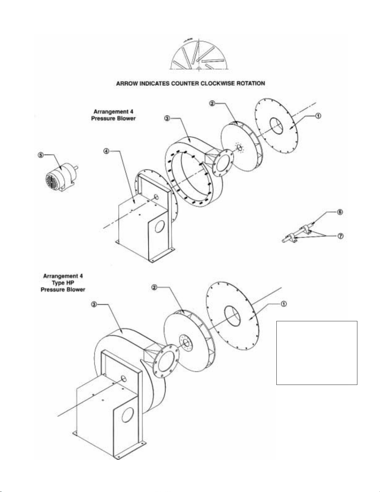
SPECIFY ROTATION AS VIEWED FROM DRIVE SIDE
Parts List
1. Inlet Plate Assembly
2. Wheel*
3. Housing*
4. Pedestal Assembly
5. Motor
6. Shaft
7. Bearings
* Order for parts must specify
rotation.
For assistance in selecting
replacement parts, contact
your local nyb representative
or visit: http://www.nyb.com.
Form 300 GPB 5M ABP
Printed in U.S.A.
 Loading...