

CAMCORP HVP with Duroflow Blower User Manual

MODEL HVP
(HIGH VOLUME PULSE)
DUST COLLECTOR BAGHOUSE
INSTRUCTION, OPERATIONS &
MAINTENANCE MANUAL
CAMCORP, INC.
Phone: 913-831-0740 Fax: 913-831-9271

TABLE OF CONTENTS
RECEIVING & INSPECTION OF UNIT ....................................................................... 1-1
SAFETY INFORMATION ............................................................................................. 2-1
OPERATING PRINCIPLE & SECTION/PARTS DETAIL........................................... 3-1
ON SITE STORAGE RECOMMENDATIONS ............................................................. 4-1
SETTING UP YOUR UNIT............................................................................................ 5-1
BAG & CAGE INSTALLATION ................................................................................... 6-1
START-UP CHECK LIST .............................................................................................. 7-1
START-UP DUST CONTROL SYSTEMS .................................................................... 8-1
SHUTDOWN PROCEDURES........................................................................................ 9-1
TROUBLE SHOOTING THE DUST COLLECTOR ................................................... 10-1
TOUBLESHOOTING THE CLEANING MECHANISM............................................ 11-1
SAFETY RECOMMENDATIONS............................................................................... 12-1
ROUTINE MAINTENANCE........................................................................................ 13-1
COMPONENT IOM MANUALS ................................................................................. 14-1
CAMCORP, INC.
Phone: 913-831-0740 Fax: 913-831-9271

RECEIVING YOUR UNIT
Prior to accepting shipment, care must be taken to inspect all equipment received both for
proper count and for damage. Any and all irregularities must be noted on the carriers’
copy of the shipping receipt to assist in settling any claims for damage or shortages. All
equipment is shipped FOB point of origin whether on a prepaid or collect freight basis.
ANY CLAIM FOR DAMAGE IN TRANSIT OR SHORTAGES MUST BE
BROUGHT AGAINST THE CARRIER BY THE PURCHASER.
Once your claim has been filed with the carrier contact CAMCORP to notify us of the
problem(s), and then we will advise the appropriate repair procedure or recommend it to
be returned to the factory depending on the extent of damage.
INSPECTION OF UNIT
Housing: Particular attention should be paid to the sheet metal housing of your collector.
The unit should be inspected for dents, cracks, or rips. A dented housing may seriously
affect the structural integrity of the unit. If any of these signs are present, note them on
the shipping receipt and notify CAMCORP immediately. The entire unit should be
checked against the certified drawings for correctness and the manufacturer notified
immediately if there are any discrepancies. No corrections may be made without the
expressed written consent of the manufacturer.
Components:
A count should be made of all pieces received and this should be verified
against the carrier’s manifest. Boxes should be inspected for rough handling, which may
have resulted in hidden damage.
1
-1
CAMCORP, INC.
Phone: 913-831-0740 Fax: 913-831-9271

*** SAFETY INFORMATION ***
WARNING!!! - Do not attempt to operate or maintain this piece of equipment until you
have read and understand all of the safety information included in the manual. This piece
of equipment contains moving which can cause serious injury. If you do not understand
anything in this manual seek assistance prior to operations.
LOCKOUT-TAGOUT REQUIREMENTS – Before installation, inspection, or
servicing this equipment perform an approved lockout-tagout procedure on the electrical
service, air supplies, or any other energy source. Refer to OSHA Standard 1910.147 for
guidelines.
SAFETY PRECAUTIONS – Do not operate, inspector, or service this equipment unless
all the following safety precautions are in effect:
• Guards, access doors, and covers are in place and secure.
• The equipment has been wired and grounded in accordance with all
applicable codes.
• An approved lockout-tagout procedure has been followed before the
equipment is inspected, disassembled, and/or serviced. The equipment is
automatically controlled and may start without warning unless energy
supplies are properly disconnected and locked out/tagged out.
• The control panel enclosure is closed and secured except as is necessary
for service or adjustment.
• The service door is closed and secured. Do not enter filter while the
system exhaust fan is operating. The airflow can pull service door closed
and trap personnel inside.
• A confined space permit, if required by authorities has jurisdiction, as
been obtained prior to personnel entering the unit. Check with your
company’s safety director for special instructions, testing prior to entry,
etc. that may be required by the specific application.
RESPONSIBILITY – It is the owner’s responsibility to maintain the safety features
included with this equipment. The safety features may include, but not necessarily be
limited to: guards, access doors and covers, explosions vents, warning decals, cautions
decals, and advisory decals. Replacement safety features are available from the
following:
CAMCORP Inc.
9732 Pflumm Road
Lenexa, KS 66214
Phone: 913-831-0740
Fax: 913-831-9271
Web site: www.camcorpinc.com
2-1
CAMCORP, INC.
Phone: 913-831-0740 Fax: 913-831-9271

OPERATION PRINCIPLE
A. Solids laden air or gases enter the unit at the hopper or housing inlet.
B. Air passes through the filter media.
C. Solids are retained on the filter media surface.
D. Cleaning consists of a rotating pulse arm with nozzles positioned over the bags
that randomly pulses 7-8” PSI air into the bags that reverses the airflow.
1. This momentarily takes a row of bags off stream through pressure reversal.
2. Flexing filter bags.
3. Solids are released to fall towards hopper and through rotary valve or other
discharge equipment.
3
-1
CAMCORP, INC.
Phone: 913-831-0740 Fax: 913-831-9271

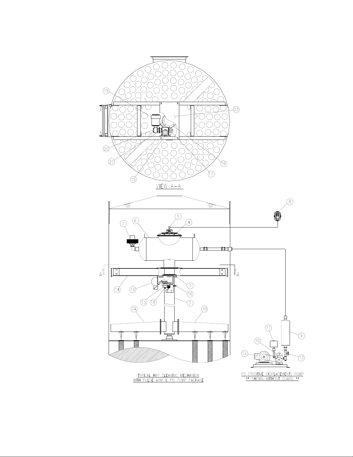
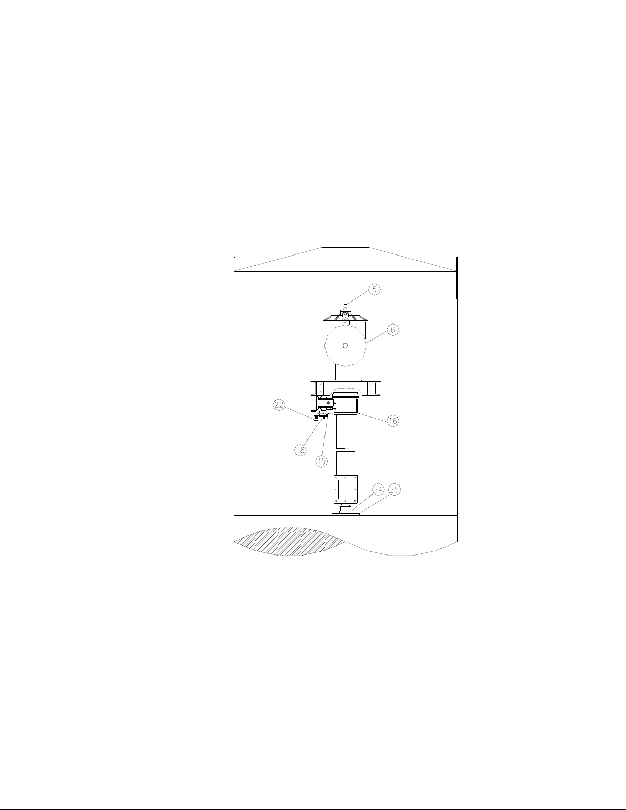
CAMCORP HVP (High Volume Pulse) Cleaning Mechanism Components
Item Quantity Description
1A 1 Pulse Arm (Size Determined by Model)
1B 1 Pulse Arm (Size Determined by Model)
2 1 8” OD Rotary Spool Section
3 1 8” OD Arm Rotation Support
4 1 8” Diaphragm Valve
5 1 Solenoid Valve – NEMA 4 or NEMA 9
6 1 Tank Assembly (Size Determined by Model)
7 1 2” Weighted Relief Valve
8 1 Solid State Timer
9 1 PD Pump Discharge Silencer (Size Determined by Model)
10 1 PD Pump (Size Determined by Model)
11 1 Inlet Filter (Size Determined by Model)
12 1 Motor, TEFC, 1800 RPM, 208-230/460/3/60 (Size Determined by Model)
13 1 0-15” PSI Pressure Gauge
14 2 Drive Mount Table Support Channel
15 1 50TTA2635 x 1” Sprocket & TTA35BS z 1” Torque Limiter Clutch
16 1 50A58 Drive Sprocket
17 1 Roller Chain Tensioner
18 1 206 Gearbox Drive Shaft
19 1 Motor, ½ HP, TEFC, 1800 RPM, 56C, 208-230-460/3/60
20 1 Primary Gear Reducer, 133Q56R20, 20:1 Ratio
21 1 Secondary Gear Reducer, 206Q56L40, 40:1 Ratio
22 1 Bracket Kit, 206S-BK (Secondary Reducer)
23 1 Drive Mount Support Table
24 1 4-Bolt Flange Thrust Bearing, 1 ½”
25 1 Bearing Mounting Plate
3-2
CAMCORP, INC.
Phone: 913-831-0740 Fax: 913-831-9271
3-3
CAMCORP, INC.
Phone: 913-831-0740 Fax: 913-831-9271
3-4
CAMCORP, INC.
Phone: 913-831-0740 Fax: 913-831-9271

ON SITE STORAGE RECOMMENDATIONS
I. Baghouse and Housing
1. Housing can be stored outside.
2. Equipment must be blocked up to keep the flanges out of the dirt.
3. Many units are supplied with a plain finish bare steel interior. If storage of
more than two week is anticipated, the interior should be prime coated before
storage.
4. Covering the unit with a tarp is recommended to keep the interior from rusting
or corroding as well as keeping the finish in new condition. However, the tarp
is not absolutely necessary.
II. Bags & Cages
1. Bags must be stored inside a cool dry area protected from rodents and insects.
2. For extended storage the boxes for the bags should be wrapped with plastic
wrap or stretch wrap to protect from moisture.
3. If the bags get wet for any reason, immediately lay them out with adequate
ventilation to dry in order to prevent mold and mildew.
4. It is recommended to store the cages inside a dry area if at all possible.
5. If an inside location is not available, cages can be stored outside as long as they
are covered by a tarp.
6. Cages are generally stored horizontally on pallets to keep off the ground.
7. If cages can be stored horizontally, do not stack over three boxes high.
8. If the job site is in an area that may receive a significant snow load, the cages
must be stored vertically in order to prevent being crushed by the weight of the
snow. Do not stack more than one box high.
III. Accessory Parts
. This includes all gauges, bag clamps, nylon or copper tubing, gaskets, and other
1
ports not specifically called out.
2. These items should be stored inside a cool dry place protected from insects and
rodents.
4
-1
CAMCORP, INC.
Phone: 913-831-0740 Fax: 913-831-9271

ON SITE STORAGE RECOMMENDATIONS (continued)
IV. Fan and Fan Accessories
1. Fans can be stored outside on a pallet or skid to keep out of water and dirt.
2. Equipment should be covered with a tarp to protect from the bags.
3. Fan silencers, outlet dampers, and inlet boxes should also be tarped and stored
on a pallet or skid.
V. Ducting
1. Ducting can be stored outside on a pallet or skid to keep it off the ground. It
should be positioned so that water does not sit in the equipment.
2. If ducting is unpainted steel, it should be at least primed coated before storage.
3. If ducting is already finish coated, it should be tarped to protect the finish but is
not absolutely necessary.
VI. Knife Gate
1. All limit switches, solenoids, and air cylinder ports must be capped and taped to
prevent any moisture or dirt from entering.
2. Equipment can sit outside provided it is covered with a tarp and is on a pallet or
skid to keep it out of the water and dirt.
VII. Isolation Dampers
1. All limit switches, solenoids, and air cylinder ports must be capped and taped to
prevent any moisture or dirt from entering.
2. Equipment can sit outside provided it is covered with a tarp and is on a pallet or
skid to keep it out of the water and dirt.
VIII. Rotary Valve
1. Rotor and interior of valve should be well oiled with vegetable
oil to prevent
rust and to maintain compatibility with product.
2. Unit can be stored outside provided it is covered with a tarp and is on a pallet or
skid to keep it out of the water and dirt.
4-2
CAMCORP, INC.
Phone: 913-831-0740 Fax: 913-831-9271

ON SITE STORAGE RECOMMENDATIONS (continued)
IX. Butterfly (Wafer Valve)
1. All limit switches, solenoids, and air cylinder ports must be capped and taped to
prevent any moisture or dirt from entering.
2. Unit can be stored outside provided it is covered with a tarp and is on a pallet or
skid to keep it out of the water and dirt and sunlight.
X. Level Indicators
Store these items inside a cool dry area protected f
rom rodents
XI. AC Inverters
Store these items and all other electrical controls inside a cool dry area protected
from rodents.
4-3
CAMCORP, INC.
Phone: 913-831-0740 Fax: 913-831-9271

SETTING UP YOUR UNIT
CAMCORP dust collectors are shipped in various states of assembly depending on the
size and configuration of the unit. Before attempting to move the dust collector or any of
its sections, review both the certified general assembly drawing supplied with your unit
and the rigging and lifting guidelines included in this manual. Become familiar with the
size and number of sections to be assembled, the orientation of inlet(s), outlet(s), access
door(s), and fan as well as the number and location of lifting lugs.
Dust collectors of this type are manufactured from steel sheets and are quite flexible.
Therefore, even though care has been taken to maintain dimensional accuracy and
squareness, some difficulty should be anticipated, and temporary bracing in the field may
be required.
Rigging and Lifting Guidelines
1. Do not lift the dust collector by any attachments other than the lifting lugs
provided.
2. Use all of the lifting lugs provided on the dust collector, or a section of the
dust collector, when making a lift.
3. If the lifting lugs are located below the roof line of the dust collector or
below the top of the section of the dust collector, a vertical pull must be made
to avoid crushing the top of the unit. Use spreader beams to accomplish this
vertical pull.
4. Attach tag lines at several locations to be able to control the unit when lifted
and to prevent spinning or swinging.
5. The dust collector should be lifted and lowered at a slow, uniform rate and
not allowed to bounce or joggle since this can cause excessive impact
stresses at the lift points.
Doors and Flanges
: Hold-downs on doors should only be hand tightened. Excessive
pressure can distort the door panel itself resulting in leakage. All bolts on flanges should
be tight. All holes in the dust collector must be plugged prior to start-up if not being
connected.
5-1
CAMCORP, INC.
Phone: 913-831-0740 Fax: 913-831-9271

Platform Installation: The platform, ladder, handrail, and bracing are to be installed as
shown on the special platform detail provided. Use the part ID’s to locate the parts in the
proper location.
Explosion Vents (where applicable):
1. Figure 6 – The explosion vents are attached with
a minimum of standard
steel fasteners for shipment. THESE MUST BE REMOVED and the
PVC Bolts installed that are included in the shipment. Extreme care should
be exercised when installing the PVC Bolts as they are very fragile. A
gasket is factory installed that will provide a seal between the vent panel
and the frame. DO NOT use silicone sealer or any other sealer or adhesive
at this joint as this will prevent the vent from operating properly.
2. The area around the vents should be clear of any personnel or obstructions
to prevent injury or damage.
5
-2
CAMCORP, INC.
Phone: 913-831-0740 Fax: 913-831-9271
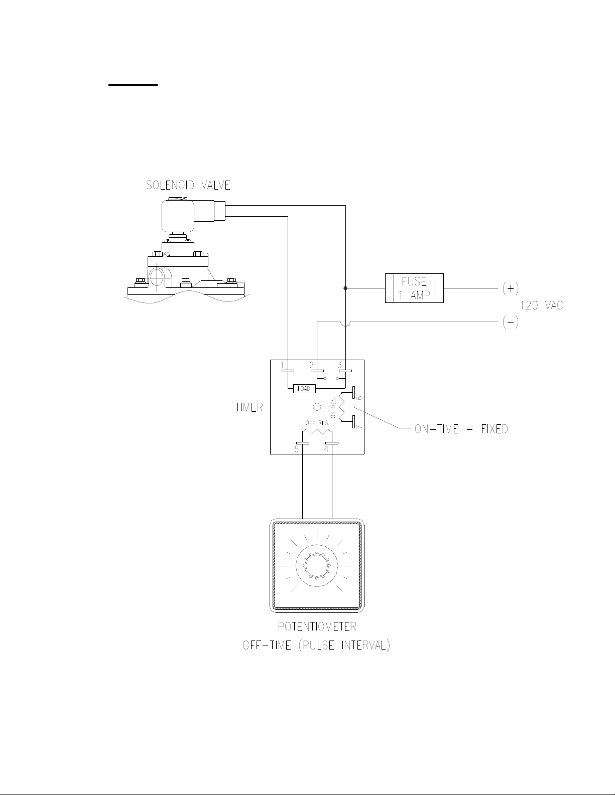
Electrical: A 120-volt, 60-Hertz, 1-Amp circuit is required to operate the dust
collector’s Solid State Timer. A 230/460V 3-phase circuit is required to run the Pulse
Arm drive motor and the Cleaning Air PD (Positive Displacement) pump motor. Note:
The Adjustable Timer needs to be mounting were the Pressure Gauge on the PD Pump is
visible.
5-
3
CAMCORP, INC.
Phone: 913-831-0740 Fax: 913-831-9271

Gauges: Check the pressure differential gauge to make sure that the high-pressure tap is
connected below the tube sheet and the low-pressure tap is connected above the tube
sheet. Verify that the gauge have been zeroed prior to connection when it is in its
permanent mounting position.
Cleaning Air PD Pump: The PD Pump must be install at the base of the filter to
accommodate installation of the Air Supply line. Securely anchor in permanent location.
Required line size as follows:
Air Supply
Model: Pipe Diameter
HVP48 thru 112 1”
HVP 152 thru 256 1-1/2”
HVP 312 thru 504 2”
Auxiliary Equipment: All auxiliary equipment must be installed according to its
manufacturer’s specifications and interlocked with the entire system as needed. Direction
of rotation of each item must be checked prior to start-up of the entire system.
5-4
CAMCORP, INC.
Phone: 913-831-0740 Fax: 913-831-9271

TOP LOAD BAG AND CAGE INSTALLATION
1. Inspect the cage for any signs of damage, warping, bent wires, or missing
welds.
2. Inspect the filter bag for any signs of mold, mildew, ripped seams, or holes.
3. Lower the closed end of the bag through the hole in the tube sheet.
4. With your hands, “kidney shape” the snap band bag top in order to fit and
align it within the tube sheet hole.
5. Fit the groove of the snap band to the I.D. of the tube sheet hole and allow it
to expand and audibly snap into place. If the band will not snap into place
initially, do not push on the “dimple” as doing this will permanently damage
the snap band. Instead, kidney shape the snap band from the opposite side of
the band. Then you can allow the band to expand and audibly snap into
place.
6. Check the fit of the snap band to the tube sheet. It should be even in height
above the tube sheet around the entire circumference, which will confirm to
the installer that the tube sheet is centered and well secured into the middle
groove of the snap band.
7. Lower the cage into the bag and press that cage top down into the bag’s snap
band I.D. When in position, the rolled flange of the cage top will rest on the
tube sheet and the bag and cage assembly will be rigidly mated. The O.D. of
the cage top provides a compression fit to the I.D. of the snap band.
8. Disconnect the drive chain to allow the pulse arm to rotate freely to access
the holes under the arm if necessary.
9. Replace access doors and tighten accordingly. You are ready to begin startup procedures if all other preceding tasks and hook-ups are completed.
6
-1
CAMCORP, INC.
Phone: 913-831-0740 Fax: 913-831-9271

START-UP CHECKLIST
1. Installation
Make sure the unit is secured to grade. The ladder(s) and platform(s) must be
tightened and set up according to OSHA requirements. Ducting and piping must
be secured and routed out of the way of traffic whenever possible to avoid injury.
Ducting must also be free of all debris including moisture.
2. Interior of the dirty air plenum
A. Make sure that the filter bag assemblies hang straight and the bottoms do not
touch each other or any part of the collector interior. If this occurs, the bags
will have holes worn in them wherever they contact and will require
replacement.
B. High-level alarms should be connected sufficiently below the air inlet(s) to
avoid a plugged up inlet or blinded off filter bags.
3. Clean air plenum
A. Properly install weights onto Weight Relief valve the end of the tank
assembly.
B. All bolts on the flanges must be in place and properly tighten.
C. Verify that the pulse arm drive is properly installed.
D. Note: Gear Reducers are shipped without oil. Reference attached Manual for
proper level.
4. Positive Displacement Pump
A. All supply air lines must be clean internally before connecting to blower.
B. Verify Inlet filter is properly installed.
C. Verify V-belt alignment and tension.
D. Note: PD pump is shipped without oil. Reference attached Manual for
proper level.
E. Verify proper rotation.
7-1
CAMCORP, INC.
Phone: 913-831-0740 Fax: 913-831-9271

5. Exterior of dust collector
A. Access doors, inspection ports, and relief vents should seat effectively to
prevent leakage.
B. All bolts must be properly tightened.
C. Operate any equipment connected to the dust discharge of the dust collector.
Check the rotation of any motor driven equipment such as rotary airlocks,
horizontal unloading valves, live bottom bin activators, and screw conveyors.
Check slide gates and butterfly valves for binding.
6. Explosion relief panels – shear bolt style (where applicable)
A. Inspect for broken or missing bolts.
7-2
CAMCORP, INC.
Phone: 913-831-0740 Fax: 913-831-9271

START-UP DUST CONTROL SYSTEMS
1. Fan or blower system
A. Start the fan or blower and check rotation.
B. Check dust pickup points for proper suction; balance airflow in individual
ducts.
C. Check for air leakage at all flanged connections.
2. Equipment start-up sequence
A. Start the pulse arm drive motor (direction of rotation is not critical).
B. Start the PD pump motor and check rotation.
C. Adjust timer Off-time by watching pressure gauge on PD pump. The
pressure in the tank should peak between 7-8 PSI. Increase or Decrease time
to obtain the correct pressure. Note: Verify the Weighted relief valve in the
clean air plenum is not activating – decrease Off-time if it is bleeding air.
D. Dust take away equipment such as rotary airlocks, screw conveyors,
horizontal unloading valves, live bottom bin activators, and pneumatic
conveying systems can now be started in their correct sequence.
E. Check that all access doors, hatches, ports, and other openings are closed and
latched or bolted.
F. The main exhaust fan can now be started and brought up to speed.
G. Start the dust laden air through the collector. The collector should be started
under partial load to allow the bags to become slowly and evenly coated with
dust particles.
On pneumatic conveying systems, watch the differential pressure gauge
closely for the first hour or so. If unstable, the collector discharge system
may be too small for the volume it is seeing. A quick fix is to reduce the
material feed until the discharge rate can be increased.
8-1
CAMCORP, INC.
Phone: 913-831-0740 Fax: 913-831-9271

H. Observe the manometer or magnahelic differential pressure gauge reading.
As the new filter bags become coated with dust, the efficiency of the filtering
action increases, and the differential pressure across the filter bags will also
increase. Slowly bring the collector to full load and note the final pressure
drop across the filter bags. Never allow the pressure drop across the filter
bags to exceed 17” w.g. maximum or filter bags may collapse.
I. Check the main airflow with a Pitot tube, or equivalent measuring device, to
establish initial conditions. If the main airflow must be adjusted up or down
to suit the process, repeat step 2-H above.
8-2
CAMCORP, INC.
Phone: 913-831-0740 Fax: 913-831-9271

SHUT-DOWN PROCEDURES
1. Dust control systems
Reverse start-up procedure, shut down fan, then after 5 or 10 minute delay, shut
down the PD pump and pulse arm drive motor.
2. Pneumatic systems
Reverse start-up procedure, shut down fan, then after 5 or 10 minute delay, shut
down the reverse air fan and sweep arm drive motor.
9
-1
CAMCORP, INC.
Phone: 913-831-0740 Fax: 913-831-9271

TROUBLESHOOTING THE DUST COLLECTOR
I. Excessive pressure drop across filter bags
The differential pressure gauge or manometer on your dust collector should read
6” w.g. or less. Higher readings and/or steadily increasing readings are an
indication that the main airflow through the dust collector may be restricted, and
a potential process problem such as poor suction at duct pickup points may
exist. In extreme cases (over 17” w.g.) filter bags will be damaged. Check the
following:
A. Pressure Gauge
Check the differential pressure gauge or manometer and the tubing leading
to the dust collector for proper operation. Disconnect the lines at the gauge
or manometer and clear with compressed air. Look for loose fittings,
cracked, broken, or pinched tubing. Make sure the gauge is zeroed or that
the manometer is level, zeroed and contains the correct fluid.
B. Bags Loaded with Dust
If the cleaning system is not operating properly refer to the section titled
“Troubleshooting the Cleaning System”.
A condition known as blinding. If the dust is dry, see paragraph
1-4; if the dust is wet, see paragraphs 5 and 6.
1. Dust Not Discharging from the Hopper
Check hopper for over-loading or bridging across the dust discharge.
Correct by repairing dust discharge equipment, replacing with higher
capacity equipment, or installing hopper vibrators, etc. as required to
keep the hopper clear.
2. Air Flow too High
If the main airflow is too high to allow dust to drop off of the filter bags,
an excessive pressure drop across the dust collector will result and dust
will build up in the system. In many cases this high pressure drop in
turn leads to a reduction in the main air flow so that it is necessary to
remove the dust accumulation from the filter bags (and the rest of the
system) before measuring the main air flow volume.
10-1
CAMCORP, INC.
Phone: 913-831-0740 Fax: 913-831-9271

TROUBLESHOOTING THE DUST COLLECTOR (continued)
Visually inspect the bags for heavy caking; if caking is evident, see the
note below and take the necessary action to clean the bags. Next,
measure the main airflow with a pitot tube or equivalent devise and
compare with the original volume for which the unit was designed. If
the flow is too high, cut back the main fan to prevent a recurrence of the
problem.
3. Particle Size and Dust Load
If possible, compare the dust particle size and loading with the original
design specifications. Finer dust may cause a higher pressure drop. Do
not hesitate to call the factory; we have experience with many kinds of
dust.
4. Bags Too Tight
ags that have shrunk on their cages may not flex sufficiently during the
B
compressed air pulse to loosen caked dust. If the bags were cleaned or
laundered, pull a bag tight around its cage; you should be able to
“gather” a small fold of material between your fingers.
5. Water Leaks
Inspect the dust collector housing and ductwork for holes, cracks, or
loose gasketing where water could enter the collector.
6. Condensation
If moisture has been condensing inside the collector, check the dew
point temperature of the incoming air stream. If may be necessary to
insulate the collector and/or the ductwork leading to the collector to keep
surface temperatures above the dew point and prevent condensation of
the filter bags.
NOTE: Collectors that have had blinded or caked bags can possible be
put into service by running the pulsing air system for 15 to 30 minutes
without the main fan or blower. If the pressure drop is not lower when
the main fan is started again, take the bags out of the collector and
remove the caked dust by special dry-cleaning. Information pertaining
to filter bag cleaning may be obtained by calling your CAMCORP sales
representative.
10-2
CAMCORP, INC.
Phone: 913-831-0740 Fax: 913-831-9271

TROUBLESHOOTING THE DUST COLLECTOR (continued)
II. Extremely Low Pressure Drop
A. Pressure Gauge
Check the differential pressure gauge or manometer and the tubing leading
to the dust collector as in I-A of this section.
B. Holes in Filter Bags or Bags Incorrectly Installe
d.
Inspect the filter bags for holes, rips, tears, or excessive wear. Make sure
that the filter bags were installed correctly according to the “Bag & Cage
Installation” section.
C. Ductwork and Dampers
Inspect the ductwork to and from the dust collector for air leaks or blockage.
Make sure that any dampers in the system are correctly positioned to allow
air to flow through the dust collector.
D. Leaks in the Housing
Check the tube sheets (flat steel sheets from which the filter bags are
suspended) and the dust collector housing for holes, cracks or loose
gasketing that would permit air to bypass the dust collector or filter bags.
III. Continuous Flow of Dust in the Clean Air Exhaust (Primary Dusting)
A. Holes in the Filter Bags or Bags Incorrectly Installed
Inspect the filter bags as in II-B this section.
B. Holes in the Tube Sheets
Check the tube sheets for holes, cracks, or loose bolts that would permit
dusty air to bypass the filter bags.
IV. Puff of dust in the clean air exhaust after each pulse (secondary dusting)
A. Worn filter bags
nspect the filter bags for wear. Thin bags may not stop fine dust when
I
flexed by a compressed air pulse.
10-3
CAMCORP, INC.
Phone: 913-831-0740 Fax: 913-831-9271

TROUBLESHOOTING THE DUST COLLECTOR (continued)
B. Residual Dust
If dust has gotten into the clean air plenum because of a dropped or torn bag,
hole in tube sheet, etc., the pulse air may stir up the dust and allow it to
escape into the clean air exhaust. Residual dust may also be driven down
inside the filter bags by the pulse air; if the filter bags are filled with several
inches of dust, clean both the clean air plenum and the filter bags to avoid
further problems.
V. Short Filter Bag Life
This is often a complicated problem to diagnose and we recommend calling the
factory for advice. The following list may be helpful in performing some
preliminary check:
A. Temperature
Operating Temperature above the recommended limit of the filter bag
material.
B. Chemical Attack
Bag material degrades due to attack from certain chemicals in the dust or
gasses in the air stream.
C. High Moisture
High moisture content in the collector may cause certain filter bag material
to shrink or degrade (more rapidly at elevated temperatures).
D. Localized abrasion
Abrasion of the bags at the dusty air inlet; a dust impingement baffle may be
required.
E. Internal Bag Supports Gone Bad
Corroded, rusted or broken filter cages can cause excessive bag wear.
Stainless steel or coated cages are available.
10-4
CAMCORP, INC.
Phone: 913-831-0740 Fax: 913-831-9271
 Loading...