

CAMCORP Cartridge Collector User Manual

Installation, Operation,
& Maintenance Manual
CAMCORP
Pulse-Jet
Filter Cartridge
Top & Bottom Load
Dust Collector
Unique Design & Engineering
Approaches for Industrial
Applications

TABLE OF CONTENTS
Section 1 - SAFETY
Safety Recommendations ............................................................................ 1-1
Section 2 - RECEIVING
Receiving & Inspection of the Unit............................................................. 2-1
Storage Recommendations .......................................................................... 2-2
Section 3 - INSTALLATION
Setting Up Your Unit...................................................................................3-1
Pleated Filter Cartridge Installation............................................................. 3-5
Electrical Wiring Diagram......................................................................... 3-11
Magnehelic Gauge Connections................................................................ 3-12
Explosion Vent Installation....................................................................... 3-13
Section 4 - OPERATION
Operating Principle...................................................................................... 4-1
Start-Up Check List.....................................................................................4-2
Start-Up Dust Control Systems ................................................................... 4-5
Shutdown Procedures .................................................................................. 4-6
Section 5 – COMPONENT INFORMATION
Main Component Listing............................................................................. 5-1
Magnehelic Gauge....................................................................................... 5-3
Timer............................................................................................................ 5-7
National Controls Corp – 120 VAC Standard Timer ............................ 5-7
National Controls Corp – 12-24 VDC (Optional) ................................. 5-9
Dwyer Smart Timer (Optional) ........................................................... 5-11
Diaphragm Valves..................................................................................... 5-19
Goyen #RCA20DD – ¾” Valve........................................................... 5-19
Goyen #RCA25DD – 1” Valve............................................................ 5-20
Goyen #RCA45DD – 1 ½” Valve........................................................5-21
CAMCORP, INC.
Phone: 913-831-0740 Fax: 913-831-9271
www.camcorpinc.com

Section 6 - TROUBLESHOOTING
Dust Collector.............................................................................................. 6-1
Timer............................................................................................................ 6-5
Compressed Air System .............................................................................. 6-6
Section 7 - MAINTENANCE
Routine Maintenance................................................................................... 7-1
Section 8 – APPENDIX
Dust Collector Terms & Definitions ........................................................... 8-1
CAMCORP, INC.
Phone: 913-831-0740 Fax: 913-831-9271
www.camcorpinc.com

Section 1 – Safety Recommendations
Because this unit may be under pressure or vacuum do not attempt to open any
device, doors or panels while fans or blowers are running. The unit has air hoses
and valves with a maximum recommended operating pressure of 100 psig. To
eliminate the danger of bursting care must be taken to insure maximum desired
pressure is not exceeded.
Before servicing any portion of the compressed air system the air supply must be
shut off and any pressure relieved.
If your unit is equipped with a discharge auger or an airlock assure that chain
guards are installed before start-up and servicing is attempted only after
electrical power is locked out.
While servicing the filter it is very important that there are no open flames,
welding or grinding sparks. Dust laden air could be highly explosive and extreme
care must be taken. Most filter cartridges will burn if exposed to sparks, welding
or open flames.
Before entering any dust collector:
• Run cleaning mechanism 20 minutes with the fan off to clean the filter
cartridges.
• Completely discharge dust solids from hopper, if applicable.
• Shut off compressed air supply and relieve pressure in the compressed air
manifold.
• Lock out all electrical power on all equipment especially rotating
equipment.
• On toxic operation, purge collector housing and install a blank in the inlet
duct.
• Install catwalks and safety cables as required.
• Secure access doors in an open position or remove doors.
• Use the buddy system.
• Wear a respirator or appropriate breathing equipment.
• Use common sense.
Follow all current OSHA regulations relative to Lockout / Tag-Out and Confined
Space Entry and any other applicable regulations when servicing your
equipment.
On the following page are examples of safety stickers you will find on Camcorp
equipment. These will help identify potential hazards on the equipment.
1-1
CAMCORP, INC.
Phone: 913-831-0740 Fax: 913-831-9271
www.camcorpinc.com

Examples of Safety Stickers
------DANGER------
-----CAUTION------
-------OTHER-------
These stickers provide
instruction or helpful
information.
The DANGER &
CAUTION stickers
indicate serious potential
hazards which may result
in serious injury or
possible death. Extreme
care should be observed
when working in these
areas.
1-2
CAMCORP, INC.
Phone: 913-831-0740 Fax: 913-831-9271
www.camcorpinc.com
Serial Number Plate
Important information
contained on these is
needed by Camcorp when
calling for parts or service.

Section 2 - Receiving
Receiving the Equipment
Prior to accepting the shipment(s) care must be taken to inspect all
equipment received both for proper count and for damage. Any and all
irregularities must be noted on the carrier’s copy of the shipping receipt to
assist in settling any claims for damage or shortages. All equipment is
shipped FOB point of origin whether on a prepaid or collect freight basis.
ANY CLAIM FOR DAMAGE IN TRANSIT OR SHORTAGES
MUST BE BROUGHT AGAINST THE CARRIER BY THE
PURCHASER.
Once your claim has been filed with the carrier, contact CAMCORP to
notify us of the problem(s). We will then advise the appropriate repair
procedure or recommend it be returned to our factory, depending on the
extent of the damage.
Inspection of the Equipment
Housing, Compressed Air Header and Timer Assembly: Particular
attention should be paid to the sheet metal housing of your collector. The
unit should be inspected for dents, cracks or rips. A dented housing may
seriously affect the structural integrity of the unit. The compressed air
header and timer assembly are very delicate pieces of the unit and must
be checked carefully for any signs of impact, warpage or loose fittings. If
any of these signs are present note them on the shipping receipt and
notify CAMCORP immediately. The entire unit should be checked against
the certified drawings for correctness. CAMCORP should be notified
immediately if there are any discrepancies. No corrections may be made
without the expressed written consent of CAMCORP.
Components: A count should be made of all pieces received and this
should be verified against the carrier’s manifest. Boxes should be
inspected for rough handling, which may have resulted in hidden damage.
2-1
CAMCORP, INC.
Phone: 913-831-0740 Fax: 913-831-9271
www.camcorpinc.com

Storage Recommendations
Baghouse, Bin Vent, Filter Receiver, Dirty Air Hopper and Housing
• Housing can be stored outside.
• Equipment must be blocked up to keep the flanges out of the dirt.
• Most units are supplied with a plain unfinished interior. If storage of more
than two weeks is anticipated the interior should be prime coated before
storage.
• Covering the unit with a tarp is recommended to help keep the interior
from rusting or corroding as well as keeping the outer finish in new
condition, however a tarp is not absolutely necessary.
Baghouse, Bin Vent, Filter Receiver, and Clean Air Plenum
• Unit can be stored outside.
• Compressed air header, diaphragm and solenoid valves must be tarped
for weather protection.
• Position unit so water will not get in or remain inside the tube sheet area.
• Unit must be blocked up to keep the flanges, bag cups, venturis and air
header out of water and dirt.
• Ports on diaphragm and solenoid valves must be plugged and taped to
keep insects, dirt and moisture out.
• For extended storage (more than 4 weeks), it is recommended to remove
the timer panel and solenoid valve assembly (if mounted). These
components should be stored inside a cool dry area along with the copper
or black nylon tubing. The solenoids should have all ports capped and
taped to protect from insects, dirt and moisture.
• The unit should be tarped but is not absolutely necessary.
Pleated Filter Cartridges
• Filter cartridges must be stored inside a cool dry area protected from
moisture, rodents and insects.
• For extended storage the boxes for the filter cartridges should be wrapped
with plastic wrap or stretch wrap to protect from moisture.
• If the filter cartridges get wet for any reason, immediately lay them out with
plenty of ventilation to dry in order to prevent mold and mildew.
2-2
CAMCORP, INC.
Phone: 913-831-0740 Fax: 913-831-9271
www.camcorpinc.com

Storage Recommendations (continued)
Accessory Parts
• This includes all gauges, cartridge clamps, nylon or copper tubing, valves,
gaskets and other parts not specifically called out.
• These items should be stored inside a cool dry place protected from
moisture, insects, and rodents.
Fan and Fan Accessories
• Fans can be stored outside on a pallet or skid to keep them out of water
and dirt.
• Fan silencers, outlet dampers, and inlet boxes should also be tarped and
stored on a pallet or skid.
• Reference fan IOM manual for long-term storage.
Ducting
• Ducting can be stored outside on a pallet or skid to keep it off the ground.
It should be positioned so that water does not sit on or in the ducting.
• If ducting is unpainted carbon steel it should be at least primed coated
before storage.
• If ducting is already finish coated, it should be tarped to protect the finish,
but this is not absolutely necessary.
Knife Gate
• All limit switches, solenoids, and air cylinder ports must be capped and
taped to prevent any moisture or dirt from entering.
• Equipment can sit outside provided it is covered with a tarp and is on a
pallet or skid to keep it out of water and dirt.
• Reference knife gate IOM manual for long-term storage.
2-3
CAMCORP, INC.
Phone: 913-831-0740 Fax: 913-831-9271
www.camcorpinc.com

Storage Recommendations (continued)
Isolation Dampers
• All limit switches, solenoids, and air cylinder ports must be capped and
taped to prevent any moisture or dirt from entering.
• Equipment can sit outside provided it is covered with a tarp and is on a
pallet or skid to keep it out of water and dirt.
Rotary Valve
• Rotor and interior of valve should be well oiled with vegetable oil to
prevent rust and to maintain compatibility with product.
• Unit can be stored outside provided it is covered with a tarp and is on a
pallet or skid to keep it out of water and dirt.
• Reference rotary valve IOM manual for long-term storage.
Butterfly (Wafer Valve)
• All limit switches, solenoids, and air cylinder ports must be capped and
taped to prevent any moisture or dirt from entering.
• Unit can be stored outside provided it is covered with a tarp and is on a
pallet or skid to keep it out of water, dirt and sunlight.
• Reference butterfly valve IOM manual for long-term storage.
Level Indicators
• Store these items inside a protected cool dry area.
AC Inverters
• Store these items and all other electrical controls inside a protected cool
dry area.
2-4
CAMCORP, INC.
Phone: 913-831-0740 Fax: 913-831-9271
www.camcorpinc.com

Section 3 - Installation
Setting Up Your Unit
CAMCORP dust collectors are shipped either in one piece, fully assembled,
or in two or more sections depending on the unit size and weight. Before
attempting to move the dust collector or any of its sections review both the
certified general assembly drawing supplied from CAMCORP and the
rigging and lifting guidelines included in this manual. Become familiar with
the size and number of sections to be assembled, the orientation of inlet(s),
outlet(s), access door(s) and compressed air header(s), as well as the
number and location of lifting lugs.
Dust collectors of this type are manufactured from steel sheets or plate and
are quite flexible. Therefore, even though care has been taken to maintain
dimensional accuracy and squareness, some difficulty should be anticipated
and temporary bracing in the field may be required.
The following sequential procedure will help to minimize any assembly
difficulties:
STEP 1: Set up the supporting steel for the dust collector level and square.
Precision at this point will greatly help facilitate erection and bolt hole
alignment of the dust collector sections to follow.
STEP 2: Place the hopper with its girth channel on the supporting steel
work. Check for squareness, and for bolthole alignment between the hopper
flange and the girth channel. Apply the appropriate RTV silicone caulk
around the periphery of the hopper flange with one bead on each side of the
boltholes.
STEP 3: Lift the dirty air plenum, with the tube sheet, into place. DO NOT
LOWER THE PLENUM ONTO THE HOPPER FLANGE UNTIL
ALIGNMENT IS ACCOMPLISHED. The silicone caulk makes horizontal
movement very difficult once a load is applied. With the plenum suspended
over the hopper ½” to 1”, begin bolt hole alignment starting at the center of
the plenum and working toward the ends by using tapered drift pins. If the
wall(s) has flexed out of square it will be necessary to pry or pull it back into
alignment. Depending on the size of the unit and the degree of difficulty
hydraulic jacks and come-alongs may be required. When the mating holes
are properly aligned, finish lowering the plenum. Install the remaining bolts,
washers, and nuts and torque to the appropriate specifications.
3-1
CAMCORP, INC.
Phone: 913-831-0740 Fax: 913-831-9271
www.camcorpinc.com

Setting Up Your Unit (continued)
Step 4: Check the top of the dirty air plenum for squareness and bolthole
alignment between the dirty air plenum and the tube sheet. Make sure that
the silicone caulk has been applied between the top flange of the dirty air
plenum and the underside of the tube sheet flange. Next, apply the caulk
around the periphery of the topside of the tube sheet flange one bead to
each side of the boltholes.
STEP 5: Lift the clean air plenum into place and assemble in the same
fashion as in STEP 3. Again, do not lower the clean air plenum completely
until preliminary alignment is accomplished. Start drift pin alignment at the
center of the plenum on the compressed air header side since the header
makes access to the flange more limited. When alignment is complete install
the remaining bolts, washers, and nuts and torque to the appropriate
specifications.
All CAMCORP dust collectors are provided with lifting lugs for ease in
handling of the units during field erection and installation. The number and
location of these lifting lugs will vary depending on the model, size, and
weight of the dust collector. Before attempting to rig and lift your dust
collector review the certified general assembly drawing supplied from
CAMCORP to verify the number and location of lifting lugs as well as visually
checking this information on the actual unit. Large units are frequently
shipped in several sections so check the lifting lugs provided on each
section. If these cannot be used or there is some question about lifting lug
location consult the engineering staff at CAMCORP for proper location since
proper care must be taken to prevent damage to housing or its components.
Rigging and Lifting Guidelines
Do not lift the dust collector by any attachments other than the lifting lugs
provided.
Use all of the lifting lugs provided on the dust collector or a section of the
dust collector when making a lift.
If the lifting lugs are located below the roofline of the dust collector or
below the top of the section of the dust collector a vertical pull must be
made to avoid crushing the top of the unit. Use spreader beams to
accomplish this vertical pull.
3-2
CAMCORP, INC.
Phone: 913-831-0740 Fax: 913-831-9271
www.camcorpinc.com

Setting Up Your Unit (continued)
Attach tag lines at several locations to help in controlling the unit when
lifted and to prevent spinning or swinging.
The dust collector should be lifted and lowered at a slow, uniform rate
and not allowed to bounce or joggle since this can cause excessive
impact stresses at the lift points.
Compressed Air Manifold: Typically, CAMCORP ships the compressed
air manifold installed complete with diaphragm valves and solenoid
enclosure(s), except when units are over legal shipping width with them
in place.
Doors and Flanges: Hold-downs on doors should only be hand
tightened. Excessive pressure can distort the door panel itself resulting
in leakage. All bolts on flanges should be tight. All ports in the dust
collector not being used must be plugged prior to start-up.
Electrical: A 120 volt 60 Hertz circuit is required to operate the dust
collector’s pulse-jet cleaning system (unless a different voltage for
components was requested). This timer must be wired according to the
wiring diagrams and be provided with a circuit that is free from transient
currents. The timer has a feature called “Demand Pulse” that allows the
output terminals to be energized and de-energized by the high and low
set points of a differential pressure switch such as a Dwyer Photohelic
Series 3000. The “Demand Pulse” terminals are marked “Pressure
Switch”. Do not over fuse.
The NCC pulse timer boards have adjustable pulse duration and interval
(time between valves firing) settings. Before applying power to the timer
always check these settings according to the table below. Since there are
many variances in operations and conditions these are presented only as
initial start-up guidelines. If you experience problems in cleaning of the
filter bags, please contact CAMCORP.
TIMER BOARD ADJUSTMENTS
(Recommended at start-up)
VALVE SIZE PULSE DURATION INTERVAL
¾” .10 to .12 seconds 20 to 25 seconds
1” .10 to .12 seconds 20 to 25 seconds
1-½” .06 to .08 seconds 20 to 25 seconds
3-3
CAMCORP, INC.
Phone: 913-831-0740 Fax: 913-831-9271
www.camcorpinc.com

Setting Up Your Unit (continued)
The firing sequence of the diaphragm valves on the dust collector should
be set so that no two adjacent rows of cartridges fire in succession to
insure maximum cleaning and life of the filter media. This can only be
achieved when wiring the pulse timer board to the solenoid valves. If you
are experiencing a high-pressure drop across the filter bags in your dust
collector the pulse interval should be reduced.
Apply electrical power to the timer and make sure that it is cycling
completely through all rows of the unit. In some cases the timer panel
may have more “positions” than required in which case the position
selector cable needs to be attached to the proper numerical value
corresponding to the number of diaphragm valves on the unit.
If your dust collector was shipped via common carrier rather than a
contract hauler there is a possibility that the solenoid enclosure was not
shipped installed on the unit. If this is the case, there is a mounting plate
welded on the housing or the air header with the bolt pattern of the
enclosure already drilled. Bolt the enclosure and install the nylon (or
copper) tubing with the fittings provided making sure that the solenoids
are connected to their corresponding diaphragm valve.
Valves and Piping: After the unit has been installed the diaphragm
valves should be checked to make sure that the port marked “IN” is
assembled to the compressed air manifold. The “IN” connection of the
solenoid valve is connected to the diaphragm valve by means of ¼” nylon
or ¼” copper refrigeration tubing. Each nut on the compression fittings
should be checked for tightness before the compressed air manifold is
pressurized. In most cases a slip fit fitting has been used. The integrity of
the nylon tubing inside each fitting should be checked by pulling gently on
each tube. If the tube pulls out, simply push it back into the fitting until it
will not go any further. The solenoids are shipped with a plastic plug in
the discharge side of the valve. These plugs must be removed for proper
operation.
Gauges: The differential pressure gauge, mounting bracket, fittings and
tubing are usually shipped loose in a box with the dust collector. When
installing these make sure that the high-pressure port of the gauge is
connected below the tube sheet and the low-pressure port is connected
above the tube sheet on the dust collector. There are pipe couplings
welded on the side of the dust collector for these connections. After the
differential pressure gauge is permanently mounted the gauge needs to
be zeroed prior to connecting the tubing to the gauge.
3-4
CAMCORP, INC.
Phone: 913-831-0740 Fax: 913-831-9271
www.camcorpinc.com

Auxiliary Equipment: All auxiliary equipment must be installed
according to its manufacturer’s specifications and interlocked with the
entire system as needed. Direction of rotation of each item must be
checked prior to start-up of the entire system.
3-5
CAMCORP, INC.
Phone: 913-831-0740 Fax: 913-831-9271
www.camcorpinc.com

INSTALLATION INSTRUCTIONS
Bottom Load
Cartridge Filter
Elements
-continued-
1. Before entering the dust collector and beginning the installation procedure, follow the proper lockout, tagout
and confined space entry procedures. Remove old bags and cages from the collector. Clean the bag
cups/venturis so the urethane top will seal on a clean metal surface. Remove any sharp burrs or surface
roughness that can cause tears in the urethane filter element tops. If there is access to the clean air plenum, it
should be thoroughly cleaned after removing the used bags and cages.
Note for PTFE users: The surface of your PTFE filter element is very delicate! When moving or
handling, care must be taken to prevent any scraping of the surface. Cardboard or other smooth material
should be placed on or around rough surfaces (such as door frames and handrails) to protect the filtration
surface from damage during handling. Do not stack filter elements more than four high.
Inspect each filter element for damage from shipping, storage or handling. Do not use damaged elements;
they may leak or fail prematurely.
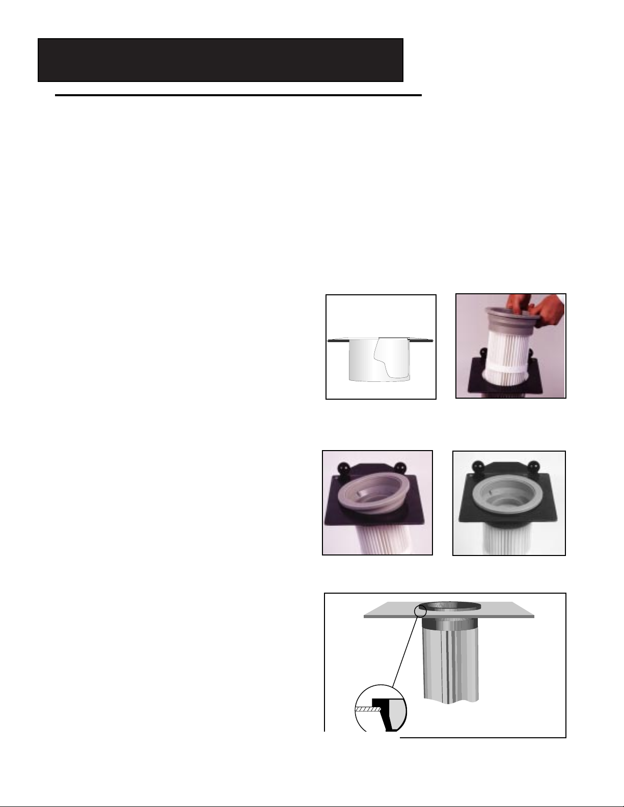
If top load sleeve:Insert the provided installation sleeve in the tubesheet hole to protect the membrane from the rough edges. (Installation
sleeves are located in the box labeled “Open First.”) Lower the
element through the tubesheet hole, slip the installation sleeve off
over the top of the element and complete the installation. (Figure #1)
3. Carefully lift the cartridge filter element and work the
urethane top of the filter element onto the bag cups/venturi
(Figure #2). Protect the media surface during handling and
installation to avoid any damage to the filter media pleats.
4. Gently push the filter element up onto the bag cup/venturi
until the flexible lip in the inner urethane top snaps into place
on the groove in the bag cup/venturi. Pull down slightly or
rotate the element to ensure the internal lip is properly
engaged in the groove (Figure #3).
If properly installed, the urethane top of the element will not
touch the underside of the tubesheet.
2. Loosely install the clamp between the outer groove markings
on the urethane top. The clamp should be on the top, just tight
enough to stay in place. Do not re-install used clamps.
Figure #2
Figure #3 (cutaway)
INSTALLATION
SLEEVE
Figure #1

Operation Procedures for Bottom Load Collectors
• Leave the timer adjustments set as specified by the baghouse manufacturer until operation stabilizes (usually
24-48 hours). We also recommend a precoating agent such as Neutralite®utilized to help establish an initial
control layer. Once operation has stabilized, the time interval between pulses should be adjusted daily until
the longest off-time possible has been attained without exceeding the designed differential pressure.
Excessive pulsing will lead to shortened filter life. Set the pulse on-time at 0.06 - 0.10 seconds.
• The pressure of the compressed air at the baghouse air header should be set and adjusted as follows when
using cartridge filter elements:
The initial setting should be 60 psi. Increase only if the differential pressure cannot be maintained. Then
increase in 5-10 psi increments until it reaches a maximum of 90 psi. If the pressure must be increased further,
contact Camcorp.
• Only dry compressed air should be supplied to the baghouse cleaning system.
• All inlet ducts should be equipped with baffles or deflector plates to prevent high velocity impingement of
the particulate on the filter surface. Dust should never be allowed to build or stand in the hoppers.
• Verification of airflow should be completed after startup of the baghouse. In some cases, the airflow will be
increased if proper airflow dampering or other method of controlling airflow is not utilized. Set the dampers
or fan speed to the minimum required airflow at the ventilation point. If not controlled, increased pressure
drop may occur due to increased grain loading and high gas velocity between filter elements.
5. Center the clamp in the groove in the urethane top.
Using a nut driver, hand tighten the clamp.
Care should be taken when tightening the clamp:
• Do not over tighten. Over tightening may cause a
cutting of the urethane.
• If the urethane material extrudes into the clamp band
notches or around the edge of the clamp, over tightening has occurred.
• Use of “lined” clamp is recommended, which protects the
urethane from damage. Maximum width of the clamp
band is 9/16”.
After tightening, you should not be able to rotate the filter element by hand. Make sure the filter elements hang plumb and
are not touching each other or the collector wall (Figure #4).
Figure #4
INSTALLATION INSTRUCTIONS
Top Load
Filter Elements
-continued-
1. Remove old bags and cages from the collector. The clean air plenum should be thoroughly cleaned after
removing the used bags and cages. Clean the top surface and inside surface of the tubesheet hole so the
urethane top will seal on a clean smooth metal surface. Remove any sharp edges prior to installing the filter elements as they can cause tears in the urethane tops of the filter elements.
Note for TEXusers:The surface of your TEX filter element is very delicate! When moving or
handling, care must be taken to prevent any scraping of the surface. Cardboard or other smooth material
should be placed on or around rough surfaces (such as door frames and handrails) to protect the filtration
surface from damage during handling. Do not stack filter elements more than four high. We recommend
using an installation sleeve to protect the media during installation of the element into tubesheet.
If top load sleeve:Insert the provided installation sleeve in the tubesheet hole to protect the membrane
from the rough edges. (Installation sleeves are located in the box labeled “Open First.”) Lower the
element through the tubesheet hole, slip the installation sleeve off over the top of the element and complete the installation. (Figure #1)Inspect each filter
element for damage from shipping, storage or
handling.
Do not use damaged elements; they may leak or fail
prematurely.
3. Gently push the flexible urethane top of the
filter element on one side until it snaps into
the tubesheet hole (Figure #3). Then push the
opposite side of the top of the element until it
is securely snapped into the tubesheet hole
(Figure #4).
4. The top flange should be
flat on the surface of the tubesheet. Do not use
excessive force or stand on the filter elements to
snap them into place. The groove in the urethane
top of the element should be securely seated in
the tubesheet hole (Figure #5).
2. Slowly lower the filter element T
through the tubesheet hole without touching the
sides of the hole as much as possible (Figure #2).
Hitting the sides can cause damage to the filter
media pleats. Protect the media surface
whenever possible.
Figure #2
Figure #1
Figure #3
Figure #5
Figure #4
INSTALLATION
SLEEVE

Installation of Snapband Retainers for Top Load Filter Elements
NOTE: Asnapband retainer has been shipped with every top load Filter Element. If you do not
have these snapband retainers, call your representative immediately so they can be sent to you for proper
installation.
5. Pinch the snapband retainer in the center to form a figure “8” (Figure #6).
6. Bend the loop slightly and place the retainer under the molded lip of the top flange of the filter element.
This shallow lip prevents upward movement of the snapband retainer after proper installation (Figure #7).
7. With the snapband retainer held against one side of the filter element top interior (Figure 7), slowly allow
the retainer to expand into the recessed area between the lip rim and the three interior post stops.
8. The snapband retainer should fit snugly between the lip rim and the vertical post stops
(Figure 8). Be sure the snapband retainer is level and not installed crooked. Acorrectly installed snapband
retainer will help prevent any potential leakage at the tubesheet and keep the filter element firmly in place.
Operation Procedures for Top Load Collectors
• Leave the timer adjustments set as specified by the baghouse manufacturer until operation stabilizes (usually
24-48 hours). We also recommend a precoating agent such as Neutralite® utilized to help establish an initial
control layer. Once operation has stabilized, the time interval between pulses should be adjusted daily until
the longest off-time possible has been attained without exceeding the designed differential pressure.
Excessive pulsing will lead to shortened filter life. Set the pulse on-time at 0.06 - 0.15 seconds.
• The pressure of the compressed air at the baghouse air header should be set and adjusted as follows when
using filter elements:
The initial setting should be 60 psi. Increase only if the differential pressure cannot be maintained. Then
increase in 5-10 psi increments until it reaches a maximum of 90 psi.
• Only dry compressed air should be supplied to the baghouse cleaning system.
• All inlet ducts should be equipped with baffles or deflector plates to prevent high velocity impingement of
the particulate on the filter surface. Dust should never be allowed to build or stand in the hoppers.
Figure #6
Figure #8
Figure #7
 Loading...