

Page 1

Newton Series®HD MC600HD
High Definition Satellite Speaker User Manual
Page 2
INTRODUCTION
Thanks for choosing a Newton HD Series speaker. The
MC600HD features the finest drivers, precision internal
crossover circuitry, and an elegant enclosure design.
The design team at Cambridge SoundW
is no better combination of audiophile-level attention to
detail and reasonable cost.
AFTER UNPACKING
Store the shipping carton and packing material for future
use and transport.
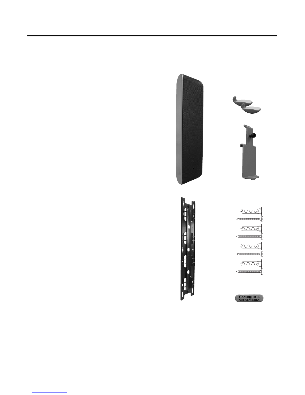
CONTENTS
1. One Speaker
2. Two stick-on rubber feet
3. Center Channel rear support
4. Wall mount bracket
5. Four screws and wall anchors
6. Logo Badge
INSPECTING FOR DAMAGE
Examine each part carefully for shipping damage. If there is
any, do not install or use the speaker. Return the speaker to
the merchant where you made the purchase or call
Cambridge SoundWorks at 1-800 FOR-HIFI (1-800-367-
4434) for assistance.
orks believes there
2.
3.
1.
5.
4.
6.
2
Page 3
SPEAKER PLACEMENT
RECOMMENDED DISTANCE
APART FOR STEREO
20 - 55
ANGLE
APPROX.
EAR LEVEL
MAXIMUM RECOMMENDED DISTANCE
APART FOR HOME THEATER
SURROUND
SPEAKER
SURROUND
SPEAKER
POWERED
SUBWOOFER
CENTER CHANNEL
MAIN SPEAKERS
LEVEL
WITH
CENTER
SPEAKER
140º
140º
110º
110º
30º
30º
7.1 REAR
SPEAKER
7.1 REAR
SPEAKER
MAIN
SPEAKER
MAIN
SPEAKER
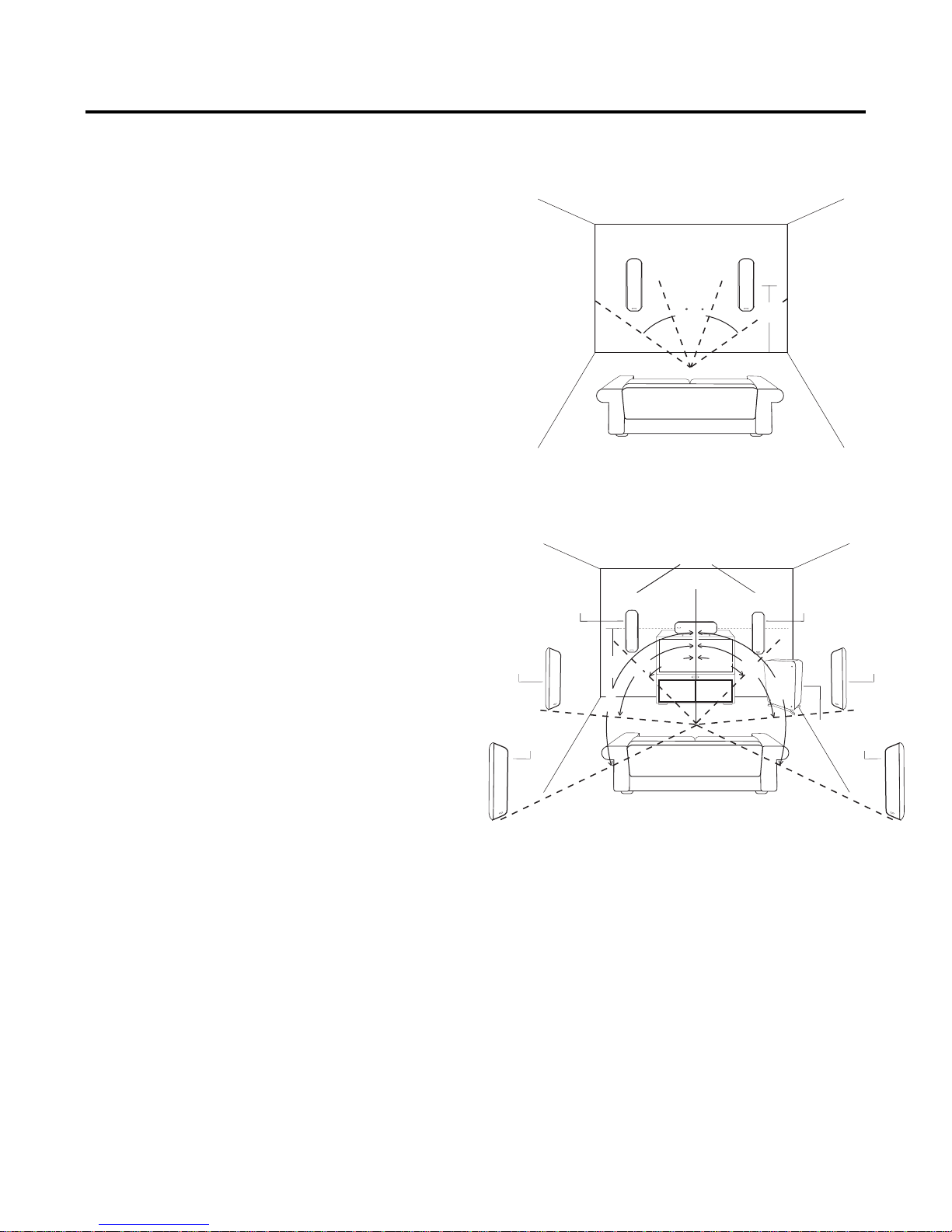
The proper placement of speakers affects how well the AV
surround system recreates the soundfield intended by the
recording engineer. Current recording practice typically
assumes a speaker array with a center channel speaker
directly in front of the central viewing position. Left and right
speakers are placed so they each form a 30 degree angle
from the centerline. Left and right surround speakers should
be 110 degrees from the centerline. Left and right rear
speakers in a 7.1 system should be at 140 degrees. If a single rear speaker is used in a 6.1 system, it should be centered on the rear wall. Front speakers should be as close to
the height of the TV monitor as practical. Surround and rear
speakers should be slightly higher. Recreate this speaker
pattern as closely as your room and furnishings allow.
Don’t be too concerned if your situation and listening environment dictate the speakers’ position. Most rooms do not
allow ideal placement. Place your speakers as close to
these guidelines as practical. The speakers will still provide
convincing, lifelike sound.
Your surround processor has a variety of adjustments to
optimize the sound based on the speakers’ capabilities and
placement. These adjustments vary by processor, so refer to
your processor’s manual for instructions specific to your
equipment. Set your main, center, and surround settings to
“SMALL”, with subwoofer “ON”. If your processor allows you
to adjust the crossover frequency, set it as close to 100Hz
as possible.
void placing front left and right speakers very close to a
A
•
side wall (within 12-14 inches). The reflected sound from the
wall degrades the sound coming directly from the speaker.
3
Page 4
WIRING THE SPEAKERS
If you wish to conceal the wire within the walls, it is easiest
to run the wires to their final positions prior to mounting the
speakers.
The spring loaded terminals of the MC600HD accept bare
wire between AWG #12 and AWG #18 (lower numbers are
thicker). It is not necessary to “tin” the wire or use connectors to terminate the wire.
• Use at least AWG #18 speaker cable for short runs (under
15 feet). Use AWG #16 or heavier speaker cable for
longer runs.
Building codes typically require plenum rated wire for
•
installation within walls. Be sure to use wire that complies
with any applicable local building codes. Plenum rated
cable typically has an outer jacket with individually insulated conductors inside the outer jacket. Some brands of
plenum rated cable may be too thick to fit the space
between the wall mount bracket and the speaker. To use
heavier plenum rated speaker cable with the wall mount
brackets, remove the outer jacket and any filler cord back
to the point where the wire exits the wall.
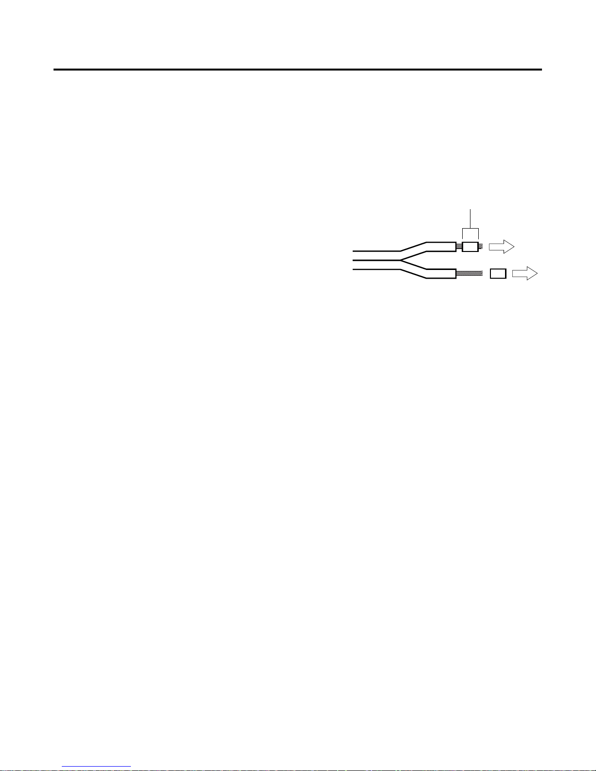
Strip 1/2 inch
Preparing the wires:
Determine how long the speaker cable should be for
1.
each speaker. Cut the speaker cable into the
appropriate lengths.
2. Route the wire to each speaker location.
3. Strip 1/2 inch of insulation from the two individual con-
ductors in the speaker cable. Twist the exposed strands
of bare wire together
4. Determine which conductor you will use to connect the
positive terminals of the amplifier and speaker together
Printing or a ridge on the insulation usually distinguishes
one of the two conductors. Sometimes the metal of the
conductors has two dif
color of each conductor may be different.
.
ferent colors, or the insulation
.
4
Page 5

TO ATTACH THE WIRES
1. Press the speaker’s red terminal to expose the hole in
its shaft.
2. Insert the stripped end of one cable’s positive conductor
into the speaker’s red (+) terminal.
3. Release the terminal to secure the connection. Make
sure no stray strands of wire are present.
4. Repeat the procedure for the cable’s other conductor
and the speaker’s black (–) terminal.
5. Connect the opposite end of the speaker cable to the
speaker outputs of your receiver
observe channel and polarity (Left Positive, Left
Negative, Right Positive, Right Negative).
6. Repeat the process for each speaker.
. Remember to
5
Page 6

SPEAKER MOUNTING
1.
5.
4.
3.
2.
The MC600HD may be wall mounted or placed horizontally
on a table top as a center-channel using the included hardware. Matching floor and table-top stands are available
separately from Cambridge SoundWorks.
Hanging the speaker on the wall:
The MC600 may be mounted either vertically or horizontally
using the supplied wall bracket. Method #1 is recommend
ed. Use Method #2 if there is insufficient clearance for
Method #1.
Method #1 – Use this method when mounting the speaker
vertically when you have at least 21" clearance above the
top of the wall mount bracket. Use this method whenever
mounting the speaker horizontally.
1. Using the wall mount bracket as a guide, mark at least
four locations for mounting screws. It is best to use the
holes at the four outermost corners. If concealing the
wiring in the wall, position the bracket so that the wire
exits the wall through the large hole in the center of the
bracket. The wire should extend through the bracket
approximately 12". Drill a 1/4" diameter hole and install
wall anchors in each location. Refer to the instructions
in the Appendix for proper use of the Toggler brand
anchors included with this speaker.
-
2. Attach the mounting bracket securely to the wall using
four #10 screws.
3. Attach the wire to the speaker terminals. Slide the
speaker on the bracket from the top while guiding the
wire through the channel between the speaker and
bracket.
4. Pull the speaker logo straight out to remove it. Use a
philips screwdriver to gently tighten the lock screw
concealed in the hole behind the logo to secure
speaker to the bracket. Do not over-tighten. It only
requires slight pressure! Pay attention to the wire
location so that the screw does not penetrate the
speaker wire. Install the logo so that the test is upright.
6
Note: Screw is already
installed within speaker.
Use philips screwdriver
to tighten. (See #4)
Page 7

SPEAKER MOUNTING
Method 2 – Use this method to mount the speaker vertically
when you have less that 21" clearance above the top of the
speaker bracket.
speaker horizontally, and whenever at least 21" clearance is
available.
1. Using the wall mount bracket as a guide, mark at least
four locations for mounting screws in the elongated
keyholes found at the four corners and center sides.
It is best to use the holes at the four outermost corners.
If concealing the wiring in the wall, position the bracket
so the wire exits the wall through the large hole in the
center of the bracket. The wire should extend
approximately 12".
2. Drill a 1/4" diameter hole and install plastic anchors in
each location. Refer to the instructions in the Appendix
for proper use of the Toggler brand anchors included
with this speaker.
Always use method #1 when mounting the
3. Insert #10 screws in each anchor and tighten them until
they extend approximately 1/4". Temporarily place the
bracket in place and tighten the four mounting screws
to the point that the bracket can still be be removed.
You should have to supply slight pressure to slide the
bracket back into place between the wall and screws.
4. Pass the wire through the center hole of the bracket.
Attach the wire to the speaker terminals. Slide the
speaker on the bracket from the top while guiding the
wire through the middle of the channel formed between
the speaker and bracket.
5. Pull the speaker logo straight out to remove it. Use a
philips screwdriver to gently tighten the lock screw
concealed in the hole behind the logo to secure the
speaker to the bracket. Do not over-tighten. It only
requires slight pressure! Pay attention to the wire
location so that the screw does not penetrate the
speaker wire. Install the logo with the text upright.
6. Align the speaker and bracket assembly over the four
screws and press downward about 1/2" so that the
screws lock into the keyhole slots in the bracket. Guide
any slack speaker wire back into the wall as you
position the speaker.
Note: Screw is already
installed within speaker.
Use philips screwdriver
to tighten. (See #4)
7
Page 8

HORIZONTAL PLACEMENT
To place horizontally on a tabletop or shelf:
Attach two rubber hook-shaped stick-on feet
1.
symmetrically along the bottom edge of the speaker
approximately 18" apart. If you are mounting the
speaker on an uneven surface you may need to attach
the feet closer to the center
to your needs. You may orient the speaker so that the
terminals are at either end.
. Adapt the actual position
2. Slide the rear support into the channel on the rear of
the speaker until it is in the approximate center of the
speaker. Orient it so the foot is along the same side as
the rubber feet you installed in step 1.
ighten the set-screw finger-tight to stabilize the
3. T
support.
4. Remove the logo by pulling it straight out. Turn it 90
degrees so that the text reads correctly. Press it back
in place.
1.
3.
2.
4.
8
Page 9

SETTING BASS CONTOUR
The switch located near the connection terminals optimizes
the low frequency response of the speaker for wall or stand
mounting.
• When the speaker is mounted on a speaker stand,
away from the wall press the end of the switch marked
with “|”.
• When the speaker is mounted on the wall or table,
press the end of the switch marked with “O”. The upper
bass range will be slightly attenuated to compensate for
the increase in bass caused by wall reflection.
The above recommendations should yield the most accurate
response in each example, but they are optional. If you prefer the sound with settings opposite the above recommendations, feel free to use your settings instead.
Automatic Tweeter Protection
he MC600HD can be safely used with any receiver rated
above 30 watts per channel. There is little advantage in
using more power than 100 watts per speaker, but receivers
above this power rating can be used so long as the receiver
is not operated at distorted levels.
To protect the tweeter, a self-resetting circuit breaker is
incorporated into the MC600HD crossover network. If the
speaker is overpowered for an extended period, this circuit
breaker will open and the tweeter will be disconnected.
When the volume is reduced or the overload has passed,
the circuit will reset and normal operation will be restored.
9
Page 10

SPECIFICATIONS
2a
2b
1
1/4"
BRAND
AF6TMALLIGATOR
®
Solid-Wall Anchors
Drill 1/4" diameter hole — minimum hole
depth 1
1
/2". Insert anchor and tap flush.
Place item over anchor. Insert screw and
tighten flush. For best results use screw
gun for installation in solid walls.
In walls of minimum thickness 3/8",
screw opens anchor and locks securely.
Patented under U.S. Patent Nos. 4,752,170 and
5,161,296; and foreign counterparts thereof.
Other patents pending. TOGGLER and typeface,
and ALLIGATOR are worldwide registered
trademarks of Mechanical Plastics Corp.
© 2002 MPC
®
2a
2b
1
BRAND
AF6TMALLIGATOR
®
Solid-Wall Anchors
Drill 1/4" diameter hole — minimum hole
depth 1
1
/2". Insert anchor and tap flush.
Place item over anchor. Insert screw and
tighten flush. For best results use screw
gun for installation in solid walls.
In walls of minimum thickness 3/8",
screw opens anchor and locks securely.
Patented under U.S. Patent Nos. 4,752,170 and
5,161,296; and foreign counterparts thereof.
Other patents pending. TOGGLER and typeface,
and ALLIGATOR are worldwide registered
trademarks of Mechanical Plastics Corp.
© 2002 MPC
®
Warning About Excessive Amplifier Distortion:
Operating a receiver (of any power rating) beyond its maximum undistorted output level creates distortion – added
high frequency sound not part of the musical program.
Distortion dramatically increases the internal operating temperature of a speaker and will eventually cause the speak
er’s failure due to burned or melted internal parts. While
Cambridge SoundWorks includes the most heat-tolerant
parts commensurate with good acoustic design, the speaker’s Limited Warranty against defects in materials or workmanship does not apply to parts that fail from long-term
operation at very high temperatures.
Enclosure Cleaning
The speaker enclosures can be cleaned with a soft, damp
cloth or mild cleaner.
Brush or vacuum the grille panels with a soft brush attachment to your vacuum cleaner.
Specifications
Appendix
-
Dimensions: 25-3/8" H x 7-1/8" W x 3-15/16" D
Weight: 14-1/2 pounds each
Impedance: nominal 8 ohms
Recommended amplifier power range: 20W – 100W RMS
per channel.
Frequency Range: 80Hz – 24kHz.
Woofer Type: 4 x 3-1/2" with co-injection molded composite
cones and butyl-rubber surrounds.
Tweeter Type: 1/2" aluminum dome with ferrofluid-damping
and neodymium magnet.
Crossover: 2-1/2 way, series-connected with selectable
wall-mounting compensation.
Enclosure: High-density pressure-cast aluminum with
molded-composite baf
fle.
10
Page 11

WARRANTY
11
Page 12

P81-2190
 Loading...