

Page 1
DVD PLAYER/TUNER – PREAMPLIFIER
USER MANUAL
®
Page 2
2
The lightning flash with arrowhead,
within an equilateral triangle, is intended
to alert the user to the presence of
uninsulated “dangerous voltage” within
the product’s enclosure that may be of
sufficient magnitude to constitute risk
of electric shock to persons.
The exclamation point within an equilateral triangle is intended to alert the user
to the presence of important operating
and maintenance (servicing) instructions
in the literature accompanying this
product.
WARNING
DO NOT OPEN
TO PREVENT THE RISK OF ELECTRIC
SHOCK, DO NOT REMOVE
SPEAKER’S COVER. NO USER-
SERVICEABLE PARTS INSIDE.
REFER SERVICING TO QUALIFIED
SERVICE PERSONNEL.
AVISIQUE
POUR EVITER TOUT RISQUE DE
CHOC ELECTRIQUE, NE PAS
DEMONTER LE COUVERCLE DU
HAUT PARLEUR. AUCUN ENTRETIEN DES PIECES INTERIEURES
N’EST REQUIS.TOUT SERVICE
D’ENTRETIEN NE DOIT ETRE
EFFECTUE QUE PAR DU PERSON-
NEL D’ENTRETIEN QUALIFIE.
READ AND HEED IMPORTANT SAFETY WARNING
ON REAR OF ENCLOSURE
CAUTION:
TO PREVENT ELECTRIC SHOCK, MATCH WIDE
BLADE OF PLUG TO WIDE SLOT, INSERT FULLY.
ATTENTION:
POUR EVITER LES CHOCS ELECTRIQUES, INTRODUIRE LA LAME LA PLUS LARGE DE LA FICHE
DANS LA BORNE CORRESPONDANTE DE LA PRISE
ET POUSSER JUSQU’AU FOND.
IMPORTANT NOTICE:
THE SERIAL NUMBER FOR THE PRODUCT IS
LOCATED ON THE REAR PANEL. PLEASE WRITE
THIS NUMBER DOWN AND KEEP IT IN A SECURE
AREA. THIS IS FOR YOUR SECURITY.
Page 3

3
IMPORTANT SAFETY INSTRUCTIONS
POWER-CORD PROTECTION – The AC power cord
should be routed so that it is not likely to be walked
on. No object should bring weight to bear on to the AC
power cord.
LIGHTNING – For added protection for this product
during a lightning storm, or when it is left unattended
and unused for long periods of time, unplug it from the
wall outlet. This will prevent damage to the product
due to lightning and power-line surges.
OVERLOADING – Do not overload wall outlets, extension cords, or integral convenience outlets as this can
result in a risk of fire or electric shock.
OBJECT AND LIQUID ENTRY – Never use probes of
any kind to reach into the product as they may touch
dangerous voltage points or short parts that could
result in a fire or electric shock. Never spill liquid of
any kind onto the product.
SERVICING – Do not attempt to service the product
yourself as opening or removing the cover may expose
you to dangerous voltage or other hazards. Refer all
servicing to qualified service personnel.
DAMAGE REQUIRING SERVICE – Immediately
unplug the product from the wall outlet or other power
source and refer servicing to qualified service personnel under the following conditions:
a) When the power-cord or plug is damaged.
b) If liquid has been spilled, or objects have fallen into
the product.
c) If the product has been exposed to rain or water.
d) If the product does not operate normally by follow-
ing the operating instructions; or exhibits a distinct
change in performance.
e) If the product has been dropped or damaged in
any way.
REPLACEMENT PARTS – When replacement parts
are required, be sure the service technician uses
replacement parts specified by Cambridge
SoundWorks, or ones which have the same characteristics as the original part. Substandard substitutions
may result in fire, electric shock, or other hazards.
SAFETY CHECK – Upon completion of any service or
repairs, ask the service technician to perform safety
checks to determine that the product is in proper
operating condition.
READ INSTRUCTIONS – All safety and operating
instructions should be read before the product is
operated.
RETAIN INSTRUCTIONS – The safety and operating
instructions should be retained for future reference.
HEED WARNINGS – All warnings on the product and
in the operating instructions should be adhered to.
FOLLOW INSTRUCTIONS – All operating and use
instructions should be followed.
CLEANING – Unplug the product from the wall outlet or
other power source before cleaning. Use a dry cloth
for cleaning.
ATTACHMENTS – Do not use any adapters or attachments not recommended by Cambridge SoundWorks
as they may cause hazards.
WATER AND MOISTURE – Do not use the product
near water - for example, near a bath tub, wash bowl,
kitchen sink, or laundry tub; in a wet basement; or near
a swimming pool or other similar areas.
ACCESSORIES – Do not place the product on an
unstable cart, stand, tripod, bracket, or table. The
product may fall, causing serious injury to a child or
adult and serious damage to the product.
VENTILATION – Any slots, openings and metal fins
provided for ventilation must not be blocked or covered
such as by placing the product on a bed, sofa, deep
pile rug, or other similar surface. The product should
not be placed in a built-in installation such as a bookcase or rack unless sufficient clearance is maintained
to provide adequate ventilation.
HEAT – The product should be situated away from heat
sources such as radiators, heat registers, stoves, and
other products (including amplifiers) that produce heat.
POWER SOURCE – The product should be operated
only from the type of power source indicated on the
rear panel. If you are not sure of the type of power supply to your home, consult your dealer or local power
company.
POLARIZATION – The product is equipped with a
polarized alternating-current plug (a plug having one
blade wider than the other). This plug will fit into the
power outlet only one way. This is a safety feature. If
you are unable to insert the plug fully into the outlet, try
reversing the plug. If the plug should still fail to fit, contact your electrician to replace your obsolete outlet. Do
not defeat the safety purpose of the polarized plug.
Page 4

4
DISC PRECAUTIONS:
MOISTURE OR DEW – May occur if the product is
suddenly moved from a cold environment to a warm
one, and prevent it from reading the disc. If this happens, turn the product on for a least one hour before
inserting a disc.
DAMAGED DISCS – Never play cracked, warped, or
otherwise damaged discs as they may harm the drive
mechanism.
HANDLING DISCS –
• Do not touch the play side of the disc. Always
handle the disc by the edges.
• Do not attach paper, tape or labels to the disc
except for purpose-designed CD labels applied with
an applicator intended for the purpose. Out of balance discs may damage the mechanism.
• Keep discs away from direct sunlight and
excessive heat.
• Keep disc in proper storage cases when not in use.
DISC CLEANING –
• Before playback, wipe the play surface of the disc
outwards from the center with a clean, soft, lint-free
cloth.
STATEMENT OF COMPLIANCE – This equipment has
been tested and found to comply with the limits for a
Class B Digital device pursuant to Part 15 of the FCC
Rules. These limits are designed to provide reasonable protection against harmful interference in a residential installation. This equipment generates, uses,
and can radiate radio frequency energy and, if not
installed and used in accordance with the instructions,
may cause harmful interference to radio communications. However, this is no guarantee that interference
will not occur in a particular installation. If this equipment does cause harmful interference to radio or television reception, which can be determined by turning
the equipment off and on, you are encouraged to try to
correct the interference by one or more of the following
measures:
• Reorient or relocate the receiving antenna and the
power cord.
• Increase the separation between the equipment and
the receiver.
• Connect the equipment to an outlet on a different circuit than the one to which the receiver is connected.
• Consult the dealer or an experienced radio/TV technician for help.
This product is manufactured under license from
Dolby laboratories, “DOLBY”, “AC-3”, “Pro Logic” and
the double-D symbol are trademarks of Dolby laboratories. Copyright 1992-1997, Dolby laboratories.
This Product incorporates copyright protection technology that is protected by method claims of certain
U.S. Patents and other intellectual property rights
owned by Macrovision Corporation and other rights
owners. Use of this copyright protection technology
must be authorized by Macrovision Corporation, and is
intended for home and other limited viewing uses only
unless otherwise authorized by Macrovision
Corporation. Reverse engineering or disassembly is
prohibited.
Page 5

5
Page 6

6
TABLE OF CONTENTS
Introduction ................................................................7
Carton Contents..........................................................8
Remote Control ..........................................................9
Front Panel and Display ..........................................12
Getting Started ........................................................13
System Connection Diagrams..................................14
Basic Setup Menu ....................................................19
Operation and Use ..................................................22
Advanced Operation ................................................27
Advanced Setup ......................................................29
Specifications ..........................................................36
Limited Warranty ......................................................37
Page 7

7
INTRODUCTION
Thanks for choosing the MegaTheater AVS500 as the
heart of your home theater system. We at Cambridge
SoundWorks believe that it is the ideal utilization of
high technology to simplify the home entertainment
experience.
The AVS500 will entertain you for many years with its
flawless DVD playback, sensitive AM and FM radio
reception, and playback of normal CD, CD+G, HDCD
and compressed music files on DVD-R, CD-R, or
CD-RW discs. It will also play back VCD and SVCD
discs you burn on your PC from video files such as
home movies from your digital camcorder. In addition,
the AVS500 will display your JPEG digital still photos
from CD on your TV screen. You can even produce a
slide show with musical background by saving your photos and background music MP3 file on the same disc.
The AVS500 includes all the inputs and outputs necessary for the most common home theater system
needs. There are two sets of rear panel A/V inputs and
outputs which can be used to connect a VCR and a
satellite receiver or cable box. A third front panel input
and output can be used for quick connection of a
camcorder video game, or portable music player. An
optical digital input is also provided to connect the
Dolby Digital 5.1 signal from a cable TV set top box or
a satellite receiver equipped with an optical digital output. The built-in Dolby Digital and DTS 5.1 surround
decoders will accurately play back any contemporary
DVD when connected to a suitably powered loudspeaker system or multichannel power amplifier.
Because of its stereo and Virtual Surround modes, the
AVS500 can also be used with a stereo TV or with
powered 2.0 or 2.1 speaker systems.
Finally, the AVS500 is compatible with High Definition
TV monitors thanks to its advanced progressive scan
circuitry. This unique circuit analyzes the characteristics of the source material on DVD and automatically
selects the proper de-interlacing algorithm for fast
motion or still scenes, as well as 3:2 pulldown to convert the 24 frame per second rate of film sources to
video’s 60 frames per second. The result is the clearest, sharpest picture – totally free of motion artifacts or
the visual stutter sometimes seen when movies, or
movie segments originally shot on film, are converted
to video.
If You Are New To Digital Discs
DVDs are divided into one or more sections called
“Titles.” Each title has a numerical label displayed on
the front panel Vacuum Flourescent Display (VFD). You
can select the different titles using the title key on the
remote control, or by using the Playback Control (PBC)
function. The ability to bypass titles on a particular
DVD is controlled by the maker of the specific DVD,
and may not be available on all DVDs.
Each title is divided further into “Chapters.” You may
navigate chapters using the skip keys
( |<<, >>| ), directly using the numerical keypad, or
within the DVD’s on-screen menu.
CD and VCD discs are divided in tracks. You may
select them using the skip keys or the numeric keypad. MP3 and Picture CDs are organized in files contained within folders. Use the on-screen “Smart Nav”
function to select the files you wish to play.
The selection of many features of DVD playback is
automated by “flags” in the digital bitstream that let the
disc producer tell your player the optimum playback
mode. The AVS500 will respond to these flags where
appropriate and automatically select the proper
soundtrack or technique for producing a progressive
scan picture on high definition TV sets.
Page 8
8
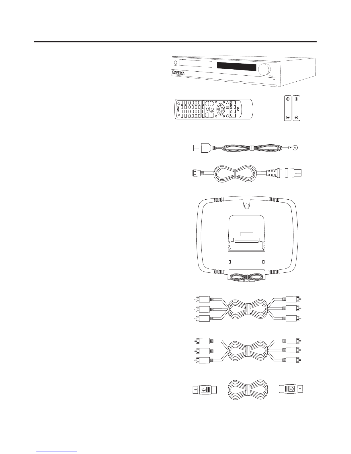
CARTON CONTENTS
A) One AVS500 main control unit.
B) Remote control
C) Two AAA Batteries
D) FM Antenna
E) FM antenna to F-connector adapter cable.
F) AM Loop antenna
G) AV cable with three RCA plugs
(red, white, yellow) on each end.
H) Component video cable with three RCA plugs
(red, green and blue) on each end.
I) S-Video cable
EJECT/LOAD
SUBTITLE ANGLE REPEAT A-B/MUSIC
STANDBY
AUDIO J PEG SH UFFLE SLIDE
DVD
PROLOGIC
SPDIF TUNER
ENTER
MUTE
TITLE
CH
+
–
CH
AV1 AV2 AV3
OSD
321
654
987
GOTO+100
PBC
PROGRAM
CLEAR/EQ
VOL SETUP
MENU SETUP
VOL
+
–
VOL
ZOOM STOP
RETURN RESUME SLOW
AM/FM
STEP
SAVE
PAUSE PLAY
– AUTO +– TUNE +
– PRESET +
A
B
E
C
F
G
H
I
D
Page 9
9
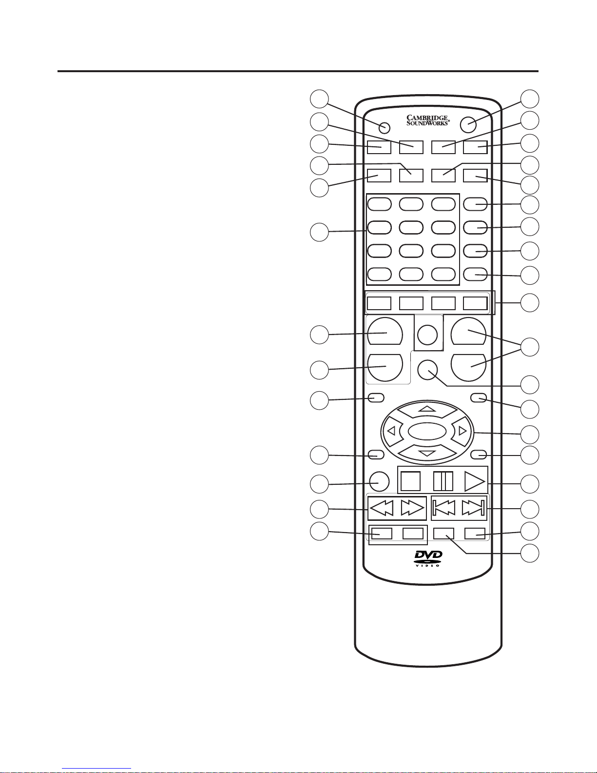
REMOTE CONTROL
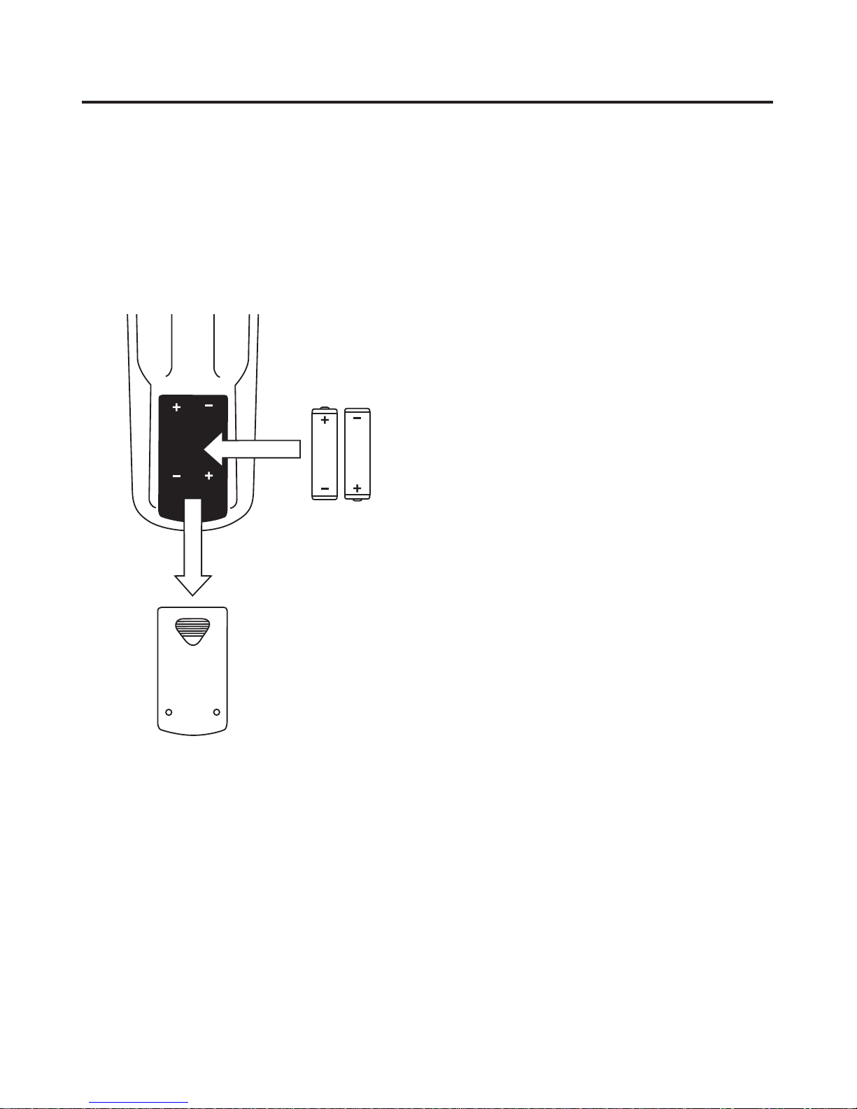
Installing The Remote Control Batteries
Open the lid of battery chamber under the remote control, and install the two AAA batteries (included).
Observe and follow the polarity marks. Replace the lid.
When the batteries become weak, replace them immediately. Old batteries may leak highly corrosive fluid
and permanently damage the remote control.
Button Locations and Functions
Most operation of the AVS500 is done using the remote
control. Basic controls are provided on the front panel
for emergency use in the event of battery failure or a
lost remote.
1. STANDBY: Use this to turn the AVS500 on and off
for normal use. (The front panel power switch
should normally be left on.)
2. REPEAT: Repeats a chapter or title on DVD, and
disc or track on CD.
3. A-B / MUSIC: Repeats a user-defined section of a
DVD, CD or MP3 file. Press the button once at the
start of the section you wish to repeat, press it
again at the end of the selection. Press the button
again to cancel A-B repeat. In Slide Show mode,
this key is used to select the background music file
if desired.
4. SHUFFLE: Selects CD and MP3 music tracks in
random order.
5. SLIDE: Selects slideshow mode, which will play a
selection of JPEG photos on CD in sequence.
6. OSD: When playing a DVD, press once to show an
On-Screen Display of the current title and chapter.
Press again to display the remaining time. Press a
third time to display chapter elapsed time. Press a
fourth time to display chapter remaining time. A fifth
press will turn the On Screen Display off.
For all CD, VCD, SVCD discs, press once for single
track elapsed time. Press again for single track
remaining time. Press a third time for total elapsed
time. The fourth press displays total remaining time,
and the fifth press turns the OSD off.
For MP3 discs, one press displays file elapsed
time, the second press turns the OSD off.
7. PBC: This key toggles the Playback Control state.
Normal default operation is PBC ON.
• With PBC on, disc play uses the DVD menu, and
conventional 0n-screen navigation controls.
• With PBC off, you see an information display showing the contents of the disk. It includes the number
of titles, tracks, total time, audio streams, and subpicture streams. It also shows the encoding standard, video format, and languages and sound
options.
You have direct access to titles and tracks of the
disc. Use the number keys to select the desired
title (DVD) or track, (VCD, CD).
8. PROGRAM: When in PBC OFF mode with the disc
stopped, you may program a playing sequence.
Page 10
10
9. CLEAR/EQ: Clears the last entry while programming. Selects Graphic Equalizer mode at all other
times. See the Advanced Operation section for
equalizer operation.
10.INPUT SELECTOR: Press the button corresponding
to the desired input source. Use the DVD button to
select any disc inside the AVS500 (DVD, VCD, CD,
CD-ROM with JPEG or MP3 files).
11.VOLUME: Press to adjust volume level from 00
(Minimum) to 32 (Maximum). The level is displayed
on the OSD and on the front panel.
12.MUTE: Press to toggle between muted and nonmuted state.
13.VOL SETUP: Press to enter the Volume Setup
menu. You may adjust each individual channel volume level while listening. You may also adjust bass
and treble from this menu. Press this button again
to exit the menu.
14.CURSER CONTROL: Press these buttons to navigate through menus. Use the ENTER key to make
your selection.
15.SETUP: Use to enter the AVS500 main setup
menus. Disc play will stop when selected. Press the
button again to exit the menu when you are done.
16.TRANSPORT CONTROLS: Use to start, stop, or
pause disc playback.
• For DVD press the STOP key once, the unit enters
“memory stop.” Play resumes from the same point
when PLAY is pressed. Press STOP a second time
to resume from the disc’s beginning with the next
press of PLAY.
17.|<< and >>| / –AUTO +:
• Disc play – Selects PREVIOUS or NEXT track or
Chapter.
• Tuner – Auto tunes to the next lower or
higher station.
18.STEP/SAVE: Each press advances one frame in
DVD mode. Press to save a tuned radio station into
the currently selected preset location.
EJECT/LOAD
SUBTITLE ANGLE REPEAT A-B/MUSIC
STANDBY
AUDIO JPEG SHUFFLE SLIDE
DVD
PROLOGIC
SPDIF TUNER
ENTER
MUTE
TITLE
CH
+
–
CH
AV1 AV2 AV3
OSD
321
654
987
GOTO+100
PBC
PROGRAM
CLEAR/EQ
VOL SETUP
MENU SETUP
VOL
+
–
VOL
ZOOM STOP
RETURN RESUME SLOW
AM/FM
STEP
SAVE
PAUSE PLAY
– AUTO +– TUNE +
– PRESET +
2
3
4
5
6
7
8
9
10
11
12
13
14
15
16
17
18
19
1
32
31
30
29
28
27
26
25
24
23
22
21
20
Page 11

11
27.NUMBER KEYS: Use for direct access to chapters,
titles, and tracks (not all discs allow direct access).
You may also start a disc from a particular title and
chapter, or at a particular time.
• To skip to a track or chapter while playing a disc
press GOTO, then select the track or chapter number desired (use +10 key for tracks above 9), then
press ENTER.
• To start playing a specific title at a specific chapter,
press GOTO, then use the < > keys to highlight the
title. Enter the desired title number using the number keys. Use the < > keys to highlight the desired
chapter and enter this using the number keys.
Press ENTER and the disc will begin playing from
the point you selected.
• To start playing a disc from a specific time, press
GOTO twice. Use the < > keys to highlight Title and
select a title number using the number keys. Use
the < > keys to highlight Time and enter it using the
number keys. You must enter a 0 first for hours less
than 10. Press ENTER and play will begin from
your selected time.
28.AUDIO: This button selects one of the audio
streams available on a DVD. Some DVDs only allow
selection of the audio stream from the DVD menu.
29.JPEG: This button selects the mode used to transition between JPEG still pictures.
30.SUBTITLE: Selects different subtitles available on
the DVD. Not all DVDs support subtitle selection
from this key.
31.ANGLE: Selects different view angles. Very few
DVDs support this feature.
32.EJECT/LOAD: Press to eject the disc tray, or to load
the disc tray.
19.SLOW/AM/FM:
• DVD, VCD, SVCD – Press to engage in slow motion
playback. The first press is 2x Slow (i.e.1/2 normal
speed), the second press is 4x, third press is 6x,
and the fourth press is 8x. A fifth press returns to
normal speed.
• Tuner – Toggles between AM and FM band.
20.PRESET
+,
PRESET –: Use these keys to select a
specific preset location for a radio station.
21.<< and >> /–TUNE +:
• Disc play – Each press selects 2x, 4x, 6x, 8x fast
play mode. The fifth press returns to normal speed.
• Tuner – Manually tune.
22.ZOOM: Each successive press zooms the
image 1.5x, 2x, and 3x. Press again to revert
to normal size.
23.MENU: Press to select the disc menu for the current title. This may vary depending on how the particular disc is mastered. If there is no menu level,
this button will select the current title.
24.TITLE: The unit will return to the disc title page. You
may navigate and make your selection using the
CURSOR, ENTER and PLAY keys.
25.CH –/ PRO LOGIC:
• Tuner mode: Selects next lower station preset.
• Auxiliary A/V input mode: Toggles between
STEREO and PROLOGIC for analog sources, and
for music playback from CD or MP3. Note: When
using an external digital source, surround modes are
automatically selected as with DVD playback.
26.CH +/ SPDIF:
• Tuner mode: Selects the next higher station preset.
• Auxiliary A/V input mode: Toggles between Analog
and Digital (SPDIF) input for a selected input.
Note: The A/V input must be in STEREO mode.
Page 12
12
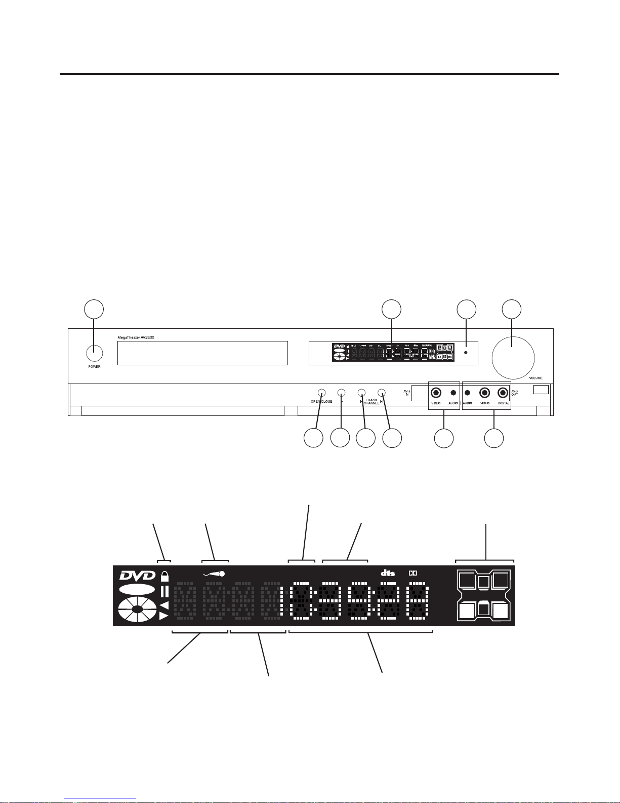
FRONT PANEL AND DISPLAY
VIDEO
1. POWER – Turns main AC power on and off. Leave
on for normal operation, use the remote control to
switch the unit to standby mode when you are not
using it. It is only necessary to turn off this power
switch when you are leaving the unit for extended
periods, such as when you go on vacation, or for
added protection during electrical storms.
2. VFD – Vacuum Fluorescent Display of player status.
3. POWER LED – Indicates the presence of AC power.
This will remain lit in standby mode when the main
power switch is engaged.
4. VOLUME – Controls volume in 32 steps.
5. OPEN/CLOSE – Opens and closes the disc drawer.
6. PLAY – Starts play of the disc.
7. PREVIOUS TRACK/CHANNEL – Selects previous
track on a disc, or selects the next lower radio preset.
8. NEXT TRACK/CHANNEL – Selects the next disc
track or the next higher radio preset.
9. AV3 IN – Composite video and stereo analog audio
inputs for external AV source.
10.AV3 OUT – Composite audio, stereo analog audio,
and Coaxial digital output.
1
2
3
4
5
6
7
8
9
10
VIDEO
TITLE CHP
ST.
TUNED
3D
RDS
DIGITAL
KHz
MHz
L
R
C
LS
RS
S
Parental Lock
Indicator
Not used in
US model
Not used in
US model
Speaker
Format
Indicator
AM/FM
Tuned
Indicator
DVD: Title
RADIO: Preset Number
DVD: Chapter
RADIO: Band
DVD: Time
RADIO: Station Frequency
Page 13
13
GETTING STARTED
There are two stages to an efficient setup and installation of the MegaTheater system.
Stage 1 is the placement and connection of all the
components. We have made this as easy as possible
by color coding all of the critical connections.
Stage 2 is set-up and adjustment, where you tell the
AVS500 what type of TV set you have, and fine tune
the speakers according to their type and placement.
You may also set up parental controls and adjust tone
or equalization preferences at this time.
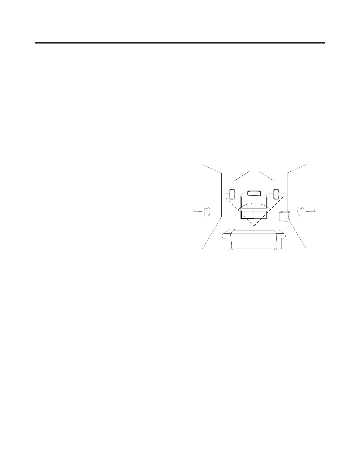
Arranging the Components:
The arrangement of the speakers within the room significantly influences their performance. Here are a few
guidelines to help you get the most from your system.
• The TV monitor is the focal point of any home theater
system. The front left and right speakers should be
placed symmetrically a few feet to either side of the
TV. These speakers should be no farther apart than
the distance of the listener to the speakers.
• The center channel speaker should be placed
directly above or below the TV, and ideally at the
same distance from the listener as the left and right
speakers. Placing the front left, front right, and center speakers at the same height is preferred.
• The surround speakers should be placed on the
side walls, slightly to the rear of the listening position. Ideally they should face each other and be at
a level about 2-3 feet higher than the listeners’
ears. If that is not possible, they may be placed on
the rear wall facing forward.
• The subwoofer is best placed in the front half of the
room, near the plane of the front speakers. Placing
the subwoofer in a corner will provide the most efficient coupling of the subwoofer’s energy to the
room. Positioning the subwoofer away from the
walls will reduce its output. Room acoustics play a
major role in the propagation of bass notes, so it is
advisable to experiment with a variety of placement
options and stick with the one that gives the
strongest bass with the most even response
throughout the room.
• The remote control needs a clear line of sight to the
AVS500’s front panel.
MAXIMUM RECOMMENDED DISTANCE
APART FOR HOME THEATER
SURROUND
SPEAKER
SURROUND
SPEAKER
POWERED
SUBWOOFER
CENTER CHANNEL
MAIN SPEAKERS
45 ANGLE
LEVEL
WITH
CENTER
SPEAKER
Page 14

14
Determining Your System Setup:
There are a variety of system configurations you can
select, depending on the other equipment you wish to
connect to your MegaTheater system.
Option A: The simplest system consists of the
MegaTheater and a TV set. A cable box or satellite
receiver connects directly to your TV in this setup.
Connect the video output from the MegaTheater to your
TV to watch DVD movies. Connect the TV sound output
to an auxilliary A/V input of the AVS500. Select this
same auxiliary A/V input to listen to your off-air, cable,
or satellite programs in Stereo, Virtual Surround Sound,
or Dolby Pro Logic Surround using the AVS500 processor and speaker system.
14
SYSTEM CONNECTION DIAGRAMS
AV-1 IN
AV-2 IN
AV-1 OUT
AV-2 OUT
FM 75Ω
AM 300Ω
VIDEO
LR
S-VIDEO
OUTPUT
DIGITAL
INPUT
DIGITAL
OUTPUT
Y
Cb/Pb
Cr/Pr
5.1
OUTPUT
TO REDUCE THE RISK OF ELECTRIC SHOCK, DO NOT
REMOVE COVER OR BACK. NO USER-SERVICABLE
PARTS INSIDE. REFER SERVICING TO QUALIFIED PERSONNEL.
CAUTION:
CAUTION
ATTENTION
RISK OF ELECTRIC SHOCK
DO NOT OPEN
RISQUE DE CHOC ELECTRIQUE
NE PAS OUVRIR
THIS DEVICE COMPLIES WITH PART 15 OF THE FCC RULES. OPERATION IS SUBJECT
TO THE CONDITION THAT THIS DEVICE DOES NOT CAUSE HARMFUL INTERFERENCE.
®
®
LIS TED
AUD IO SYS TEM
50L K
DESIGNED BY
CAMBRIDGE SOUNDWORKS, INC.
WESTWOOD, MASSACHUSETTS USA 02090
800-367-4434 USA
978-623-4400 OUTSIDE USA
MADE IN CHINA
90-245V AC,
50/60Hz, 68W
AVS500
CLASS 1 LASER PRODUCT THIS PRODUCT COMPLIES WITH DHHS RULES 21CFR,
SUBCHAPTER J, APPLICABLE AT TIME OF MANUFACTURE.
COMPONENT
RF
CENTER
RR
SUB
LF
LR
AUDIO OUT
OUTPUT
INPUT
V
L
R
A
B
V
L
R
COMPOSITE
S-VIDEO
RF IN
RF OUT
ANTENNA
INPUT
AUDIO
OUT
COMPONENT
VIDEO INPUT
Y
Cb/Pb
Cr/Pr
INPUTS
Cable Box
TV
AVS500
VCR or Hard
Disk Recorder
Use this diagram if:
A. You do not have a cable box or satellite receiver and
use your TV tuner to select channels.
B. You have a basic cable box connected to your TV by
the antenna connection (You tune your TV to channel
3 or 4 to view cable channels).
This cable is not reuired
if your TV accepts
S-Video or Component
Video AND you do not
have any additional
sources (such as a VCR)
attached to the AVS500.
This cable is not
required if your TV
accepts Component
Video input.
from cable
Page 15

15
Option B: This option is the best choice if you have a
video source with an optical digital output that offers
Dolby Digital programming (Digital Set Top Box (STB)
for cable, digital Satellite, or an HDTV tuner). The
Digital output of the STB connects directly to the
AVS500. The AVS500 processor decodes the Dolby
Digital signal from your STB when present, and plays
the sound in Stereo, Virtual Surround Sound, or Dolby
Pro Logic otherwise. The Video output of the STB may
be connected either to the AVS500 or directly to the
TV, whichever you prefer. An HDTV tuner STB must be
connected directly to the TV to get High Definition
video. Note: Before making any connections, turn off the
power to all system components. Only turn the power
back on after all connections are made.
15
AV-1 IN
AV-2 IN
AV-1 OUT AV-2 OUT
FM 75Ω
AM 300Ω
VIDEO
LR
S-VIDEO
OUTPUT
DIGITAL
INPUT
DIGITAL
OUTPUT
Y
Cb/Pb
Cr/Pr
5.1
OUTPUT
TO REDUCE THE RISK OF ELECTRIC SHOCK, DO NOT
REMOVE COVER OR BACK. NO USER-SERVICABLE
PARTS INSIDE. REFER SERVICING TO QUALIFIED PERSONNEL.
CAUTION:
CAUTION
ATTENTION
RISK OF ELECTRIC SHOCK
DO NOT OPEN
RISQUE DE CHOC ELECTRIQUE
NE PAS OUVRIR
THIS DEVICE COMPLIES WITH PART 15 OF THE FCC RULES. OPERATION IS SUBJECT
TO THE CONDITION THAT THIS DEVICE DOES NOT CAUSE HARMFUL INTERFERENCE.
®
®
LI STE D
AU DIO SY STE M
50 LK
DESIGNED BY
CAMBRIDGE SOUNDWORKS, INC.
WESTWOOD, MASSACHUSETTS USA 02090
800-367-4434 USA
978-623-4400 OUTSIDE USA
MADE IN CHINA
90-245V AC,
50/60Hz, 68W
AVS500
CLASS 1 LASER PRODUCT THIS PRODUCT COMPLIES WITH DHHS RULES 21CFR,
SUBCHAPTER J, APPLICABLE AT TIME OF MANUFACTURE.
COMPONENT
RF
CENTER
RR
SUB
LF
LR
AUDIO OUT
OUT
IN
V
L
R
A
B
V
L
R
INPUT
S-VIDEO
Y
Cb/Pb
Cr/Pr
COMPONENT
VIDEO INPUT
V
L
R
DIGITAL
OUT
VCR or
Hard Disk Recorder
Cable Box or Satellite Receiver
Composite Video cable is required if you
have auxiliary A/V sources. It is not required
for S-Video or Component Video-capable
TV sets if no auxiliary A/V sources are used.
Use this diagram if:
A. You have a cable box or satellite receiver with digital
or stereo output.
B. You have a VCR and wish to record or play in Stereo
or Pro Logic mode.
TV
AVS500
Page 16

161616
Connecting the Video Output
of the AVS500 To Your TV:
The video output connection you need is determined
by the capability of your TV.
If you have a newer TV with progressive scan (Y/Pb/Pr)
or interlaced (Y/Cb/Cr) component video inputs, use
them for the best picture from DVD playback.
High Definition (HD) and Enhanced Definition (ED)
TV’s should be compatible with the progressive scan
output. Standard Definition TV’s are not.
Note: The component video output of the AVS500 is set
to INTERLACED at the factory. To benefit from a progressive scan TV, you must change the output mode to
PROGRESSIVE in the Setup menu of the AVS500.
If you do not have component video inputs on your TV,
S-Video is the next best choice. Most current TVs have
at least one S-Video input.
Connect one end of the supplied S-Video cable to the
jack on the AVS500, and the other end to the TV’s
S-Video input.
The most common video input type on a TV is
Composite video, also known as CVBS. This input
uses a standard RCA jack, usually color-coded yellow.
The AVS500 has two composite video output jacks on
the rear panel, labeled AV1 and AV2. Either one may
be used. The second output is provided to connect to
the input of a VCR or other device. Note: The AVS500’s
Component and/or S-Video output functions only during
DVD playback. You must also connect the AVS500’s
Composite output to your TV set. It supplies the signal
from an auxiliary A/V source, such as a VCR or cable
box connected to an A/V input of the AVS500. Select a
composite video input on your TV to view the auxiliary
A/V source.
The AVS500 provides output to either it’s Composite
Video or S-Video outputs.
If you do not have any additional A/V sources connected to the AVS500, and you are using the Component
or S-Video outputs, you do not need to connect anything to the Composite outputs of the AVS500.
Note: Progressive Scan mode does not apply to S-Video
or Composite video outputs.
A
B
V
L
R
A/V INPUTS
S-VIDEO
COMPONENT
Y
Cb/Pb
Cr/Pr
Composite Video input
Example of TV set
A/V input panel.
Exact layout and
features will vary
by model.
Page 17

1717
Connecting Auxiliary A/V Sources:
There are three auxiliary A/V connections available on
the AVS500 (AV1, AV2, and AV3). These are all electrically identical, and may be used interchangeably. Each
connection has stereo audio and Composite video
inputs and outputs. AV1 and AV2 are located on the rear
panel and may be used to connect a VCR, Cable Box
or similar device. AV3 is behind the door on the front
panel to provide convenient temporary connection of a
camcorder or portable music recorder/player.
You must connect the AVS500 Composite Video output
to your TV’s Composite Video input to view video feed to
any of the three A/V inputs.
Connecting an Auxiliary A/V Source
with Digital Output:
Many digital cable systems and almost all Digital Satellite
receivers offer digital audio outputs. This provides access
to the Dolby Digital (AC3) signal from movies and high
definition TV broadcasts. You may also connect any
audio source or PC sound card which provides a standard SPDIF (Sony Philips Digital Interface) signal with up
to 24 bit/96Khz resolution. Connect a standard TOSLINK
optical cable to the Digital input as shown in the diagram.
The AVS500 will decode Dolby Digital, DTS, Dolby Pro
Logic or Stereo from the digital signal as selected in the
Audio Setup menu. This digital input may be associated
with the video signal from AV1, AV2 or AV3 by pressing
the “SPDIF” key on the remote after the desired A/V input
is selected.
Note: The A/V input must be in STEREO mode to allow
SPDIF selection.
Page 18

18
Audio Output Connections:
5.1 Surround System
The main audio outputs of the AVS500 are next
to the Component video outputs. These outputs
are color coded to match the cables supplied
with the BassCube 851. Connect these outputs
to the BassCube 851 or to another 5.1
amplifier/speaker system.
Stereo System
Use only the Red and White output jacks to connect the AVS500 to a conventional 2-channel stereo
system, or powered system such as the BassCube
821. You will need to select an appropriate
Downmix mode, as explained on page 32, for
stereo operation.
Digital Output
Two digital outputs are provided on the AVS500.
You may use the rear panel TOSLINK optical output
to send the DVD, CD, MP3 or SPDIF input signal to
an outboard processor. A coaxial digital output is
also provided on the front panel for temporary connection to a portable digital recording source such
as a minidisc or DAT recorder. Analog sources,
such as the AM/FM tuner output, are not available
from the digital outputs.
A/V Outputs
A/V outputs are provided for connection of a VCR
or other recording device. They carry the signal
from the Front Left and Front Right speaker system,
but are not controlled by the main volume.
Note: If you wish to make a recording from a DVD or
other multi-channel source, select the DVD’s STEREO
audio track or choose STEREO in the DOWNMIX setup menu.
+
BASS
TREBLE
POWER/STANDBY
SPEAKERS
VOLUME CONTROL
FLAT
REDUCE
F
R
C/S
AUX
RF
C
LF
RR
LR
ANALOG STEREO IN
AV-1 IN
AV-2 IN
AV-1 OUT
AV-2 OUT
FM 75Ω
AM 300Ω
VIDEO
LR
S-VIDEO
OUTPUT
DIGITAL
INPUT
DIGITAL
OUTPUT
Y
Cb/Pb
Cr/Pr
5.1
OUTPUT
TO REDUCE THE RISK OF ELECTRIC SHOCK, DO NOT
REMOVE COVER OR BACK. NO USER-SERVICABLE
PARTS INSIDE. REFER SERVICING TO QUALIFIED PERSONNEL.
CAUTION:
CAUTION
ATTENTION
RISK OF ELECTRIC SHOCK
DO NOT OPEN
RISQUE DE CHOC ELECTRIQUE
NE PAS OUVRIR
THIS DEVICE COMPLIES WITH PART 15 OF THE FCC RULES. OPERATION IS SUBJECT
TO THE CONDITION THAT THIS DEVICE DOES NOT CAUSE HARMFUL INTERFERENCE.
®
®
LI STE D
AU DIO SY STE M
50 LK
DESIGNED BY
CAMBRIDGE SOUNDWORKS, INC.
WESTWOOD, MASSACHUSETTS USA 02090
800-367-4434 USA
978-623-4400 OUTSIDE USA
MADE IN CHINA
90-245V AC,
50/60Hz, 68W
AVS500
CLASS 1 LASER PRODUCT THIS PRODUCT COMPLIES WITH DHHS RULES 21CFR,
SUBCHAPTER J, APPLICABLE AT TIME OF MANUFACTURE.
COMPONENT
RF
CENTER
RR
SUB
LF
LR
AUDIO OUT
AVS500
Right Front Center
Left Front
Right Surround Left Surround
Powered 5.1 speaker system or
component power amplifier
(BassCube 851 is shown)
Page 19

191919
BASIC SETUP MENU
To get the most from your MegaTheater system, make
sure the settings are configured for your TV and
speaker types. Confirmation is made through the
Setup menu, accessed by pressing the remote control’s SETUP button. Use the v < > buttons to navigate through the menu and highlight your selection.
Use the ENTER button to make the selection. The <
key will return you to the previous menu level. When
you are all done, press the remote control SETUP button again to return to normal operation.
Note: There are additional Setup options available which
select advanced features. These are discussed later
under ADVANCED SETUP. You do not need to be concerned with them now.
1. Turn the main power on by depressing the POWER
button at the left of the front panel. Also turn on the
main power to your BassCube 851 or other amplifier system. The system display should illuminate,
and the VFD should indicate NO DISC.
2. Turn on the power to your TV. Use your TV’s remote
to select the video input with the AVS500 connected to it. When the proper input is selected, you
should see the Cambridge SoundWorks logo on the
TV. If you have an HDTV or EDTV and see a double, overlapped or streaked logo screen, it means
your TV is in progressive mode. Change the TV
monitor mode to INTERLACED for now so you can
read the menus more easily.
Select TV Output Mode
The output mode of the AVS500 must match the input
mode of your TV set. The AVS500 arrives set up for
Composite (CVBS) output and Component (YCRCB)
output. If you are using either one of these inputs on
your TV, you should not need to adjust the AVS500’s
video output. If you are using your TV’s
S-Video input, you should change the output mode
of the AVS500 to S-Video for the best picture quality.
1. Press the EJECT/LOAD button to open the drawer.
2. With the drawer open, press the A-B/MUSIC
button to toggle between CVBS+YCRCB and
S-VIDEO+YCRCB output settings. The current
setting is shown on the front panel VFD display
and also on the on-screen display.
3. Press the EJECT/LOAD button again to close the
drawer.
Note:The TV MODE must be set to INTERLACED to
change S-Video and CVBS modes.
Select TV Aspect Ratio
The AVS500 needs to know what the aspect ratio of
your TV is so that the picture will fill the TV screen as
accurately as possible. Conventional TVs have an
aspect ratio of 4:3 (4 units wide, 3 units high). The
newer widescreen TVs have a 16:9 aspect ratio. If this
setting does not match your set, the picture will look
stretched or squashed.
1. Press the SETUP button on the remote. You will see
the following screen:
2. Use the v keys to highlight GENERAL, and press
ENTER.
v
v
v
Page 20

20202020
3. Highlight TV DISPLAY and Press ENTER. Press
ENTER again and use the v keys to choose your
TV aspect ratio.
If you have a widescreen TV (16:9 Aspect Ratio) select
WIDE. If you have a conventional 4:3 TV select either
of the NORMAL options.
• In wide mode 16:9 movies will fill the screen, 4:3
movies will have blank bars at the sides but fill the
screen vertically. Other widescreen aspect ratios
may have thin bars at the top and bottom to fit the
full frame onto your screen. Note: Some 16:9 TVs
will automtically stretch 4:3 source material to fill the
screen resulting in distorted geometry on 4:3 material. This is not a function of the AVS500, and is controlled by your TV.
• If you have a conventional 4:3 TV select either of
the NORMAL options. NORMAL/PS (Pan and Scan)
will chop the sides off of a widescreen movie in
order to fill the screen vertically. NORMAL/ LB
(Letterbox) will place black bars at the top and bottom of widescreen movies in order to fit the full picture on your screen.
Press ENTER to lock your selection, then press < to
return to the previous menu level.
Select Progressive Scan TV Mode (if applicable)
If you have an interlaced TV, or you are using S-Video
or composite video connections, skip this step. The
AVS500 comes shipped in INTERLACE mode.
1. Use the v keys to highlight TV MODE.
Press ENTER.
2. Select PROGRESSIVE if you have a High Definition or
Enhanced Definition TV and are using a Component
video connection. Press ENTER to lock your selection. Use the < button to return to the MAIN PAGE.
Select Speaker System Type
You may skip this step if you are using a Cambridge
SoundWorks 5.1 MegaTheater system package with a
new AVS500. The AVS500 arrives pre-configured correctly. If you are not using a system powered by a
Cambridge SoundWorks BassCube 851 or equivalent,
you may need to change some settings. Refer to your
speaker or amplifier documentation to determine the
proper settings for that system.
To make changes to your speaker configuration, select
SPEAKER from the Main Page.
v
v
Page 21

212121
• If you are using a 2-channel, or 2.1 system, select
DOWNMIX, and choose the STEREO or VSS settings to your preference. VSS is a Virtual Surround
Sound processor which simulates a surround
sound effect from two main speakers.
• If you are not using a BassCube 851 or equivalent
that provides its own Bass Management, select
SUB WOOFER and ON.
• If you do not have a center channel speaker, select
CENTER and OFF.
• If your center speaker is closer to you than your
main (left and right) speakers, select CENTER DISTANCE and select the closest measurement that
equates to how much closer the center speaker is
than the main ones.
• If your surround speakers are much closer to the
listening position than your main speakers, choose
REAR DISTANCE then select the closest dimension
to the average difference between the listening
position and the surround speakers. For example, if
your rear speakers are 6 ft from the listening position and the front speakers are 9 ft, choose 3 ft as
your rear distance setting.
Balance Channel Levels
For precise surround imaging, all 5 speakers in a 5.1
system should play at equal volume levels. Even if all
5 high-range speakers are identical, some may be further away from the listening position than others, or be
influenced by their surroundings. This difference will
alter the level you hear from each speaker at the listening position. The AVS500 features a test tone to help
calibrate the levels. You can adjust channel balance by
ear, or you may use an inexpensive SPL meter such as
Radio Shack #330-2050 for more precise adjustment.
1. Select TEST TONE, then select ON. A short burst of
pink noise will be sent to each channel in turn.
Increase the volume enough to hear the tone clearly. Determine if all channels play at an equal volume when you are seated in the primary listening
position. Make a note of which channels may need
to be increased or decreased. Avoid changing the
main L and R channel signals.
2. The Number keys on the remote correspond to the
pictures on the speaker diagram shown on the
screen.
1 – Left Front
2 – Center
3 – Right Front
4 – Subwoofer
7 – Left surround
9 – Right Surround.
Select the number of the speaker that requires
adjustment, and use the VOL+and VOL –keys to
adjust the volume to the same level as the L and R
main speakers. The VFD will show the adjustment
level for the channel. The channel being adjusted
will hold for 5-seconds to give you time to decide if
further adjustment is necessary. After 5 seconds,
you may choose another channel and repeat the
process.
You are now finished with the Basic Setup. Press the
SETUP button to exit and return to normal operation.
Page 22

22222222
OPERATION AND USE
Playing DVD, VCD, SVCD, CD,
JPEG Photo Disc or MP3 Music Files:
Press the DVD key on the remote control.
1. Press EJECT/LOAD on either the remote or the front
panel to open and close the drawer.
2. Insert the disc and press EJECT/LOAD again to
close the drawer. The AVS500 will auto identify the
disc and load it.
• If the Disc is a DVD the unit will play the MENU or
TITLE of the disc.
• If the disc is VCD or SVCD the unit will play in PBC
ON state.
• If the disc is a music CD the unit will play sequentially from track 1.
• If the disc contains MP3 or JPEG files, the SMARTNAV menu, which shows the disc folder and file
structure, will be shown if selected. A single level
file list will be displayed if NO MENU is selected in
the PREFERENCES menu.
3. Use the PLAY, PAUSE, STOP, <<, >>, |<<, and >>|
keys to control transport motion or to navigate MP3
or JPEG files when SMART NAV is set to NO MENU.
4. Use the , v, <, >, and ENTER keys to navigate
DVD or VCD menus and MP3 or JPEG files and
folders when SMART NAV is set to WITH MENU.
Playing The Radio:
Press the TUNER key on the remote. Use the AM/FM
key to select the band.
1. Use the CH+and CH–keys to select a previously
saved preset station.
2. Use the << and >> keys to manually tune a desired
station.
3. Use the |<< and >>| keys to seek the next or
previous strong station.
4. To save a station preset: Tune in the desired station.
The lowest numbered empty preset number will
flash on the front panel display for 5 seconds.
While the preset number is flashing, press SAVE
to memorize this preset. If you wish to save the
station in another numbered location, use the
PRESET –and +keys to choose the preset number
you wish to use, then press the SAVE key.
For convenience, we recommend using the 20 AM,
20 FM preset memory of the AVS500 to save all of your
favorite stations as presets. This will greatly simplify
normal day to day operation.
Playing An Auxiliary A/V Source:
Press the AV1, AV2 or AV3 key on the remote.
1. To play a source with digital audio, first select video
using the AV1, AV2, or AV3 keys. Then press the
SPDIF (CH+) key. When you return to this source
again, the AVS500 will remember that this input is a
digital source.
2. Digital audio sources will automatically select Dolby
Digital, DTS, Pro Logic, or Stereo, according to the
setting in the General Setup menu.
3. Analog sources may be played with Dolby
Pro Logic surround processing by pressing the
PRO LOGIC key. Pressing the PRO LOGIC key
again returns the unit to Stereo operation.
Note: If you are using Component or S-Video inputs on
your TV for DVD playback, you must select a composite
video input on your TV to view a composite video source
connected to AV1, AV2, or AV3.
v
Page 23

232323
Viewing Or Playing Files:
You may play back MP3 encoded music files, and
view JPEG encoded picture files that have been
recorded to a CD. You may include both file types on
the same CD.
JPEG files may be viewed individually, or may be combined into a slide show with automatic transitions. You
may also use an MP3 file to provide a musical background for your slide show.
Navigation and playback of files depends on the
SMART NAV setting in the Preferences page of the
Setup menus.
Playing MP3 Files:
Press the DVD key on the remote to select the input,
and load your MP3 encoded CD.
NO MENU: When SMART NAV in Preferences page is
set as NO MENU, a list of all the tracks on the disc will
be be displayed.
1. Use the number buttons or the |<< and >>| buttons
to select tracks.
2. Once play has begun, the <<, >>, |<<, >>|, STOP
and PAUSE controls function exactly as they do for
CD or DVD playback. The Track number will be displayed on the VFD, followed by track elapsed time.
Tip: If you have a disc containing JPEG files and MP3
files, both may be intermixed for playback. The last
viewed JPEG will remain on the screen during music file
playback. You may use this feature to provide “wallpaper,”
such as album cover art, during music playback.
The desired JPEG file must be placed first, immediately
followed by the musical tracks. You may place other
JPEG files throughout the program if you wish to periodically change the wallpaper between musical tracks.
WITH MENU: When SMART NAV in Preferences page
is set as WITH MENU, the menu will display the folders
and files in the hierarchy that they have been saved on
the disc.
1. Use the <, >, , and vkeys, or the number keys to
navigate through the menus. The < and > keys
move between the two menu levels displayed, and
the Play Mode selection field. The and vcontrol
movement within each column or change the PLAY
MODE selection. Once you have selected a file to
begin playback, press ENTER or PLAY to begin.
2. Once play has begun, the <<, >>, |<<, >>|, STOP
and PAUSE controls function exactly as they do for
CD or DVD playback.
3. To select a different folder or PLAY MODE, first
STOP playback.
PLAY MODE: You may change the PLAY MODE by
highlighting the PLAY MODE box and pressing or
v
to select the desired mode.
v
v
v
Page 24

24242424
Viewing JPEG Files:
Press the DVD key on the remote to select the input,
and load your JPEG Photo CD. Navigation and playback of files depends on the SMART NAV setting in
the Preferences page of the setup menus.
NO MENU: When SMART NAV in Preferences page is
set as NO MENU, the directory and play mode will not
be displayed. A camera icon identifies JPEG files.
1. Use the number buttons or the |<< and >>| buttons
to select the first photo you wish to view. Press
PLAY or ENTER to begin viewing. The PLAY MODE
setting will determine how the pictures are viewed.
The file number will be displayed on the VFD. Set
PLAY MODE to SINGLE to view one photo only.
2. Once play has begun, the |<<, >>|, STOP and
PAUSE controls function exactly as they do for CD
or DVD playback.
3. You may activate SHUFFLE or REPEAT functions
from the remote.
WITH MENU: When SMART NAV in Preferences page
is set as WITH MENU, the menu will display the folders
and files in the same hierarchy that they have been
saved on the disc. A camera icon identifies JPEG files.
1. Use the <, >, , and vkeys, or the number keys to
navigate through the menus. The < and > keys
move between the two menu levels displayed, and
the PLAY MODE selection field. The and vcontrols move within each column or to change the
PLAY MODE selection. Once you have selected a
file to begin viewing, press ENTER or PLAY to
begin. The PLAY MODE setting will determine how
the pictures are viewed. The file number will be displayed on the VFD. Set PLAY MODE to SINGLE to
view one photo only.
2. Once play has begun, the <<, >>, |<<, >>|, STOP
and PAUSE controls function exactly as they do for
CD or DVD playback.
3. To select a different folder or PLAY MODE, first
STOP playback.
Play Mode:
Play Mode settings control the order and frequency of
file play or viewing for both JPEG files and MP3 music.
You may change the PLAY MODE by highlighting the
PLAY MODE box and pressing or v to select the
desired mode. Nine different play modes are supported:
SINGLE – Plays the selected file once and stops.
REP-ONE – Repeats the selected track indefinitely.
FOLDER – Plays all the files in the current folder once
in sequence.
FOLDER R – Plays all the files in the current folder in
sequence indefinitely.
DISC SCAN – Plays the first 10-seconds of each file on
the disc once in sequence.
DISC – Plays all the files on the disc once in
sequence.
DISC REP – Plays all the files on the disc in sequence
indefinitely.
RANDOM – Plays all the files in the selected folder in
random order, indefinitely.
v
v
v
Page 25

252525
SHUFFLE ON – Plays all the files in the selected folder
once in random order.
Changing Transitions Between JPEG Files:
Press the JPEG button on the remote. Each press
selects the next higher mode. Twelve slide show transition modes are provided:
Mode 0 – no transition (default)
Mode 1 – wipe from top
Mode 2 – wipe from bottom
Mode 3 – wipe from top and bottom to center
Mode 4 – wipe from center to top and bottom
Mode 5 – vertical blinds
Mode 6 – wipe from left to right
Mode 7 – wipe from right to left
Mode 8 – wipe from left and right to center
Mode 9 – wipe from center to left and right
Mode 10 – wipe from edge to center
Mode 11 – horizontal blinds
Mode 12 – random
JPEG Image Rotation:
There are four modes to rotate a picture that does not
display correctly: Invert, Mirror, Left, and Right. These
operations are allowed only when a picture is being
displayed manually, and will be cancelled automatically when a new picture is displayed. The direction key
is used to select the different rotation modes:
UP button : Invert/Normal
Down button v: Mirror/Normal
Left button <: Turn left
Right button >: Turn right
v
Zoom:
The AVS500 provides both zoom in/out for DVD, VCD,
and SVCD and zoom with pan functions for JPEG pictures. Press the ZOOM key to select the zoom ratio
options. When ZOOM mode is on, any picture will be
displayed at the last ratio selected by the user. An
OSD message will indicate the current ratio. If ZOOM
mode is on, << and >> buttons are used to control the
ratio of zoom in/out. In zoom ratios above 100%, use
the <, >, , and vbuttons to pan to different areas of
the picture. When ZOOM mode is off, each picture is
scaled to fit the whole screen.
Note: during ZOOM mode, slide show transition and
image transformation are disabled.
Programmed Playback:
When in PBC OFF mode with the disc stopped, you
may program a playing sequence.
1. Press the PROGRAM key to enter
programming mode.
2. Press the number key corresponding to the first
track you wish to play. The OSD will display P01:
(Track #).
3. Press the number key for the next track, the OSD
will read P02: (Track #).
4. Continue until all tracks are programmed, then
press PLAY or ENTER to begin programmed play.
If you make a mistake during programming, press
CLEAR, which will erase the last entry.
v
Page 26

26262626
VOL Setup:
1. The Volume Setup menu lets you fine tune the
channel balance, bass, and treble controls while
the program is playing.
2. Press the VOL SETUP button on the remote to enter
the menu.
3. Select BALANCE, BASS, or TREBLE to adjust levels. Use the and vbuttons to select the channel
you wish to adjust, then press ENTER. Use the
and v buttons to adjust the level.
4. Use the < button to return to the top level.
5. Press VOL SETUP again to return to normal viewing.
v
v
Page 27

27272727
ADVANCED OPERATION
Graphic Equalizer:
The built-in 7-band graphic equalizer lets you fine-tune
the system frequency response to your room or your
taste. Use the CLEAR/EQ button to turn on the graphic
equalizer function.
1. Press once to turn the equalizer onand see the currently selected curve.
2. Use the PLAY button to select Standard (flat),
Classic, Jazz, Rock, Pop, Ballad, or Personal mode.
3. When in personal mode, use the < and > keys to
select the band, and use the and v keys to adjust
each band to your taste.
4. Press the EQ button again to show an on-screen
spectrum level display.
5. Press again to turn the display off but keep the
equalizer on.
6. Press again to turn the equalizer off.
7. When the EQ is turned on again, it will return to the
last-used response curve.
Music Slide Show:
The AVS500 lets you select a background sound track
for a JPEG slide show. The sound file must be in MP3
format, and be on the same CD as the picture files.
1. Load the CD containing the files.
2. Press the SLIDE button. The OSD will display
MUSIC SLIDE SHOW MODE.
3. Select the MP3 track you wish to play, then press
the A-B/MUSIC button. The OSD will read MP3 IS
SELECTED.
4. Select the first photo of the slide show, and press
PLAY. The show will begin.
Notes:
• PLAY MODE settings apply to the JPEG files. The
PLAY MODE for the music files is SINGLE, and the
slide show will end after the music file has played.
Therefore when making your slide show disc, use a
sufficiently long file, or combine a number of songs
into a single file of adequate length.
v
Page 28

28282828
• When making a slide show disc, make the first file on
the disc your music file for simpler startup.
• During Music Slide Show mode, image transformation, zoom, and thumbnail browsing are not allowed.
• If loading a mixed format CD for the first time after
turning the power on, it may be necessary to play the
music track briefly to initialize music playback before
selecting the background music track in Music Slide
Show mode.
BROWSING
You may browse thumbnails of the files on DVD, VCD,
SVCD, and JPEG File discs.
Browsing a DVD:
Press the PBC button until PBC OFF is displayed on
the OSD, and press STOP. Then press the MENU button. Nine scenes will be displayed on the screen. Use
the number keys 1-9 to select a scene, or use the |<<
and >>| keys to step to the previous or next nine
scenes.
Press STOP to exit.
Browsing a VCD or SVCD:
Press the PBC button until PBC OFF is displayed on the
OSD, and press STOP. Then press the MENU button.
Make your selection using the number keys 1-4.
1. INTRO – Plays each program full-screen for 10-seconds.
2. DISC – Browse the entire disc. Nine programs will
be displayed on the screen. Use the number keys
1-9 to select, or use the |<< and >>| keys to step to
the previous or next nine programs.
3. TRACK – Browse within the selected track. Nine
programs will be displayed on the screen. Use the
number keys 1-9 to select, or use the |<< and >>|
keys to step to the previous or next nine programs.
4. EXIT – Exit this function
Browsing JPEG files:
Press the MENU button at any time within a folder.
Nine photos will be displayed on the screen. Use the
number keys 1-9 to select a photo, or use the |<< and
>>| keys to step to the previous or next nine scenes.
Press STOP to exit.
Page 29

29292929
ADVANCED SETUP
Various Setup menus provide ways that advanced
users may customize the system. In most instances,
you will leave these in the factory default settings.
• In STOP mode, press the SETUP key to display the
MAIN PAGE of the setup menus.
• Use the UP ( ) and Down (v) buttons to move the
cursor.
• Use the RIGHT (>) or ENTER buttons to enter the
sub menu.
• Use the LEFT (<) button to return to the upper menu.
• Use the ENTER button to select the function.
• Press the SETUP button at any time to exit the
Setup menu.
Note: Disc play must be stopped when changing settings on the Setup menus to prevent unexpected results.
GENERAL PAGE
Select your TV type, Picture Mode (For progressivescan TV’s), TV Mode, turn angle mark on/off and select
the On Screen Display language.
TV Display:
Select the aspect ratio of your TV set.
• Normal/PS – Pan and Scan. Use for 4:3 aspect
ratio TVs. Widescreen movies will fill the screen vertically, but the sides of the picture will be cut off.
• Normal/LB – Letterbox. Use for 4:3 aspect ratio
TVs. Widescreen movies will fill the screen from
side to side, black bars will show top and bottom.
This is the only way to view the entire picture of a
widescreen movie on a 4:3 TV set.
• Widescreen – Use for 16:9 widescreen TVs. 4:3
format movies will have vertical blank bars on each
side, 16:9 widescreen video will fill the screen, and
2.35:1 theatrical widescreen movies will have narrow black bars on the top and bottom of the frame.
Note: The AVS500 also responds to the aspect ratio flag
on the DVD. Some DVDs may be incorrectly flagged,
causing improper display even when the setting of your
equipment is correct. If you find that an occasional DVD
does not display correctly, it is probably the DVD, and
not an incorrect setting or malfunction of the AVS500.
For these few discs, you may need to select a different,
technically “incorrect” aspect ratio. The proper picture
geometry also depends on any related settings that may
be offered on your TV.
PIC Mode (Applicable to
Progressive Scan TVs only):
Select the method used for de-interlacing DVD video.
DVDs are recorded with interlaced frames (480i),
v
Page 30

Addendum: adjusting individual speaker channel output levels (software version 912). Rev.2
Do not use the procedure described on pg. 31 of the Owner’s manual to adjust individual speaker output levels.
Use the following procedure:
To estimate speaker output levels
1. From Stop, press SETUP. Use the navigation
buttons to select SPEAKER, then Press ENTER.
2. Select TEST TONE. Use the navigation buttons to
highlight ON, then press ENTER (see image below).
A test tone will play on each channel in turn.
To adjust speaker output levels
1. Press VOL SETUP on the remote to view the AMP
SETUP MENU (A).
2. Select BALANCE and press Enter to view the
speaker list on the BALANCE PAGE. (See B).
3. Using the front left and right speakers as a reference output level, note if the center, right rear or left
rear speakers sounds louder or softer. Exit SETUP by
pressing the SETUP button again.
3. Select a channel to adjust and press Enter. You will see
an up or down adjustment screen (C). Adjust output with
the navigation keys.
4. Repeat for any other channels requiring adjustment.
5. Press VOL SETUP to exit. Return to the Test Tone
function to confirm your adjustments, if desired.
A B
C
Page 31

30303030
which means that the full 480 lines which make up
each frame of the picture are split between two successive fields of 240 lines each. Progressive scan
(480p) means that all 480 lines are displayed on each
frame. It is up to the player to provide the best deinterlacing algorithm for the program content. The BOB
method fills in the missing lines between each of the
scan lines of an individual field with data interpolated
from the lines above and below. The WEAVE method
merges each pair of consecutive fields together to form
each frame. The WEAVE method provides the highest
resolution and is preferred for scenes with very little
motion. The BOB method is preferred for motion-intensive scenes for its smoother handling of movement.
• Auto – Selects BOB or WEAVE based on “flags”
embedded in the DVD bitstream that indicate that
the original program was from an interlaced video
source or a progressive video or film source.
• Film – Ignores the embedded flag information and
uses the WEAVE technique.
• Video – Ignores the flag information and uses the
BOB technique.
• Smart – Same as Film Mode with additional multitap vertical filtering to reduce the side effects of the
WEAVE method on motion.
• Super Smart (default setting) – Combines flag
reading with pixel-based motion adaptive processing which dynamically changes the parameters
according to the instantaneous picture content.
This is the best mode for deinterlacing virtually all
source material.
TV Mode:
Select Progressive if your TV will support it. Otherwise
use Interlaced (default).
Angle Mark:
Some DVDs feature scenes recorded with multiple
camera angles. With Angle Mark on, the OSD will display the number indicating the angle selected.
OSD Lang(uage):
Select the language you prefer for the On Screen
Display. Language choices will vary by region. English
is the default for USA (Region 1).
Captions:
Sets the default language for closed captions on those
discs which support it. If Captions are set to ON
(default), you may turn them off or change them using
the SUBTITLE button on the Remote Control. Some
discs do not support this feature, or only support subtitle selection from the DVD menu only.
Page 32

31313131
SCR(een) Saver:
The AVS500 automatically activates a “bouncing ball”
screen saver after a few minutes of inactivity. This will
prevent burning an image on to the phosphors of a
conventional picture tube or CRT-based projection TV.
Plasma screens may also be damaged by prolonged
exposure to a constant image.
LCD, DILA, or DLP based products do not normally
require the screen saver.
Although we do not recommend it, you may turn the
“bouncing ball” screen saver off. If you decide to
defeat the Screen Saver, do not leave the player on for
extended periods on any paused or still scene. This
includes the AVS500’s logo screen.
SPEAKER SETUP PAGE
Define the type and layout of your speakers, and balance their levels.
Test Tone:
Use this after you have defined the speaker layout
using the menu selections below. When you select
ON, a short burst of pink noise will be sent to each
channel in turn. When the system is balanced, each
speaker will play at the same apparent level when
heard at the primary listening position. After selecting
ON, let the tone cycle through all of the channels at
least once. If any of the channels appear louder or
softer than the main left and right channels, they
should be adjusted to play at the same volume. The
buttons on the number keypad correspond to the
speakers in corresponding positions on the picture in
the menu.
1 – Left Front 2 – Center 3 – Right Front
4 – Subwoofer
7 – Left Surround 9 – Right Surround
Press the button corresponding to the speaker requiring adjustment. The Tone will stay on this speaker, use
the volume +/–buttons to adjust the volume level. The
Tone will stay on this channel for 5-seconds after you
have completed adjustment. Select the next channel to
adjust and repeat the process. Continue until all of the
channels play at the same apparent volume level.
Hint: The adjustment may be made by ear: however, use
of an inexpensive sound level meter such as Radio Shack
#330-2050 may make the adjustment easier.
Center: Select ON if you have a center channel
speaker (default).
Rear: Select ON if you have rear channel surround
speakers (default).
Sub Woofer: Set ON if you have a separate subwoofer, or powered speaker system that does not have
it’s own bass management/crossover circuitry. Set OFF
if your powered subwoofer or powered speaker system
provides it’s own bass management (default). The
BassCube 851 and BassCube 821 both provide their
own bass management.
Page 33

32323232
Center Distance: If your center channel speaker is on
the same plane, or further away than your main speakers set this to 0 ft. If the center channel is closer to the
listener than the main speakers, set this to the closest
approximation to how much closer (in feet) the center
channel is to the listening position.
Rear Distance: Likewise, if the rear (surround) channels are closer to the listener than the front channels
are, select the setting nearest to how much closer the
surround channels are. If the surrounds are the same
distance as, or farther away than, the front speakers
set this to 0 ft.
Downmix:
If you do not have a surround speaker system connected to the AVS500, use this menu to select the way
the unit outputs 2-channel sound.
• LT/RT – sends the Left and Right channels of the
5.1 channel surround mix to the main left and right
outputs.
• STEREO – Stereo remixes all of the main channels
to the two stereo channels.
• VSS – Stands for Virtual Surround Sound. This
function simulates an approximation of a true surround system using only two speakers.
• Downmix Off (default) – Use this setting for all
applications with rear speakers.
Note: When making a STEREO recording from one of
the A/V outputs, either set the DOWNMIX to STEREO or
select a STEREO audio track when the source is a DVD.
AUDIO SETUP PAGE
Select the input and output formats, Pro Logic settings, and dynamic range options.
Audio Out: Leave on Analog (default) to use the conventional 5.1 outputs. Set to SPDIF/RAW to use the
optical output (rear chanel) or coaxial (front panel) output to feed an external Dolby Digital or DTS surround
processor. Set to LPCM (Linear Pulse Code
Modulation) to feed an outboard stereo D to A converter or Stereo-only digital input.
Page 34

33333333
SPDIF IN: Leave off (default) for normal operation. Set
to ON to send external SPDIF sources through the
processor in lieu of the internal DVD player source.
The AVS500 allows you to associate the SPDIF input
with any of the external A/ V sources regardless of the
setting in this menu. Therefore there should be no reason to change this.
Dual Mono: The normal setting is STEREO.
• L-MONO – sends only the left channel signal to
both Left and Right output channels.
• R-MONO – sends only the right channel output to
both channels. These two selections are useful for
some VCDs which may have one language on
each channel in Mono.
• MIX-MONO – mixes both left and right channels,
sending the resulting mono mix to both output
channels. Use this when you are using a mono
speaker/amplifier system, or older TV with a single
speaker.
Dynamic: Controls the amount of dynamic range compression from FULL compression to no compression
(OFF). You may freely adjust this to your taste. FULL
compression is useful for low-powered speaker systems, or for low-level listening. This can be helpful for
listening at reduced levels at night to avoid disturbing
others. With FULL compression low-level dialogue
becomes louder, and loud passages are quieter.
Turning the compression OFF will give the most realistic dynamic range with wide contrast between the
loudest scenes and the quietest ones. This provides
the full impact of the soundtrack. The default is OFF.
Pro Logic: Sets your preference for Pro Logic decoding of DVDs or external digital (SPDIF) sources.
• AUTO (default) – Material containing a Dolby
Digital 2.0 or 2.1 soundtrack will play back in
Stereo unless flagged in the bitstream for Dolby Pro
Logic. CDs and MP3s will play back in Pro Logic.
• ON – Dolby Digital 2.0 or 2.1 source material will
play back in Pro Logic mode regardless of how it
is flagged.
• OFF – All non-5.1 source material will play back
in Stereo.
Note: Dolby Digital 5.1 or DTS soundtracks will take
precedence over the settings in this menu and play back
in their proper format. Also, when making a stereo
recording of a disc source from one of the AVS500’s
A/V outputs, set Pro Logic OFF.
LPCM output: Lets you set the optical digital output
sampling rate to 48kHz (default) or 96kHz.
Page 35

34343434
PREFERENCES PAGE: This is where you can select
language options, TV standards, File Navigation style
and Parental Controls.
TV Type: Set to match your TV. In the USA, the TV
standard is NTSC (default).
Audio: Selects the priority language (when available)
for the disc audio track. You may choose English
(default), French, Spanish, Chinese, or Japanese.
Subtitle: Selects the priority language for subtitles
when supported by the disc.
Disc Menu Language: Selects the priority language of
the disc menus, when supported by the disc.
Locale: Selects between the different parental lock
standards of USA (default), China, France, Hong
Kong, Japan, Taiwan, and Great Britain.
Parental: You may select a specific rating level which
will require a password to view. The Default is No
Parental, which will play all DVDs regardless of rating.
Smart Nav:
WITH MENU
• With Menu – The contents of the disc are displayed
in the folder and file hierarchy as burned on the CD.
Page 36

35
NO MENU
• No Menu – All of the files are at shown at the
same level.
Defaults: Restores the original factory settings.
Password: Use to set your own personal password for
the parental control settings. The default password is
3308.
Page 37

3636363636
SPECIFICATIONS
GENERAL
Supply Voltage: 90V~130V 50/ 60HZ
Power Consumption: 68W
Dimensions: 16 1/4" x 15 1/4" x 3 1/8" (410mm X 388mm X 80mm)
Weight: 11lb/5KG (13 lbs. shipping Weight.)
Operating Temperature: 5-40
Operational relative humidity: 15~75%
DVD
Compatible with: DVD, SVCD, VCD1.0/1.1/2.0, CDDA, HDCD, MP3, CD-G, KODAK PICTURE CD, CD-R, CD-RW
Composite input: CVBS 1.0vp-p 75Ω
Composite output: CVBS 1.0vp-p 75Ω
S-Video Y, C
Y = 1.0vp-p 75Ω
C = 0.286vp-p/NTSC (0.3vp-p/PAL) 75Ω
FM TUNER
Frequency Range: 87.5-108MHz
Usable Sensitivity: 1.3 V/13.2dBf
Signal-to-Noise Ratio: 70dB (mono), 68dB (stereo)
Distortion: 0.2% (mono), 0.3% (stereo)
Stereo Separation: 40dB @ 1kHz
Selectivity: 400kHz, 70dB
Image Rejection: 80dB
IF Rejection: 90dB
Tuner Output Level: 500mV at 1kHz, 75kHz Deviation
AM TUNER
Frequency Range: 520kHz-1710kHz
Signal-to-noise Ratio: 45dB
Distortion: 0.8% (1kHz, 50% Modulation)
Selectivity: 30dB at 10kHz
AUDIO
Audio Input: 0.5V – 2V
Audio Output: 0.5V – 2V
5.1 Channel Output: 1.0 V. p-p
Signal to Noise: >100dB ref. full output.
Dynamic Range: >90dB
Note: Cambridge SoundWorks subscribes to a policy of continuous improvement. As a result specifications and
design may be subject to change without prior notice.
Page 38

37373737
LIMITED WARRANTY
Cambridge SoundWorks, a Creative company, warrants the following Cambridge
SoundWorks products for the periods indicated:
Loudspeakers for interior use without internal active amplifiers:
10 year limited parts and labor warranty from the product’s Date Of Purchase
(DOP) from an authorized Cambridge SoundWorks retailer.
Subwoofers for interior use:
10 year parts and labor on speaker elements, passive circuitry and cabinet
worksmanship from DOP. 2-year limited parts and labor warranty on the active
amplifier circuitry from DOP.
MegaWorks speaker systems for interior use:
2-year limited parts and labor warranty from DOP.
MegaTheater AVS500 and other electronic source units for interior use:
1-year limited parts and labor warranty from DOP.
WHAT IS COVERED AND WHAT IS NOT COVERED
Except as specified below, this limited warranty covers parts and labor to correct
all defects in materials and worksmanship. The following are not covered by the
warranty:
1. Damage, deterioration, malfunction or failure to meet performance specifica-
tions resulting from:
a. Accident, acts of nature, misuse, abuse, neglect or product modification.
b. Improper installation, removal or maintenance, or failure to follow instructions
supplied with the product.
c. Repair or attempted repair by anyone not authorized by Cambridge
SoundWorks to repair the product.
d. Any shipment of the product (claims must be presented to the carrier).
e. Any cause other than a product defect.
2. Cleaning, initial setup, checkups with no defects found, or charges incurred for
installation, removal or reinstallation of the product.
3. Any product on which any serial number has been defaced, modified, or
removed.
4. Batteries.
5. Accessories, including but not limited to batteries, cables, mounting hardware
and brackets, cleaning accessories, antenna and detachable power cords.
6. Any product purchased outside the U.S.A., its possessions or territories.
WHO MAYENFORCE THE WARRANTY
This limited warranty may only be enforced by the original purchaser.
WHAT CAMBRIDGE SOUNDWORKS, USA WILL PAY FOR
We will pay for all labor and material expenses for items covered by the limited
warranty. Payment of shipping charges is discussed in the next section of this limited warranty.
HOW YOU CAN GET SERVICE
1. If you feel your unit needs service, contact Cambridge SoundWorks Return
Authorization by calling toll-free (800) 367-4434. If we agree service is required,
we will provide you with a Return Authorization number. Please do not return
your unit to the factory prior to obtaining a Return Authorization.
2. You must pay any shipping charges to Cambridge SoundWorks. For repairs that
are covered by this limited warranty, Cambridge SoundWorks will pay the return
shipping charges to any destination within the fifty United States.
LIMITATION OF IMPLIED WARRANTIES
All implied warranties, including warranties of merchantability and fitness for a
particular purpose, are limited in duration to the length of this warranty.
EXCLUSION OF DAMAGES
Cambridge SoundWorks, USA’s liability for any defective product is limited to
repair or replacement of the product at Cambridge SoundWorks, USA’s option.
Cambridge SoundWorks, USA shall not be liable for damage to other products
caused by any defects in Cambridge SoundWorks product, damages based upon
inconvenience or loss of use of the product, or any other damages, whether incidental, consequential, or otherwise.
HOW STATE LAW RELATES TO THE WARRANTY
Some states do not allow limitations on how long an impled warranty lasts and/or
do not allow the exclusion or limitation of incidental or consequential damages, so
the above limitations or exclusions may not apply to you.
This limited warranty gives you specific legal rights, and you may also have other
rights which vary from state to state.
This warranty is enforceable only inside the U.S.A., its possessions or territories.
Cambridge SoundWorks, Inc.
26 Dartmouth Street
Westwood, MA 02090
(800) FOR-HIFI
(800) 367-4434
e-mail: info@hifi.com
Fax: 978-475-7219
Page 39

38
Page 40

Page 41

40404040
P81-2020
CAMBRIDGE SOUNDWORKS, INC.
26 Dartmouth Street, Westwood, MA 02090
Telephone: 1-800-367-4434
Fax: 1-978-475-7219
A Company
 Loading...