

Page 1

MC400 Speaker
User Manual
™
®
Page 2

Page 3
3
INTRODUCTION
Thanks for choosing a Newton Series speaker. The
MC400 features the finest drivers, precision internal
crossover circuitry, and an elegant enclosure design.
The Design Team at Cambridge SoundWorks believes
there is no better combination of audiophile-level
attention to detail and reasonable cost.
AFTER UNPACKING
Store the shipping carton and packing material for
future use and transport.
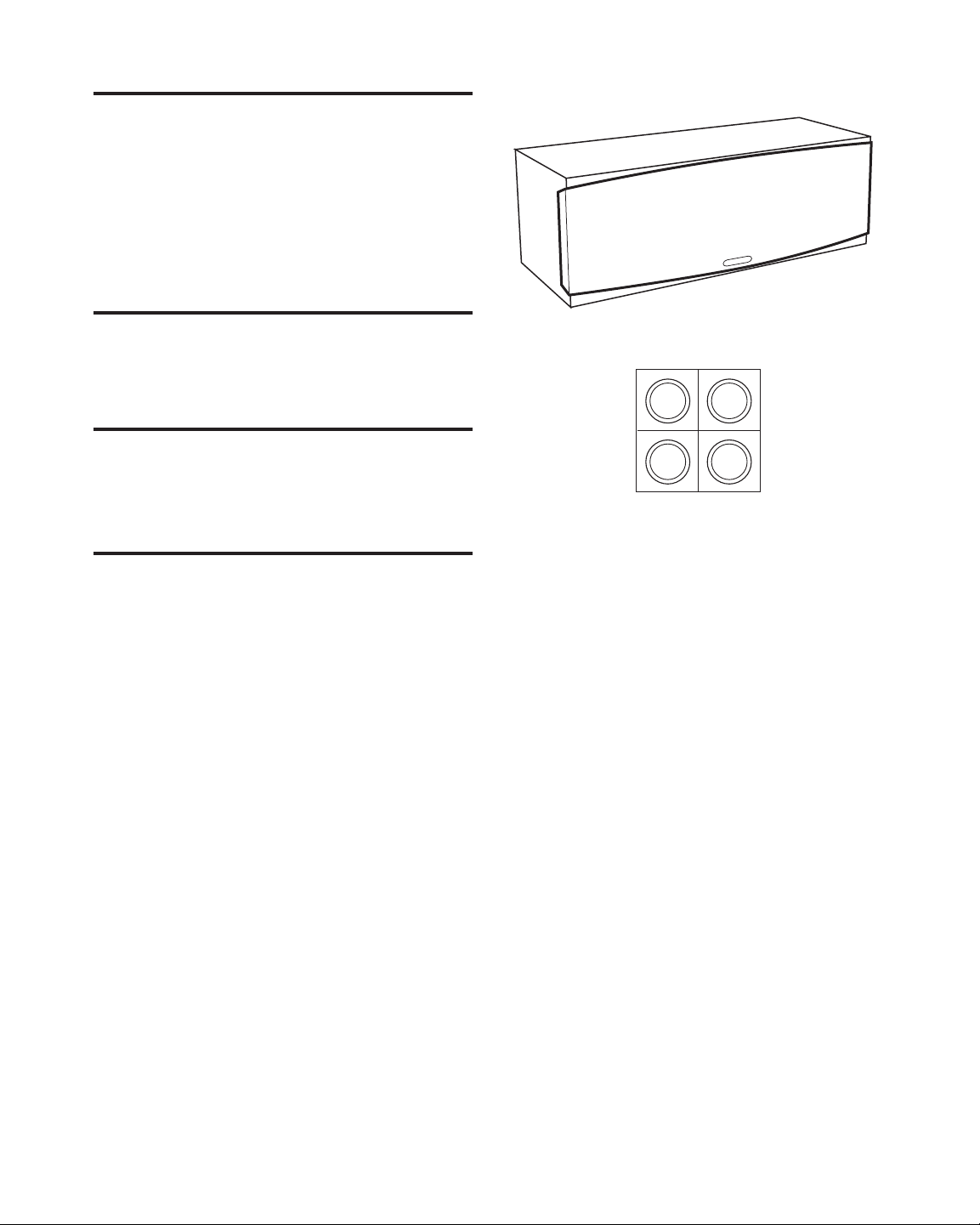
CONTENTS
1. One Speaker
2. Four rubber feet
INSPECTING FOR DAMAGE
Examine each part carefully for shipping damage. If
there is any, do not install or use the speaker. Return
the speaker to the store or merchant where you made
the purchase or call Cambridge SoundWorks at
1-800 FOR-HIFI (1-800-367-4434) for assistance.
MC400
Rubber Feet
1.
2.
Page 4
4
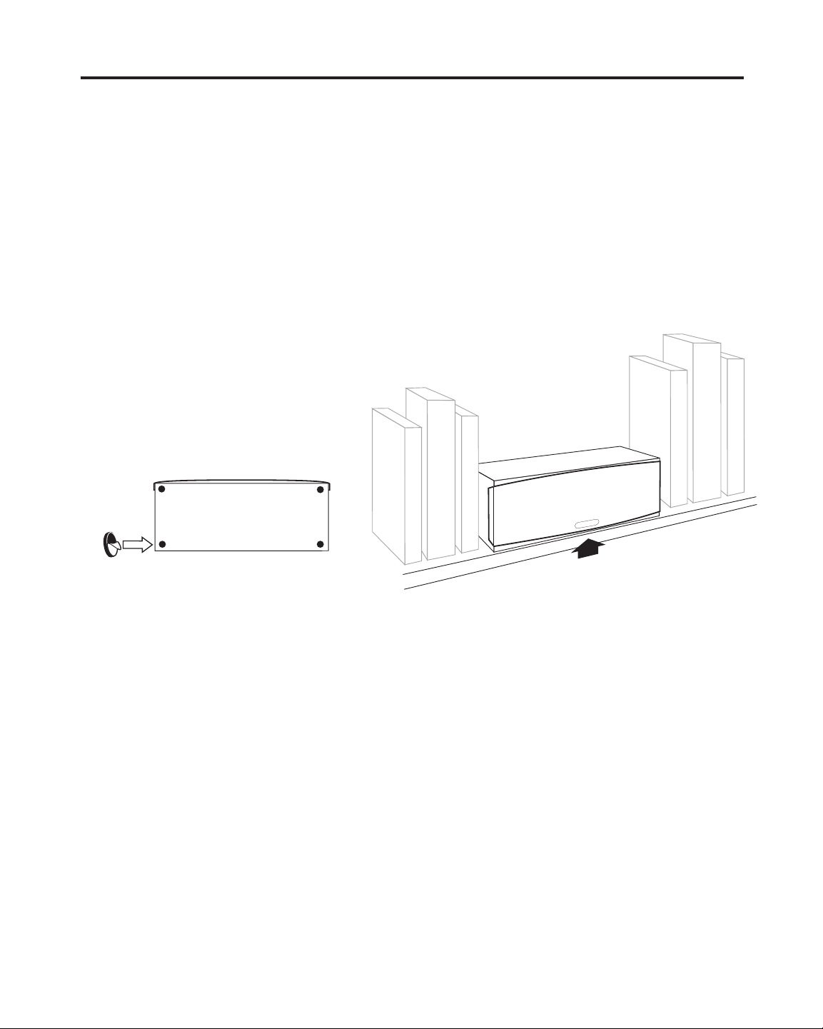
Placing the Speaker on a flat surface:
The MC400 may be positioned vertically or horizontally
on any flat, stable surface. We recommend you apply
the self-adhesive feet to the bottom surface of the
enclosure. The feet protect the finish of the enclosure
and the supporting surface, and improve stability if the
surface is not perfectly flat. Apply the feet close to the
outside corners of the enclosure. The face of the
speaker should be positioned near to or flush with the
edge of the mounting surface for best sound.
SPEAKER PLACEMENT
Near To or Flush with Shelf
Apply Rubber Feet
Page 5

5
Using the MC400 as a Center Channel
The MC400 iutilizes an offset tweeter. The tweeter
should be placed toward the top of the speaker when
the MC400 is used horizontally.
Using the MC400 as Left and Right Speakers
The offset tweeter of the MC400 should be towards
the inside when you are using the MC400s vertically.
The pair should be mirror-imaged.
Logo installation
The logo is shipped uninstalled in order to facilitate
horizontal and vertical placement. To install the logo,
first remove the grille so that you can easily identify
the locations of the logo mounting holes.
Very carefully poke the logo pins through the grille
cloth and seat them in the holes. Be very gentle! The
pins are necessarily small so they do not rip the cloth,
but this makes them easy to break if the pressure is
uneven during installation.
Left Channel Right Channel
Center Channel Orientation
Page 6

6
The following suggestions assume you have some
flexibility regarding where you place your speakers.
Don’t be too concerned if your situation and listening
environment dictate the speakers’ position. The
speakers will still provide convincing, lifelike sound.
• Avoid facing a speaker parallel to a nearby wall
(within 12-14 inches). The reflected sound from the
wall degrades the sound coming directly from
the speaker.
• For stereo systems, position the speakers so they
are approximately at your ear level while sitting or
slightly higher.
Good stereo recordings will “fill” the space between
the speakers with sound – so long as your speakers
aren’t too far apart. Ensure the two speakers form at
least a 20 degree angle with your listening position.
An angle greater than 55 degrees apart sounds more
like two separate speakers, rather than forming a
continuous image of sound between the two speakers.
• For surround systems, position the speakers so they
are approximately the level of the television monitor
or slightly higher.
The Left Front and Right Front channels of a surround
system reproduce sound that corresponds to action
onscreen. Placing the speakers relatively close to the
television monitor (forming no more than a 45 degree
angle with your listening position) helps to “integrate”
the sound with the image onscreen.
POSITIONING YOUR SPEAKERS
SURROUND
SPEAKER
RECOMMENDED DISTANCE
APART FOR STEREO
20 - 55
ANGLE
MAXIMUM RECOMMENDED DISTANCE
APART FOR HOME THEATER
MAIN SPEAKERS
CENTER CHANNEL
LEVEL
WITH
CENTER
SPEAKER
45 ANGLE
EAR LEVEL
OR
SLIGHTLY
HIGHER
POWERED
SUBWOOFER
SURROUND
SPEAKER
Page 7

77
Use at least 18 gauge speaker cable for short runs
(under 15 feet). Use 16 gauge or heavier speaker
cable for longer runs.
1. Determine how long the speaker cable should be
for each speaker. Cut the speaker cable into the
appropriate lengths.
2. Strip 1/2 inch of insulation from the two individual
conductors in the speaker cable. Twist the exposed
strands of bare wire together.
3. Attach any connector plugs (like banana plugs) at
this time.
4. Determine which conductor you will use to connect
the positive terminals of the amplifier and speaker
together. Printing or a ridge on the insulation can
usually distinguish one of the two conductors of
a speaker cable. Sometimes the metal of the
conductors has two different colors.
PREPARE THE SPEAKER WIRE
Strip off 1/2"
Twist Bare Wire
Page 8

CONNECTION DIAGRAMS
Make The Connections:
1. Unscrew the speaker’s red and black connector
knobs to expose the holes in their threaded shafts.
2. Insert the stripped end of one cable’s “indicated”
conductor into the speaker’s red (+) connector.
Hand-tighten the knob to secure the connection.
Make sure no stray strands of wire are exposed.
If you are using cable connector plugs, connect them
according to their instructions
3. Repeat the procedure for the cable’s other
conductor and the speaker’s black (–) connector.
4. Connect the other speaker cable’s conductors to the
other speaker.
5. Connect the opposite end of the speaker cable to the
speaker outputs of your receiver. Remember to
observe channel and polarity (Left Positive, Left
Negative, Right Positive, Right Negative).
8
—
8 Ohms
MC400
Made in China
+
Page 9

99
Using One or More MC400s with
A Powered Subwoofer:
Use a 80 Hz low-pass (high filter) setting on your
powered subwoofer.
Some powered subwoofers provide simple, passive
“high-pass” networks in series with their main speaker
output circuits. Avoid using this type of pass-through
speaker output with a pair of MC400s; drive them with
an amplifier’s normal speaker output. All Cambridge
SoundWorks BassCube
™
subwoofers have full-range,
straight pass-through speaker outputs. You can use
these speaker outputs if it is convenient.
Some Newton Series powered subwoofers have active
100 Hz “high-pass” main speaker outputs for use only
with preamplifier/power amplifier speakers. These
outputs can be used with a pair of MC400s.
Dolby Digital®Decoder Speaker Size Settings:
If your Dolby Digital system combines MC400s and a
powered subwoofer connected to the Dolby Digital
SUB OUT jack, set the decoder's speaker size setting
to SMALL. If there is a crossover frequency feature on
your Dolby Digital decoder, set it as close to 80Hz
as it allows. Set the powered subwoofer crossover to the
highest frequency provided, or to “bypass”. The Dolby
Digital decoder will provide the crossover function.
® Dolby Digital is a registered trademark of Dolby Laboratories Licensing Corporation.
Page 10

1010
MC500:
Dimensions: 7" H x 19 3/4" W x 8" D
Weight: 16.5 pounds each
Impedance: nominal 8 ohms
The M400 can be safely used with any receiver rated
above 30 watts per channel. There is little advantage in
using more power than 150 watts per speaker, but
receivers above this power rating can be used so long
as the reciever is not operated at distorted levels.
Warning About Excessive Amplifier Distortion
Operating a receiver (of any power rating) beyond its
maximum undistorted output level creates distortion –
added high frequency sound not part of the musical
program. Distortion dramatically increases the internal
operating temperature of a speaker and will eventually
cause the speaker’s failure due to burned or melted
internal parts. While Cambridge SoundWorks includes
the most heat-tolerant parts commensurate with good
acoustic design, the speaker’s Limited Warranty against
defects in materials or workmanship does not apply to
parts that fail from long-term operation at very high
temperatures.
Enclosure Cleaning
The speaker enclosures can be cleaned with a soft,
damp cloth.
Brush or vacuum the grille panels if dust accumulates
on them.
SPECIFICATIONS
Page 11

Page 12

P81-1970 Rev A
 Loading...