

Page 1
M-SERIES
DRAW THRU
DIRECT GAS-FIRED
MAKE-UP AIR HEATERS
TECHNICAL MANUAL
mWARNING:
Improper installation, adjustment, alteration, service or maintenance can cause property damage, injury or death. Read the installation, operating, and maintenance instructions thoroughly
before installing or servicing this equipment.
FOR YOUR SAFETY
The use and storage of gasoline or other flammable vapors and liquids in open containers in
the vicinity of this appliance is hazardous.
ASHRAE
FOR YOUR SAFETY
If you smell gas:
1. Open windows.
2. Don’t touch electrical switches.
3. Extinguish any open flame.
4. Immediately call your gas supplier.
Made in the USA
ASHRAE
90.1
COMPLIANT
COMPLIANT
®
®
M-TM1-0915
M110-M115 (3HP) REV. G
M115 (5HP) REV. H
M118-M136 REV. C
M140 REV. A
Page 2

LIMITED WARRANTY
Cambridge Engineering, Inc. (“Manufacturer”) warrants its products (“the Products”) to be free from
defects in material and workmanship. Manufacturer’s M-Series Products shall be warranted for a period of
twenty-four (24) months from the date of shipment, except that burner assemblies are warranted for
five (5) years from date of shipment.
Buyer’s sole and exclusive remedy for any nonconformity with this warranty shall be, at Manufacturer’s
option, repair or replacement of nonconforming parts, provided that Buyer shall return to Manufacturer, shipping
prepaid, said nonconforming part(s) bearing a durable tag indicating the Serial Number of the Product
from which the part was taken. In addition, Manufacturer may opt not to repair or replace nonconforming
Product or part(s), but instead may refund to Buyer the price thereof, in lieu of repair or replacement. In no
event shall Manufacturer be liable for more than a refund of the purchase price or replacement value of the
Product or part(s), whichever is less. This Warranty does not apply to field labor charges.
This Warranty does not apply and shall be void as to any Products that are misused or misapplied, that are
installed, operated or maintained not in conformity with Manufacturer’s design, specifications, instructions, or Technical Manual, or are installed, operated or maintained in violation of any applicable national
or local codes or industry standards.
Manufacturer does not warrant Products if they are abused, improperly operated or maintained, subjected
to abnormal wear and tear, damaged due to improper gas or electric service, damaged in transit, or that
have been repaired or modified by others without Manufacturer’s written authorization.
Buyer shall have no right to enforce this Warranty unless it has complied with all of its obligations under
the contract for purchase/lease of the Products, including without limitation being current on all payment
terms.
THIS LIMITED WARRANTY IS MANUFACTURER’S ONLY WARRANTY WITH RESPECT
TO THE PRODUCTS, AND IT IS IN LIEU OF AND SUPERSEDES ANY AND ALL OTHER
WARRANTIES OF ANY KIND WHATSOEVER, WHETHER WRITTEN, ORAL OR IMPLIED,
INCLUDING WITHOUT LIMITATION ANY IMPLIED WARRANTIES OF MERCHANTABILITY OR
FITNESS FOR A PARTICULAR PURPOSE. THE REMEDIES AFFORDED BUYER BY THIS WARRANTY
ARE THE ONLY REMEDIES AFFORDED BUYER FOR ANY NONCONFORMITY WITH THIS
WARRANTY OR FOR ANY DEFECT IN PRODUCTS, SERVICES, OR REPRESENTATIONS
PROVIDED BY MANUFACTURER IN CONNECTION WITH SUCH PRODUCTS. IN NO EVENT
SHALL MANUFACTURER BEAR ANY LIABILITY FOR INCIDENTAL OR CONSEQUENTIAL
DAMAGES OF ANY KIND WHATSOEVER, INCLUDING WITHOUT LIMITATION PERSONAL
INJURY (INCLUDING DEATH), PROPERTY DAMAGE, LOST PROFITS OR OTHER ECONOMIC
LOSS.
Buyer acknowledges that the foregoing warranty, limitations, and exclusions are a reasonable allocation
of commercial risks by and among sophisticated business entities and are not subject to dispute as to their
commercial reasonableness, fairness or ability to satisfy the essential purposes of the parties’ transaction.
Page 3

M-SERIES
TECHNICAL MANUAL
Contents
Hazard Summary .............................................................................................................. 2
Typical System Overview
Accessory Identication .................................................................................................. 4
Heater / Accessory Weights ............................................................................................5
Heater Operation ............................................................................................................. 6
Heater Conguration
Installation Instructions
Uncrating Instructions
Mounting Location
Horizontal Mount - Mounting Curb ................................................................................ 8
Horizontal Mount - Roof Top Conguration .................................................................. 9
Horizontal Mount - Outdoor Pad Mount Conguration ...............................................13
Horizontal Mount - Thru Wall Conguration ...............................................................16
Vertical Mount - Outdoor Conguration ....................................................................... 19
Vertical Mount - Indoor Conguration .........................................................................23
Gas Piping ..................................................................................................................... 26
Electrical .......................................................................................................................27
Start-Up Instructions ....................................................................................................... 28
Operating Instructions ..................................................................................................... 35
Operating Sequence ......................................................................................................35
Electronic Thermostat ................................................................................................... 36
TSS Controller ..............................................................................................................38
Maintenance Instructions ................................................................................................ 47
Reference ........................................................................................................................ 48
Heater Roof and Wall Openings ...................................................................................48
Heater Discharge Dimensions .......................................................................................48
Gas Train Drawings ......................................................................................................49
Electrical Control Enclosure Isometric Drawing ......................................................... 55
Electrical Wiring Diagrams ........................................................................................... 58
Connection Diagram ..................................................................................................... 64
Gas Control Systems ..................................................................................................... 65
Remote Control Station Components ........................................................................... 65
Individual Heater Component Descriptions .................................................................. 66
Damper Motor Replacement & Adjustment ................................................................. 70
Troubleshooting Guide..................................................................................................73
ANSI/ASHRAE/IESNA Standard 90.1 ..........................................................................79
Maintenance Log ............................................................................................................ 80
................................................................................................. 3
....................................................................................................... 6
..................................................................................................... 7
..........................................................................................................7
Copyright 2015
Cambridge Engineering, Inc.
All Rights Reserved
Cambridge Engineering, Inc.
760 Long Road Crossing Dr.
Chesterfield, MO. 63005
Phone: (636) 532-2233, Fax: (636) 530-6133
www.cambridge-eng.com
Page 4

HAZARD SUMMARY
Hazard Identification
Warnings and Cautions appear at appropriate sections throughout this manual. Read these carefully.
mWARNING: Indicates a potentially hazardous situation which could result in
death or serious injury.
mCAUTION: Indicates a potentially hazardous situation which may result in
minor or moderate injury. It may also be used to alert against
unsafe practices.
CAUTION: Indicates a situation that may result in accidents with equipment or
property damage only.
The following safety precautions apply to the installation, operation, and maintenance of the equipment
described by this technical manual.
mWARNING:
Any unauthorized modification of this equipment
shall void the warranty.
mWARNING:
Only qualified personnel should attempt installation, service, and repair of this equipment. Use
extreme caution and observe safety regulations at
all times.
mWARNING:
Recirculation of room air is not permitted.
Adequate building relief shall be provided so as to not
over-pressurize the building when the make-up air heating system is operating at its rated capacity. It should be
noted that this can be accomplished by taking into
account, through standard engineering methods, the
structure’s designed infiltration rate, by providing properly sized relief openings, by interlocking a powered
exhaust system, or by a combination of these methods.
when the heater is providing the make-up air to a boiler
room), the heater is to be interlocked to open inlet air
dampers or other such devices.
If the heater is installed such that an inlet duct is utilized, the duct system must be purged with at least four
air changes prior to an ignition attempt.
IMPORTANT
Installation in Aircraft Hangars
Refer to the Standard for Aircraft Hangars, ANSI/
NFPA 409, for specific information on the installation
requirements for these heaters in airplane hangars.
IMPORTANT
Installation in Parking Garages
Refer to the Standard for Parking Structures, ANSI/
NFPA 88A, or the Standard for Repair Garages, ANSI/
NFPA 88B, for specific information on the installation
requirements for these heaters in public garages.
If in doubt regarding installation or application,
contact Cambridge Engineering Customer Service
Group at 800-473-4569 during the hours of 8:00 a.m.
to 5:00 p.m. Central Time, Monday through Friday.
If the failure or malfunction of this heater creates a hazard to other fuel burning equipment in the building (e.g.
Cambridge Engineering, Inc. 2 M-Series Technical Manual
Page 5

TYPICAL SYSTEM OVERVIEW
CONTROL SYSTEMS:
MAXITROL SERIES 14
The Maxitrol Series 14 electronic discharge temperature
control system maintains a constant discharge temperature. The standard control permits manual adjustment
of discharge temperature (55° to 90°F) from inside the
heater control enclosure. As an option, a Remote Heat
Adjust control with override capability to 130°F can be
provided to allow manual adjustment of discharge temperature (55° to 130°F) from either inside the heater con-
trol enclosure or in the Remote Control Station.
MAXITROL SERIES 14 WITH SPACE
THERMOSTAT
The Maxitrol Series 14 modulation controls function as
described above using the optional Remote Heat Adjust
control in conjunction with an electronic space thermostat switch contact to increase discharge temperature.
The discharge temperature will increase to a preset rise
(0°F to 40°F) above the set point on the Remote Heat
Adjust control face based on the setting of the override
temperature dial, which is visible from the top of the
control.
MAXITROL SERIES 44
The Maxitrol Series 44 modulation controls maintain
a constant space temperature by increasing or decreasing the discharge temperature. The Space Temperature
Selector is set to maintain the space temperature of the
heated space by controlling the heater output between
the MIN and MAX setting on the amplifier. The MIN
dial setting determines the minimum discharge temperature the heater will deliver (40°F to 80°F). The MAX dial
setting determines the maximum discharge temperature
the heater will deliver (80°F to 140°F).
MAXITROL SERIES 44 / TAMPER PROOF
The Maxitrol Series 44 / Tamper Proof temperature
control system is similar to the Maxitrol Series 44 controls above except the adjustable Space Temperature
Selector control is replaced by two other controls. The
adjustable portion of the temperature selector is typically
mounted in the Remote Control Station to prevent unwanted
tampering of the temperature setting and the non-adjustable
space sensor is mounted in the space being heated.
M-Series Technical Manual 3 Cambridge Engineering, Inc.
Page 6
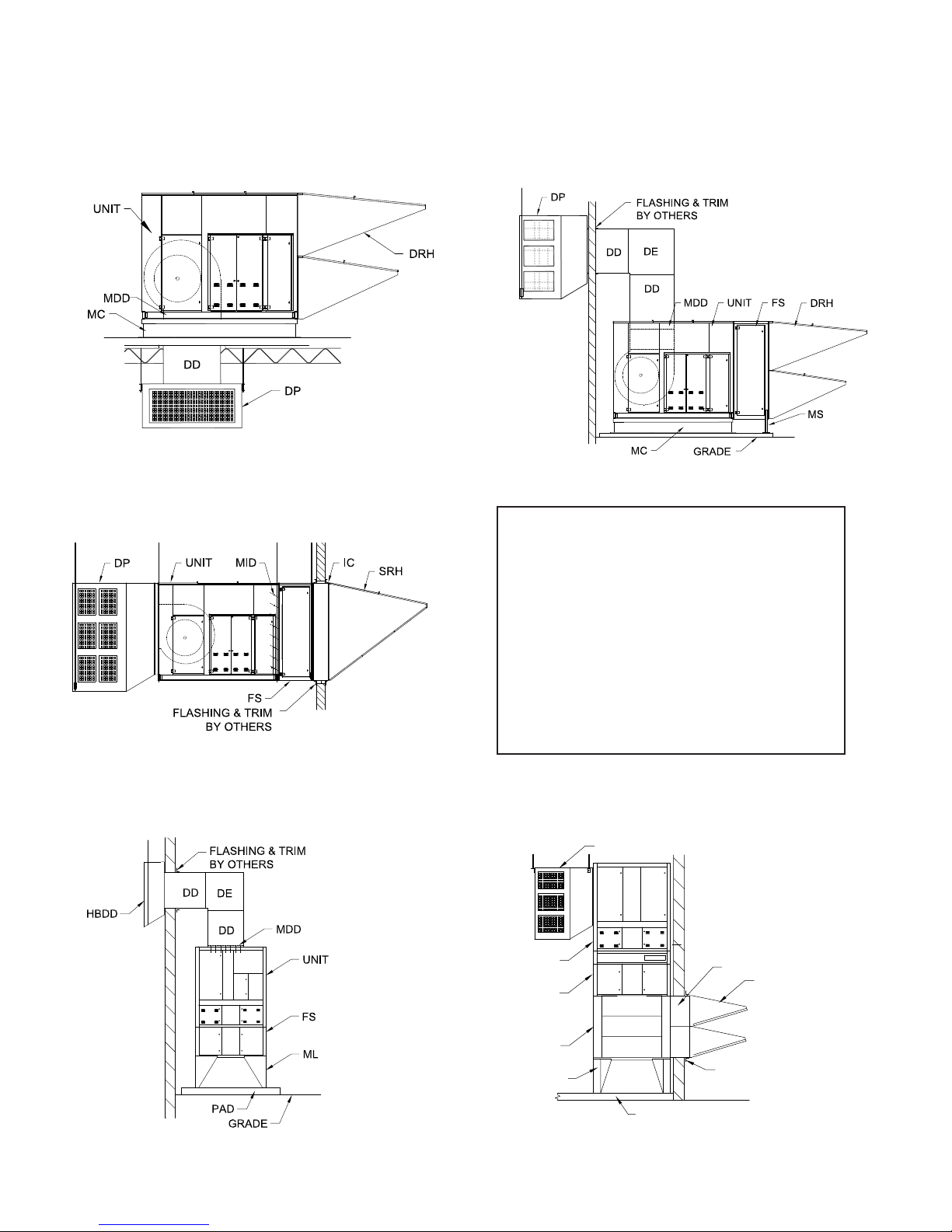
TYPICAL SYSTEM OVERVIEW
FLOOR
ACCESSORY IDENTIFICATION
Horizontal Mount
Roof Top Configuration
Horizontal Mount
Thru Wall Configuration
(Not applicable to M140)
Horizontal Mount
Outdoor Pad Mount Configuration
Component Identification
DD Discharge Duct
DE Discharge Elbow
DP Discharge Plenum
DRH Dual Rainhood w/ Inlet Screen & Filter Rack
FS Filter Section V-Bank
FSID V-Bank Filter Section/Inlet Damper Combo
HBDD Horizontal Blast Discharge Diffuser
IC Inlet Collar
IE Inlet Elbow
MC Mounting Curb
MDD Motorized Discharge Damper
MID Motorized Inlet Damper
ML Mounting Legs
SRH Single Rainhood w/ Inlet Screen
Vertical Mount
Outdoor Configuration
Cambridge Engineering, Inc. 4 M-Series Technical Manual
UNIT
FSID
Vertical Mount
Indoor Configuration
DP
IE
ML
IC
DRH
FLASHING & TRIM
BY OTHERS
Page 7

HEATER / ACCESSORY WEIGHTS
Horizontal Mount (Weights Shown In Pounds)
Model M110 M112 M115
Base Heater
Rain Hood - Single
Rain Hood - Dual, Upper
Rain Hood - Dual, Lower
Filters for Rain Hood
Inlet Screen
Inlet Collar
Inlet Damper (internal)
V-Bank Filter Section
Discharge Duct - 20"
425 440 550 1125 1395 2045 2475 2845 5345*
45 45 70 135 175 275 325 375 N/A
N/A N/A N/A 95 145 240 270 325 480
N/A N/A N/A 75 105 170 205 280 410
10 10 15 20 30 45 60 80 90
5 5 10 10 15 25 35 40 45
40 40 50 85 110 170 200 230 335
25 25 35 55 65 125 155 210 290
70 70 100 215 235 285 400 500
M118 M120 M125 M130 M136 M140
**
Discharge Duct - 50"
Discharge Duct - 72"
Discharge Damper (internal)
Discharge Plenum 4-way
Discharge Plenum 3-way
Discharge Splash Pan
Curb 14"
Curb 24"
60 70 80 90 120 140 160 180 200
70 85 95 125 150 180 220 250 280
N/A N/A N/A 30 30 35 45 55 75
100 150 200 250 300 400 470 930 1480
80 130 175 220 260 360 430 500 795
40 40 40 60 60 60 80 80 80
60 70 80 100 120 180 210 230 270
100 120 140 170 200 270 310 340 445
*Due to shipping constraints the M140 consists of a of blower module (3625 lbs.) and burner module (1720 lbs.)
**Consult Factory
Vertical Mount (Weights Shown In Pounds)
Model
Base Heater
Rain Hood - Single
Rain Hood - Dual, Upper
Rain Hood - Dual, Lower
Filters for Rain Hood
Inlet Collar
Inlet Elbow
Inlet Damper
V-Bank Filter Section
Filter Section/Inlet Damper Combo
Discharge Duct - 20"
Discharge Duct - 50"
Discharge Duct - 72"
Discharge Damper (internal)
Discharge Elbow
Discharge Plenum 3-way w/enclosure
Discharge Diffuser
Mounting Legs 3-foot, set of 4
Mounting Legs 5-foot, set of 4
M118 M120 M125 M130 M136
1800 2300 2900 3200 3600
105 165 285 395 485
80 120 210 290 345
55 90 150 210 275
20 30 45 60 80
80 110 170 200 230
450 500 780 1040 1175
305 345 400 475 490
280 380 420 555 715
470 600 670 860 920
90 120 140 160 180
125 150 180 220 250
35 35 40 60 75
95 120 170 230 340
280 320 420 510 580
210 230 280 310 350
250 250 250 250 250
400 400 400 400 400
M-Series Technical Manual 5 Cambridge Engineering, Inc.
Page 8
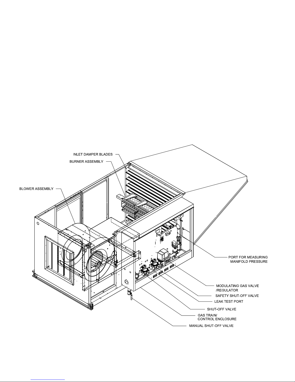
TYPICAL SYSTEM OVERVIEW
HEATER OPERATION
Cambridge M-Series Draw-Thru heaters provide
fresh air ventilation to a facility, provide tempered air
to replace the air that is mechanically exhausted, or
address cold drafts from natural infiltration. Heater
operation is typically electrically interlocked with
mechanical exhaust fans, manually operated switches,
HEATER CONFIGURATION
programmable timers, or other process control systems. The discharge temperature of heaters with fixed
discharge temperature controls is typically set 10°F to
20°F above the desired space temperature. The entering air thermostat acts as an economizer by deactivating burner operation during mild weather.
Cambridge Engineering, Inc. 6 M-Series Technical Manual
Page 9

INSTALLATION INSTRUCTIONS
UNCRATING INSTRUCTIONS
1. Verify the number of items on the Bill of Lading
versus the number of items received.
IMPORTANT
Field constructed intake accessories should be designed to minimize the entry of snow
and rain.
2. Check for shipping damage. If damage is found,
immediately file a claim with carrier before
proceeding further.
3. Check items received to make sure they agree with
ordering information including verification of data
on the make-up air heater nameplate.
IMPORTANT
Do not discard any components or accessories.
MOUNTING LOCATION
Verify feasibility of the installation location selected
with respect to accessibility to the heater for service
and maintenance functions. Ensure the positioning of
the heater does not inhibit fork truck operation, storage rack access, or other operations within the facility.
Ensure the heater inlet and outlet are not blocked or
severely restricted, such that it would affect the rated
airflow through the heater or affect the desired air distribution pattern of the heater. If upon review of the
proposed installation, a problem is discovered which
may be considered detrimental to the performance of
the heater, or restricts its serviceability, or deviates from
the instructions or drawings which may be provided, it
is the responsibility of the installer to communicate that
information to the person or persons responsible for providing the installation instructions or drawings prior to
proceeding with the installation.
IMPORTANT
Minimum clearance from the face of the electrical control enclosure to surrounding grounded surfaces for
service activities is 42". Adequate clearance for burner
removal is also required, which is based on 42" or
the length of the burner + 12", whichever is greater.
Access for service functions is also required on the opposite side of the make-up air heater from the control
enclosure for a distance of 24".
mWARNING:
Where the mounting height of the heater is
required to be above 15 feet, work platforms or
service lifts should be provided for accessibility to the equipment for service and maintenance
activities.
M-Series Technical Manual 7 Cambridge Engineering, Inc.
Page 10
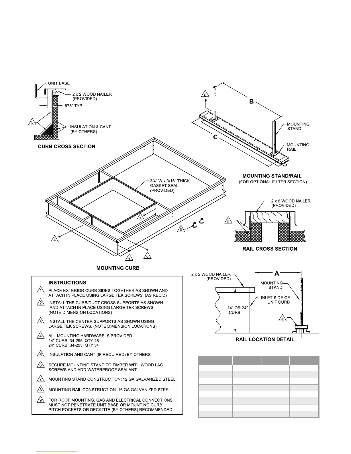
INSTALLATION INSTRUCTIONS
HORIZONTAL MOUNT - MOUNTING CURB
M110 - M136
(Shown for Roof Top Configuration - Downblast Application)
Cambridge Engineering, Inc. 8 M-Series Technical Manual
Model A B C
M110
M112
M115
M118
M120
M125
M130
M136
32.38" 27.12" 48"
32.38" 27.12" 48"
32.38" 40.31" 60"
32.38" 44.10" 60"
32.38" 50.26" 72"
37.88" 63.12" 84"
37.63" 84.81" 96"
37.88" 84.81" 96"
Page 11

INSTALLATION INSTRUCTIONS
HORIZONTAL MOUNT - ROOF TOP CONFIGURATION
mWARNING:
Due to the size and weight of this equipment, it is
recommended that the heater support structure be
reviewed and approved by a qualified structural engineer and the roof manufacturer before installing this
equipment.
IMPORTANT
Before proceeding with the installation, verify the feasibility of the location selected with respect to accessibility to the equipment for service and maintenance
functions.
IMPORTANT
To minimize snow and rain ingestion, position the heater inlet opposite the prevailing wind.
mCAUTION:
To prevent contaminated air from being drawn into
the heater, install the heater’s inlet at least 10 feet
from any building exhaust, process exhaust, sewer
stacks, or other sources that would allow contaminants to be drawn into the heater. Consult local
codes for applicable building code provisions for
ventilation air.
IMPORTANT
For model M140 heaters, refer to the “Field Assembly
Instructions” worksheets included with this manual for
detailed heater assembly directions.
IMPORTANT
The roof curb or support structure should be installed such that the heater will sit level. Cambridge
Engineering recommends mounting the heater 24" off
the roof surface in areas where snow accumulation
could impact heater operation.
3. Lower the discharge duct through the roof opening.
4. Install the roof curb gasket.
5. Use a crane or comparable lifting device to raise
and position the equipment. Block the heater where
necessary. Use a spreader bar to prevent damage and
connect slings to the lifting eyes.
6. Caulk all joints of the heater’s accessories installed
in the field. Use a clear or gray latex based polyurethane caulking to prevent water leaks.
7. Seal all roof penetrations to prevent roof leaks.
8. Install the discharge plenum, where used, by screwing the plenum to the discharge duct. Install 4 hanging rods from the ceiling supports to the plenum’s
support brackets.
1. Prepare the roof for installation. (See pages 10-12
for roof opening dimensions for your specific
heater.) The gas and electrical connections must not
penetrate the unit base or mounting curb. Cambridge
Engineering recommends using pitch pockets or
decktite to seal the penetrations.
IMPORTANT
Accurate measurements are critical and will affect installation process.
2. Assemble and secure the roof curb to the support
structure per the recommendations of the structural
engineer and roof manufacturer.
M-Series Technical Manual 9 Cambridge Engineering, Inc.
Page 12

TYPICAL INSTALLATION
HORIZONTAL MOUNT - ROOF TOP CONFIGURATION
M110 - M115
Roof Opening
Model W L
M110
M112
M115
19.25" 19.25"
20.75" 20.75"
23.5" 23.75"
Cambridge Engineering, Inc. 10 M-Series Technical Manual
Typical Curb and
Discharge Duct
Typical Curb and
Discharge Duct
Page 13
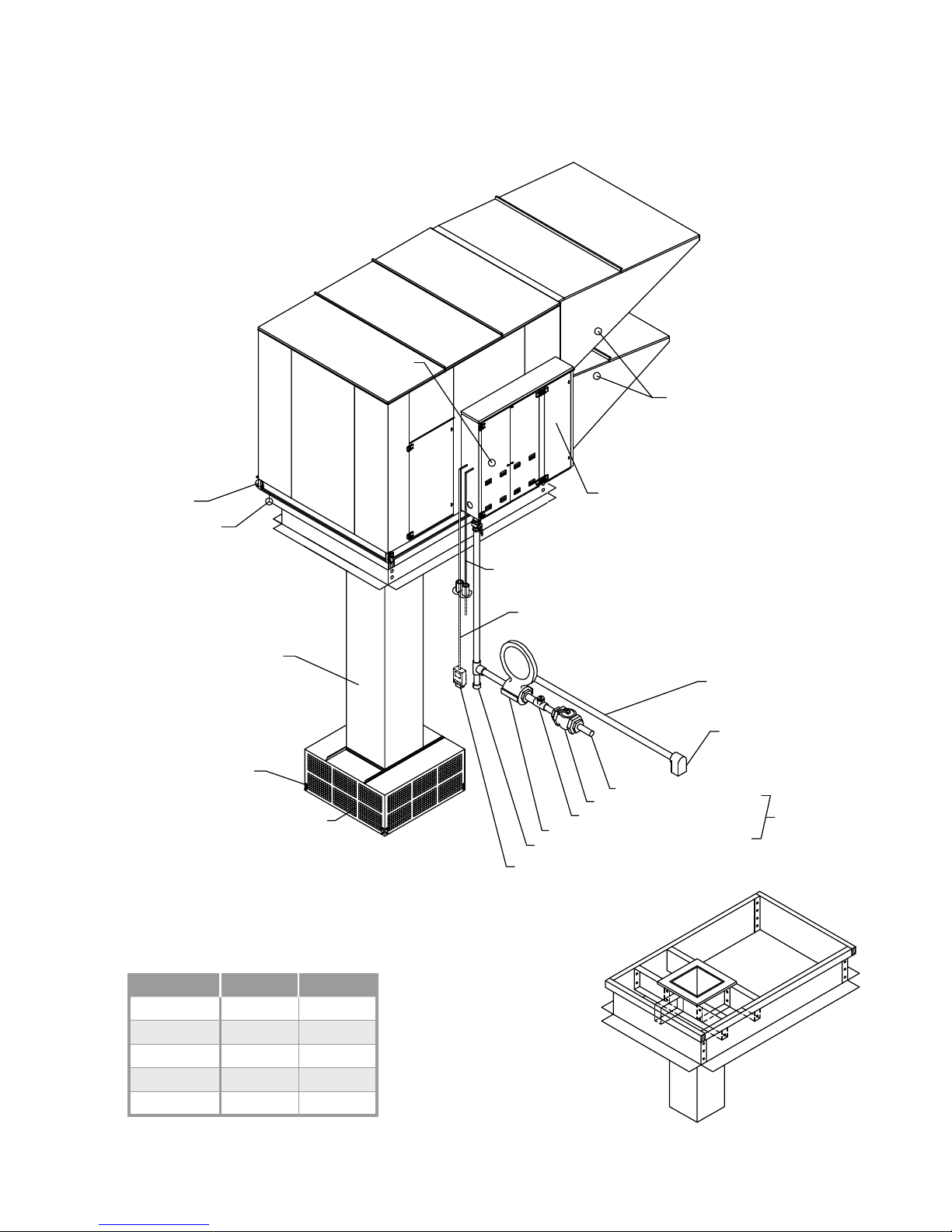
TYPICAL INSTALLATION
HORIZONTAL MOUNT - ROOF TOP CONFIGURATION
M118 - M136
GAS CONTROL
ENCLOSURE
RAINHOOD
LIFTING EYES
MOUNTING
CURB
DISCHARGE
HANGING
BRACKET
DUCT
DISCHARGE
PLENUM
INCOMING POWER
CONTROL WIRING CONDUIT
7-9 WIRES REQ'D
(BY OTHERS)
HIGH PRESSURE SUPPLY TAP
HIGH PRESSURE REGULATOR (HPR)
SEDIMENT TRAP (BY OTHERS)
RCS
ELECTRICAL CONTROL ENCLOSURE
VENT PIPE
(BY OTHERS)
VENT w/ SCREEN
(LOCATE MIN. 10 FT FROM INTAKE)
INLET GAS PIPE
HIGH PRESSURE SHUT-OFF VALVE
HPR
(OPTION)
Roof Opening
Model W L
M118
M120
M125
M130
M136
26.5" 26.5"
30.5" 30.5"
36" 36"
42" 42"
48" 48"
M-Series Technical Manual 11 Cambridge Engineering, Inc.
Typical Curb and
Discharge Duct
Page 14
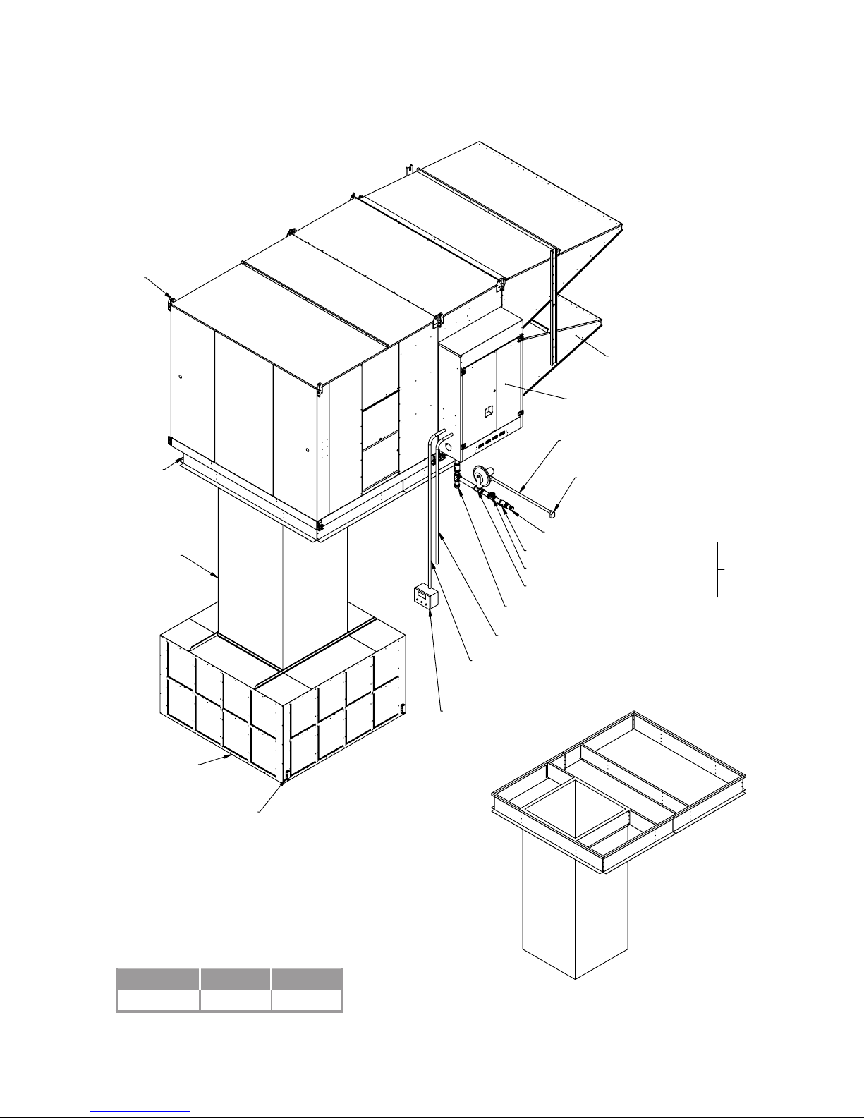
TYPICAL ROOF TOP INSTALLATION
TYPICAL INSTALLATION
HORIZONTAL MOUNT - ROOF TOP CONFIGURATION
M140
Lift Eyes
Rainhoods
Gas Control Enclosure
Vent Pipe (By Others)
Mounting Curb
Discharge Duct
Discharge Plenum
Hanger Bracket
Incoming Power
Control Wiring Conduit
7-9 Wires Req'd
(By Others)
RCS
Typical Curb and
Typical Curb and
Discharge Duct
Discharge Duct
Vent w/ Screen
(Locate Min 10 Ft from Intake)
Inlet Gas Pipe
High Pressure Shut-off Valve
High Pressure Supply Tap
High Pressure Regulator (HPR)
Sediment Trap (By Others)
HPR
(Option )
Roof Opening
Model W L
M140
55" 55"
Cambridge Engineering, Inc. 12 M-Series Technical Manual
Page 15

INSTALLATION INSTRUCTIONS
HORIZONTAL MOUNT - OUTDOOR PAD MOUNT CONFIGURATION
IMPORTANT
mWARNING:
Due to the size and weight of this equipment, it
is recommended the heater support structure be
reviewed and approved by a qualified structural engineer before installing this equipment.
IMPORTANT
Before proceeding with the installation, verify the feasibility of the location selected for accessibility to the
equipment for service and maintenance functions.
IMPORTANT
To minimize snow and rain ingestion, position the
heater inlet opposite the prevailing wind.
mCAUTION:
To prevent contaminated air from being drawn into
the heater, install the heater’s inlet at least 10 feet
from any building exhaust, process exhaust, sewer
stacks, or other sources that would allow contaminants to be drawn into the heater. Consult local
codes for applicable building code provisions for
ventilation air.
Cambridge Engineering recommends mounting the
heater a minimum of 24" off the mounting surface in
areas where snow accumulation could impact heater
operation.
4. Caulk all joints of the heater’s accessories installed
in the field. Use a clear or gray latex based polyurethane caulking to prevent water leaks.
5. Install the discharge duct through the wall opening.
6. Install fiberglass insulation in the gaps between the
wall opening and discharge duct. Apply enough
insulation material to accommodate the full thickness of the wall.
7. Install finish trim pieces (by others) to the top, sides
and bottom of the discharge duct on both the inside
and outside wall surfaces.
8. Apply a bead of latex based polyurethane caulk that
best matches the color of the exterior wall surface
of the facility and/or the color of the heater accessories
at the joint between the top discharge duct and outside
wall surface. Make certain this is a continuous bead and
that it runs the entire width of the duct. Caulk all other
exposed joints.
IMPORTANT
For model M140 heaters, refer to the “Field Assembly
Instructions” worksheets included with this manual for
detailed heater assembly directions.
1. Prepare the wall for installation. (See pages 14-15
for wall opening dimensions for your specific
heater.)
IMPORTANT
Accurate measurements are critical and will affect installation process.
2. Assemble and secure the support structure per the
structural engineer’s recommendations.
IMPORTANT
The support structure should be installed such that the
heater will sit level.
3. Use a crane or comparable lifting device to raise and
position the equipment. Block the heater where
necessary. Use a spreader bar to prevent damage and
connect slings to the lifting brackets.
9. Install the discharge plenum, where used, by screwing the plenum to the discharge duct. Install hanging
rods from the ceiling supports to the plenum’s support brackets.
M-Series Technical Manual 13 Cambridge Engineering, Inc.
Page 16
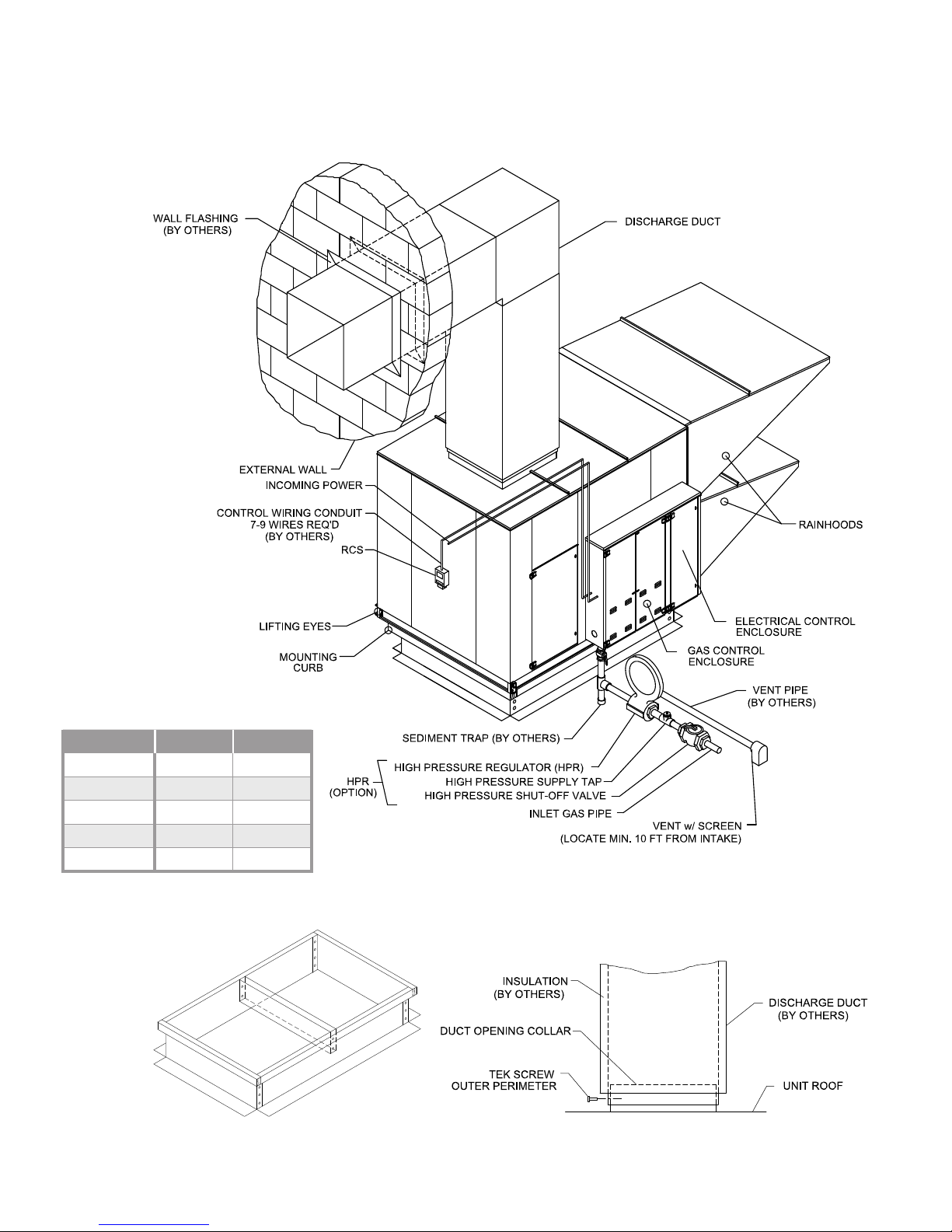
TYPICAL INSTALLATION
HORIZONTAL MOUNT - OUTDOOR PAD MOUNT CONFIGURATION
M118 - M136
Wall Opening
Model W L
M118
M120
M125
M130
M136
25.5" 25.5"
29.5" 29.5"
35" 35"
41" 41"
47" 47"
Typical Curb
Typical Duct Interface
Cambridge Engineering, Inc. 14 M-Series Technical Manual
Page 17
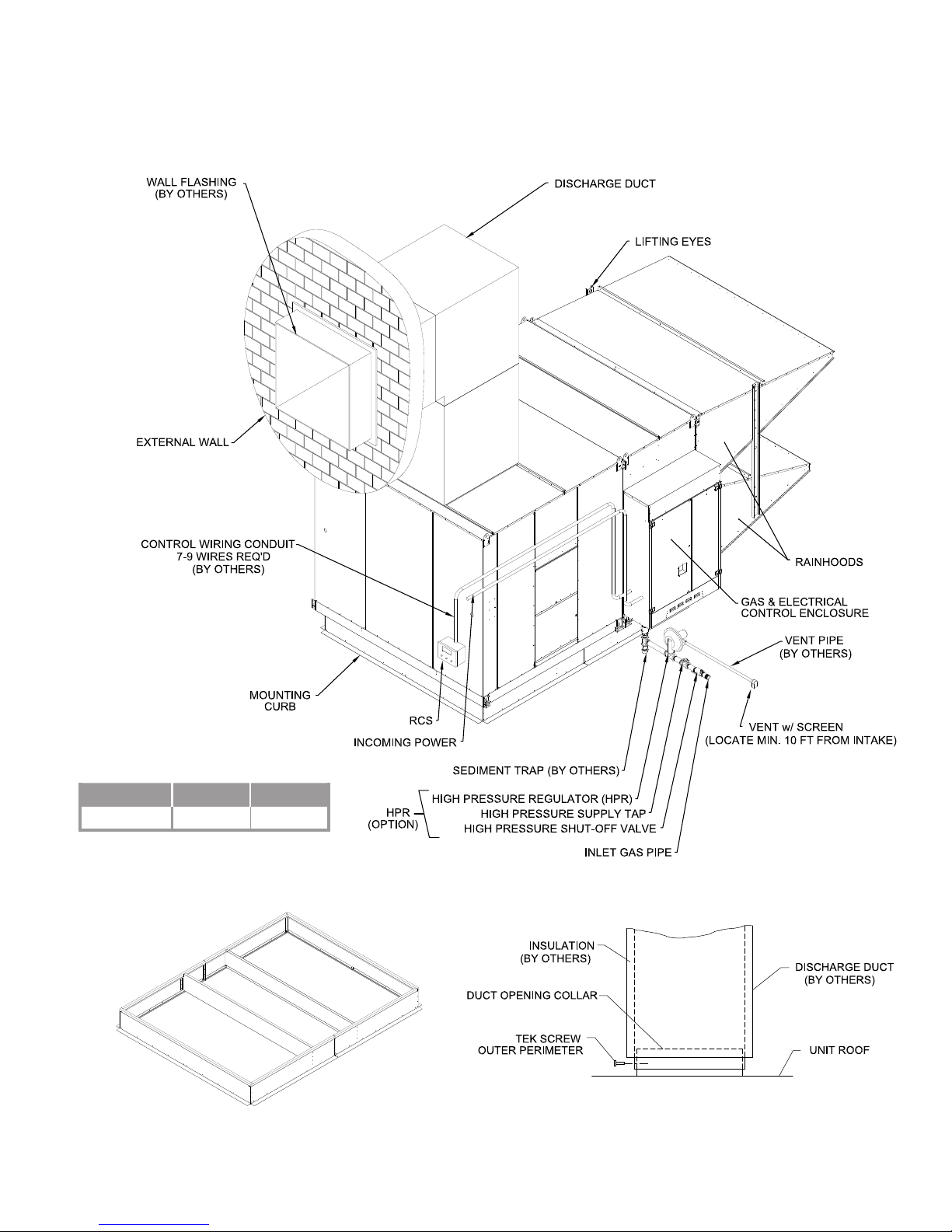
TYPICAL INSTALLATION
HORIZONTAL MOUNT - OUTDOOR PAD MOUNT CONFIGURATION
M140
Wall Opening
Model W L
M140
54" 54"
TYPICAL CURB
M-Series Technical Manual 15 Cambridge Engineering, Inc.
Typical Duct Interface
Page 18

INSTALLATION INSTRUCTIONS
HORIZONTAL MOUNT - THRU WALL CONFIGURATION
mWARNING:
Due to the size and weight of this equipment, it is
recommended that the heater support structure be
reviewed and approved by a qualified structural engineer before installing this equipment.
IMPORTANT
Before proceeding with the installation, verify the feasibility of the location selected with respect to accessibility to the equipment for service and maintenance
functions.
IMPORTANT
To minimize snow and rain ingestion, position the heater inlet opposite the prevailing wind.
mCAUTION:
To prevent contaminated air from being drawn into
the heater, install the heater’s inlet at least 10 feet
from any building exhaust, process exhaust, sewer
stacks, or other sources that would allow contaminants to be drawn into the heater. Consult local
codes for applicable building code provisions for
ventilation air.
4. Apply washers and double lock nuts to secure equipment on hanging rods. Note: The discharge end of
the heater should be raised slightly (1/8
to allow ingested moisture to drain from the heater.
5. Apply shims at the bottom of the rainhood to take up
slack in the opening, leaving a small joint between
the top of the heater and the wall.
6. Install fiberglass insulation in the gaps between the
wall opening and the inlet collar. Apply enough
material to accommodate the full thickness of the
wall.
7. Install finish trim pieces (by others) to the top, sides
and bottom of the inlet collar on both the inside and
the outside wall surfaces.
8. Apply a bead of latex based polyurethane caulk that
best matches the color of the exterior wall surface
of the facility and/or the color of the heater accessories
at the joint between the top inlet collar and outside wall
surface. Make certain this is a continuous bead and
that it runs the entire width of the collar. Caulk all other
exposed joints.
" above level)
1. Prepare the wall for installation. (See pages 17-18 for
wall opening dimensions for your specific heater.)
IMPORTANT
Accurate measurements are critical and will affect the
installation process.
2. Install heater support rods per the structural engineer’s recommendations.
3. Use a crane or comparable lifting device to raise and
position equipment. Block the heater where necessary. Use a spreader bar to prevent damage and connect slings to the lifting brackets.
IMPORTANT
Cambridge Engineering recommends mounting the
heater’s rainhood a minimum of 24" off the ground or
other surfaces.
9. Install the discharge plenum, where used, by screwing the plenum to the heater or to the discharge duct,
as applicable. Install hanging rods from the ceiling
supports to the plenum’s support brackets.
Cambridge Engineering, Inc. 16 M-Series Technical Manual
Page 19
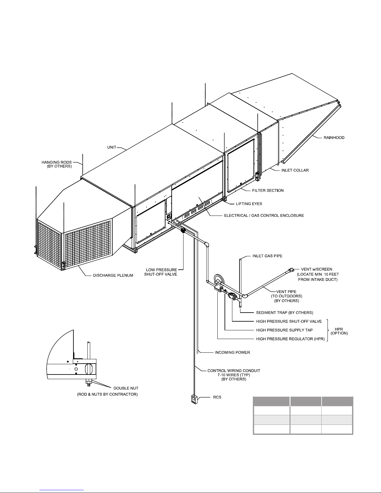
TYPICAL INSTALLATION
HORIZONTAL MOUNT - THRU WALL CONFIGURATION
M110 - M115
M-Series Technical Manual 17 Cambridge Engineering, Inc.
Wall Opening
Model W H
M110
M112
M115
32" 35.25"
32" 35.25"
46" 35.25"
Page 20
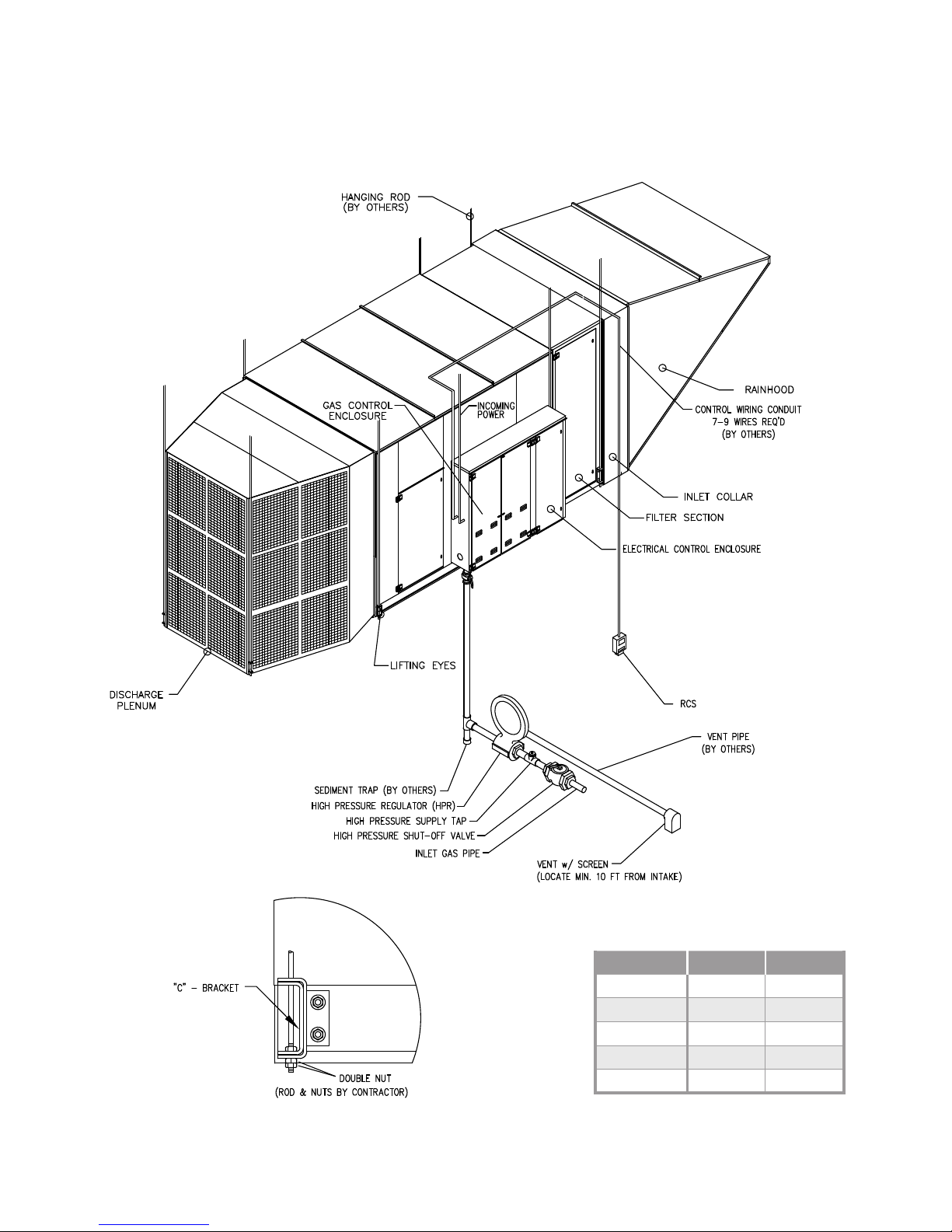
TYPICAL INSTALLATION
HORIZONTAL MOUNT - THRU WALL CONFIGURATION
M118 - M136
Cambridge Engineering, Inc. 18 M-Series Technical Manual
Wall Opening
Model W H
M118
M120
M125
M130
M136
50" 55"
56" 55"
68" 71.75"
89.75" 71.75"
89.75 96.75"
Page 21

INSTALLATION INSTRUCTIONS
VERTICAL MOUNT - OUTDOOR CONFIGURATION
IMPORTANT
Before proceeding with the installation, verify the feasibility of the location selected with respect to accessibility to the equipment for service and maintenance
functions.
IMPORTANT
To prevent contaminated air from being drawn into the
heater, install the heater’s inlet at least 10 feet from
any building exhaust, process exhaust, sewer stacks,
or other sources that would allow contaminants to be
drawn into the heater. Consult local codes for applicable building code provisions for ventilation air.
IMPORTANT
This heater should be mounted on a concrete pad with
a minimum thickness of 4" and with length and width
dimensions that exceed the dimensions of the heater by
at least 5 feet (30" on each side). The pad should be
poured at least two weeks before installation begins to
permit proper curing. The pad should slope slightly
away from the building (approximately 1/4" per foot) to
avoid water collecting under the heater.
1. Prepare the wall for installation. (See pages 21-22
for opening dimensions for your specific heater.)
Accessory Identification drawings (see page 4) to
identify the locations of these sections.
IMPORTANT
Cambridge Engineering recommends mounting the
heater a minimum of 60" off the mounting surface
in areas where snow accumulation could impact the
heater operation.
4. Attach each mounting leg to the inlet accessory (filter section, inlet damper, or filter section/inlet damper combo, as specified) using the 1/2"-13 x 1-1/2"
bolts. The bolts install downward through a clearance hole in the accessory into a threaded insert in
the mounting leg. Install all four legs on the accessory, then set this assembly in its intended position.
If no inlet accessory is specified, install the legs
directly to the heater. Level the assembly by placing
shims under the appropriate legs.
5. Position the heater on the inlet accessory. Secure
the heater using the 1/2"-13 x 1-1/2" bolts. The
bolts install downward through a clearance
hole in the heater into a threaded insert in the inlet
accessory.
6. Attach discharge duct to heater.
IMPORTANT
Accurate measurements are critical and will affect the
installation process.
2. Install the discharge duct through the wall opening.
3. Use a crane or comparable lifting device to raise and
position the equipment. Block the heater where necessary. Use a spreader bar to prevent damage and
connect slings to the lifting eyes.
The Vertical Mount heaters may be shipped in
sections due to shipping constraints. Review the
M-Series Technical Manual 19 Cambridge Engineering, Inc.
7. Caulk all joints of the heater’s accessories installed
in the field. Use a clear or gray latex based polyurethane caulking to prevent water leaks.
8. Install fiberglass insulation in the gaps around the
wall opening and discharge duct. Apply enough
insulation material to accommodate the full thickness
of the wall.
9. Install finish trim pieces (by others) to the top, sides
and bottom of the discharge duct on both the inside
and outside wall surfaces.
Page 22
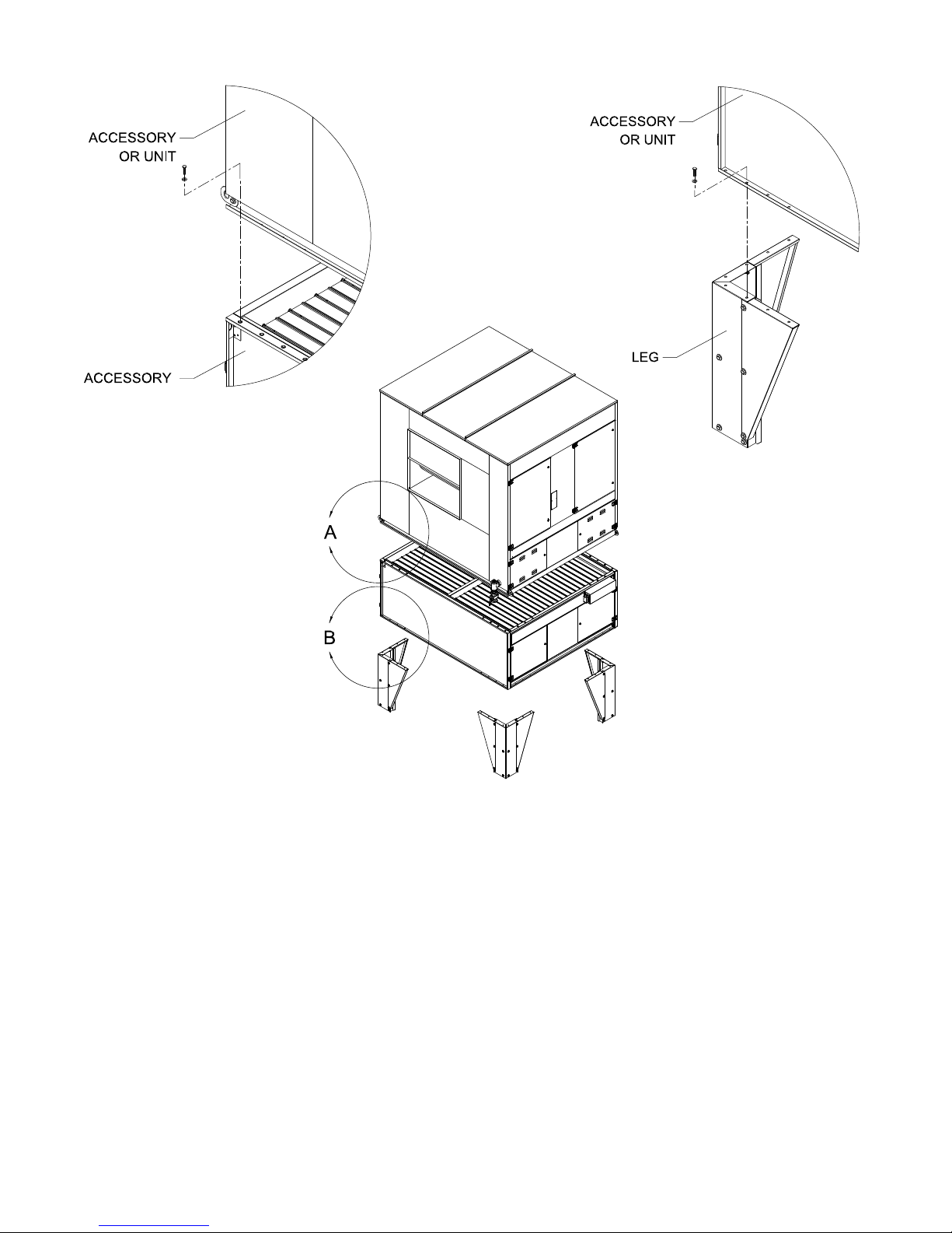
DETAIL A
DETAIL B
10. Apply a bead of latex based polyurethane caulk that
best matches the color of the exterior wall surface
of the facility and/or the color of the heater accessories at the joint between the top discharge duct and
outside wall surface. Make certain this is a continuous bead and that it runs the entire width of the duct.
Caulk all other exposed joints.
Cambridge Engineering, Inc. 20 M-Series Technical Manual
11. Install the discharge plenum by screwing the plenum
to the discharge duct. Install hanging rods from ceiling supports to the plenum’s support brackets.
Page 23

TYPICAL INSTALLATION
HIGH PRESSURE REGULATOR (HPR)
VERTICAL MOUNT - OUTDOOR CONFIGURATION
HORIZONTAL BLAST
M118 - M136
LIFTING
BRACKETS
EXTERNAL WALL
WALL FLASHING
(BY OTHERS)
CONTROL WIRING CONDUIT
7-9 WIRES REQ'D
(BY OTHERS)
Wall Opening
Model W H
M118
M120
M125
M130
M136
RCS
INCOMING
POWER
25.5" 25.5"
29.5" 29.5"
35" 35"
41" 41"
47" 47"
SEDIMENT TRAP
(BY OTHERS)
VENT PIPE
(BY OTHERS)
INLET GAS PIPE
HIGH PRESSURE SHUT-OFF VALVE
HIGH PRESSURE SUPPLY TAP
VENT w/ SCREEN
(LOCATE MIN.
10 FT FROM INTAKE)
HPR
(OPTION)
M-Series Technical Manual 21 Cambridge Engineering, Inc.
Page 24

TYPICAL INSTALLATION
(OPTION)
VERTICAL MOUNT - OUTDOOR CONFIGURATION
UP BLAST
M118 - M136
DISCHARGE DUCT
DISCHARGE ELBOW
W/ TURNING VANES
DISCHARGE DUCT
Model W H
M118
M120
M125
M130
M136
Wall Opening
25.5" 25.5"
29.5" 29.5"
35" 35"
41" 41"
47" 47"
WALL FLASHING
(BY OTHERS)
EXTERNAL WALL
RCS
CONTROL WIRING CONDUIT
7-9 WIRES REQ'D
(BY OTHERS)
INSULATION
DUCT OPENING COLLAR
TEK SCREW
OUTER PERIMETER
INCOMING
POWER
SEDIMENT TRAP
(BY OTHERS)
DISCHARGE DUCT
UNIT ROOF
LIFTING BRACKETS
VENT PIPE
(BY OTHERS)
VENT w/ SCREEN
(LOCATE MIN. 10 FT
FROM INTAKE)
INLET GAS PIPE
HIGH PRESSURE SHUT-OFF VALVE
HIGH PRESSURE SUPPLY TAP
HIGH PRESSURE REGULATOR (HPR)
HPR
Cambridge Engineering, Inc. 22 M-Series Technical Manual
Page 25

INSTALLATION INSTRUCTIONS
VERTICAL MOUNT - INDOOR CONFIGURATION
IMPORTANT
Before proceeding with installation, verify the feasibility of the location selected with respect to accessibility
to the equipment for service and maintenance functions.
IMPORTANT
To prevent contaminated air from being drawn into the
heater, install the heater’s inlet at least 10 feet from
any building exhaust, process exhaust, sewer stacks,
or other sources that would allow contaminants to be
drawn into the heater. Consult local codes for applicable building code provisions for ventilation air.
1. Prepare the wall for installation. (See page 25 for
opening dimensions for your specific heater.)
4. Attach each Mounting Leg to the inlet elbow using
the 1/2"-13 x 1-1/2" bolts. The bolts install downward through a clearance hole in the accessory into
a threaded insert in the Mounting Leg. Install all
four legs on the accessory, and then attach the inlet
collar to the inlet elbow using the 5/16"-18 x 1/2"
bolts. Position this assembly with the inlet collar
situated through the wall. Level the assembly by
placing shims under the appropriate legs.
5. Position the next inlet accessory, if specified, on
the inlet elbow, and then secure them to each other
using the 1/2"-13 x 1-1/2" bolts. The bolts install
downward through a clearance hole in the upper
accessory into a threaded insert in the inlet elbow.
IMPORTANT
Accurate measurements are critical and will affect the
installation process.
2. Install heater support rods per the structural engineer’s recommendations.
3. Use a crane or comparable lifting device to raise and
position the equipment. Block the heater where necessary. Use a spreader bar to prevent damage and
connect slings to the lifting eyes.
The Vertical Mount heaters may be shipped in
sections due to shipping constraints. Review the
Accessory Identification drawings (see page 4) to
identify the locations of these sections.
IMPORTANT
Cambridge Engineering recommends mounting the
heater’s rain hood a minimum of 60" off the ground or
other surfaces in areas where snow accumulation could
impact operation.
6. Position the heater on the last inlet accessory.
Secure the heater using the 1/2"-13 x 1-1/2" bolts.
The bolts install downward through a clearance hole
in the heater into a threaded insert in the inlet accessory.
7. Attach the rain hoods to the inlet collar using the
5/16"-18 x 1/2" bolts.
8. Install fiberglass insulation in the gaps around the
wall opening and inlet collar. Apply enough insulation material to accommodate the full thickness of
the wall.
9. Install finish trim pieces (by others) to the top, sides
and bottom of the inlet collar on both the inside and
outside wall surfaces.
M-Series Technical Manual 23 Cambridge Engineering, Inc.
Page 26
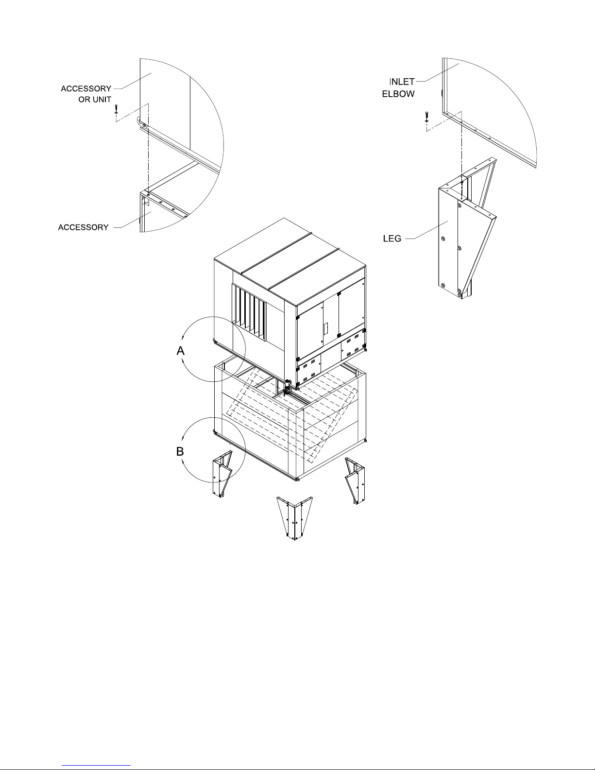
DETAIL A
DETAIL B
10. Apply a bead of latex based polyurethane caulk that
best matches the color of the exterior wall surface of
the facility and/or the color of the heater accessories
at the joint between the top inlet collar and outside
wall surface. Make certain this is a continuous bead
and that it runs the entire width of the collar. Caulk
all other exposed joints.
Cambridge Engineering, Inc. 24 M-Series Technical Manual
11. Install the discharge plenum by screwing the plenum
to the heater. Install hanging rods from the ceiling
supports to the plenum’s support brackets.
Page 27
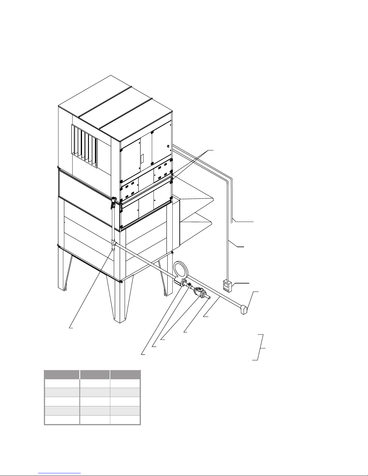
TYPICAL INSTALLATION
CONTROL WIRING CONDUIT
VERTICAL MOUNT - INDOOR CONFIGURATION
HORIZONTAL BLAST
M118 - M136
LIFTING
BRACKETS
SEDIMENT TRAP
(BY OTHERS)
Wall Opening
Model W H
M118
M120
M125
M130
M136
69" 57.5"
75" 57.5"
81" 81.5"
101.5" 81.5"
107" 81.5"
VENT PIPE
(BY OTHERS)
INLET GAS PIPE
HIGH PRESSURE SHUT-OFF VALVE
HIGH PRESSURE SUPPLY TAP
HIGH PRESSURE REGULATOR (HPR)
INCOMING POWER
7-10 WIRES (TYP)
(BY OTHERS)
RCS
VENT w/ SCREEN
(LOCATE MIN.
10 FT FROM INTAKE)
HPR
(OPTION)
M-Series Technical Manual 25 Cambridge Engineering, Inc.
Page 28

INSTALLATION INSTRUCTIONS
GAS PIPING
IMPORTANT
Refer to the heater rating plate for determining
the minimum gas supply pressure for obtaining
the maximum gas capacity for which this heater
is specified.
1. Check with the local utility or gas supplier for the
facility gas supply pressure.
mCAUTION:
If the gas supply pressure is in excess of the maximum pressure indicated on the heater nameplate,
a separate positive shut-off high pressure regulator must be added upstream of the heater’s individual manual shut-off valve. This regulator must
be vented to the outside of the building at least
10 feet from any intake opening or 4 feet above
the heater. The vent pipe should be designed to
prevent the entry of water, snow, insects or other
foreign material that could cause blockage. There
must be no reduction in the size of the vent piping. Depending on the length and the configuration
of the vent piping the pipe size may need to be
increased. Refer to the applicable codes for proper
sizing.
mWARNING:
For roof mounting, the gas and electrical connections must not penetrate the unit base or mounting
curb. Cambridge Engineering recommends using
pitch pockets or decktite to seal the penetrations.
IMPORTANT
A 1/8" NPT tap is supplied with the heater for
measuring the gas supply pressure. If the gas
supply pressure exceeds that indicated on the
nameplate, the installer must install a 1/8" NPT
tap and high pressure manual shut-off valve
upstream of the high gas pressure regulator.
IMPORTANT
An adequate sediment trap must be installed
prior to all gas controls for the heater and as
close to the gas inlet connection of the heater
as practical. Many gas train components are
equipped with listed Vent Limiters as atmospheric bleeds, however, local codes may
require that these vents and bleeds be vented
to the outdoors. If so, the vent piping should be
designed to prevent the entry of water, snow,
insects or other foreign materials that could
cause blockage.
6. Check for leaks in the supply piping system. Use
liquid gas leak detector. Do NOT use flame.
mCAUTION:
If the test pressure is in excess of 1/2 PSIG (3.5
KPA), the heater and its manual shut-off valve must
be disconnected from the gas supply system during
pressure testing. Failure to comply will void the
warranty.
If the test pressure is less than or equal to 1/2 PSIG
(3.5 KPA), the heater must be isolated from the gas
supply
piping by closing its manual shut-off valve during
pressure testing.
2. Properly size the gas supply piping for the rated
capacity, per local codes, and/or the National Fuel
Gas Code, ANSI Standard Z223.1 or the CAN/CGA
B149 Installation Codes.
3. Make sure the supply piping is free of foreign matter
and purged.
4. Verify that the gas piping, when installed, will not
restrict or block the access door from fully opening.
5. Install gas piping to the make-up air heater in
accordance with local codes or, in their absence,
in accordance with the National Fuel Gas Code,
ANSI Standard Z223.1, or the CAN/CGA B149
Installation Codes.
Cambridge Engineering, Inc. 26 M-Series Technical Manual
mCAUTION:
Do not attempt to start the
make-up air heater at this time.
Premature start-up can result in damage to the
equipment and components.
Page 29

INSTALLATION INSTRUCTIONS
ELECTRICAL
IMPORTANT
Before attempting electrical installation, review the
following instructions and wiring and connection diagrams to make sure you have a thorough understanding of what is required.
mWARNING:
High voltage electrical input to this equipment is
required. EXTREME caution should be exercised.
This equipment must be electrically grounded in
accordance with local codes or in accordance with
National Electrical Code ANSI/NFPA No. 70.
1. Check the heater nameplate to determine the voltage
and amperage requirements.
mCAUTION:
If the supply voltage does not agree with the
nameplate voltage, notify your local agent or
Cambridge Engineering’s Customer Service Group
at 800-473-4569.
mWARNING:
For roof mounting, the gas and electrical connections must not penetrate the unit base or mounting
curb. Cambridge Engineering recommends using
pitch pockets or decktite to seal the penetrations.
2. Wire the supply wiring and adequate Branch Circuit
Protection in accordance with the National Electric
Code ANSI/NFPA 70.
3. Mount the Remote Control Station in a location inside
of the building and convenient to the operator without
being susceptible to damage.
4. Space temperature sensors are normally located
along a perimeter wall and out of the direct path
of the discharge air or air infiltration. Consult the
design drawing or your local Cambridge Engineering
Representative for placement assistance. Do not
locate the remote mounted temperature sensors
immediately adjacent to overhead doors because the
infiltration air can affect the sensor when the door is
closed and may not adequately sense the temperature when the door is open. In dock areas, the sensor
should be located on the first column in from the
outside wall.
IMPORTANT
Observe the special notes and instructions on
the wiring diagrams including the following:
The wiring for the space temperature sen-
sors must be “shielded, twisted-pair” wiring
and must run separate from the other “AC”
wiring. This also applies to other remote
mounted controls utilized in the Maxitrol
Series 14 and 44 control systems. Shielded
wire which is routed to the electrical control enclosure on the heater should extend
beyond the high voltage section of the
enclosure before the shielding is terminated
and the wiring is distributed to its ultimate
destination. Shielding must be grounded on
one end only.
IMPORTANT
Conduit connections for power and control wiring must be caulked to ensure a tight seal and
prevent moisture accumulation.
5. Wire the Remote Control Station and other tem-
perature control options using Class II wiring per
Cambridge Engineering wiring diagram and National
Electrical Code Article 725 or local codes.
6. Run conduit and primary wiring to the disconnect
switch inside of the control enclosure on the heater
per N.E.C., Article 430, ANSI/NFPA 70.
7. If applicable on vertical mount, feed the cable
marked “inlet damper” through the bottom of the
heater into the inlet damper housing. Connect wiring to the damper motor junction box per the wiring
diagram.
8. Return the wiring diagram to the manual holder.
Replace and fasten all access covers.
mCAUTION:
Do not attempt to start the make-up air heater at this
time.
Premature start-up can result in damage to the
equipment and components.
M-Series Technical Manual 27 Cambridge Engineering, Inc.
Page 30

START-UP INSTRUCTIONS
1. Visual Inspection Of Equipment
(page 28)
2. Electrical Supply Voltage Verification
(page 28)
3. Gas Supply Pressure Verification
(page 29)
4. Blower Rotation Check
(page 29)
5. Burner Profile Damper Pressure Drop Check
(page 29)
6. Motor Amp Draw Check
(page 30)
7. Calculating and Adjusting
Burner Manifold Pressure
(page 30)
8. Gas Valve Leak Check
(page 31)
9. Gas Train Leak Check
(page 32)
IMPORTANT
Read the following instructions carefully. Any
unauthorized modifications to, or deviations
from these instructions may void the warranty.
1. VISUAL INSPECTION OF EQUIPMENT
a. Check for any physical damage from ship-
ping or installation that could render the heater
inoperable.
b. Verify all heater accessories and filters (if
applicable) have been properly installed.
c. Check for loose components (belts, plugs, ter-
minal screws, etc.).
d. Verify the access doors and controls enclosure
are free from obstructions, such that they can
be fully opened.
e. Verify the field wiring, both primary and
control, has been installed according to the
Cambridge Engineering wiring diagram and
the National Electrical Code.
10. Minimum Fire Setting
(page 32)
11. Low Fire Start Adjustment
(page 33)
12. Preliminary Remote Control Station
Operational Check
(page 33)
13. Final Heater Preparation
(page 34)
14. Final Remote Control Station Check
(page 34)
After start-up, please complete and fax the M-Series
Start Up Checklist to the Cambridge Customer Service
Group. Receipt of a completed checklist will extend
the start date for your warranty period to the date of the
start-up but not to exceed six months from date of shipment.
f. Verify that a sediment trap has been provided
upstream of other gas train components.
g. Verify the high pressure regulator and/or vent
valve, if applicable, have been vented to the
outside of the building at least 10 feet from
any intake opening or 4 feet above the heater.
h. Verify the factory supplied manual gas shut-
off cock is installed external to the heater and
downstream of the high pressure regulator, if
applicable.
i. Verify that the gas piping unions are tight.
j. Verify that the burner union is tight.
2. ELECTRICAL SUPPLY VOLTAGE
VERIFICATION
For model M110 - M115 heaters, remove electri-
cal enclosure access door and check the electrical
supply voltage at the terminal block provided off
Cambridge Engineering, Inc. 28 M-Series Technical Manual
Page 31

of the disconnect switch. For model M118 - M140
heaters, check the electrical supply voltage at the
disconnect switch.
mCAUTION:
Do not proceed with start-up unless the supply
voltage agrees with the nameplate voltage. If the
supply voltage does not agree with the nameplate voltage, check with your local Cambridge
Engineering representative or Cambridge
Engineering’s Customer Service Group at 800473-4569 to determine what changes are required.
3. GAS SUPPLY PRESSURE VERIFICATION
Verify that the gas supply pressure complies with the
heater nameplate.
b. Turn the blower service switch to the “LOCAL”
position. The blower motor will start after the
motorized inlet damper opens. Then turn the
blower service switch to the
“OFF” position and
verify the blower is rotating in the proper direction.
(See the directional arrow on the blower housing.)
IMPORTANT
On a three phase system, the rotation direction of the
blower may be reversed by switching any two wires located on the downstream side of the service disconnect.
The electrical supply to the heater must be turned off
prior to switching the wiring.
IMPORTANT
Indications of loose belts include barking or squealing when the blower starts. If these symptoms occur,
please refer to the BELT TENSIONING section of
the MAINTENANCE INSTRUCTIONS (see page 59).
Periodic belt adjustments may be required.
mCAUTION:
Do not proceed with start-up unless the gas supply pressure agrees with the nameplate pressure
requirements. If the gas supply pressure is in
excess of the maximum pressure indicated, a separate positive shut-off high pressure regulator must
be added upstream of the heater’s individual low
pressure manual shut-off valve. If a high pressure
regulator is needed and has not been installed,
check with your local Cambridge Engineering representative or Cambridge Engineering’s Customer
Service Group at 800-473-4569 to determine the
size and capacity requirements that are required.
4. BLOWER ROTATION CHECK
a. Open the access door on the electrical control enclosure
side and turn the disconnect switch on.
mWARNING:
When the disconnect switch is activated with the
enclosure open, live power is present. Only experienced technicians with knowledge and respect for
live power should proceed beyond this point.
5. BURNER PROFILE DAMPER PRESSURE
DROP CHECK
IMPORTANT
The blower access doors must be in place when adjusting the profile plate.
IMPORTANT
Verify that the inclined manometer, if applicable, is
level and zeroed for proper readings to be obtained.
a. Turn the blower service switch to the “LOCAL”
position. (Note: The burner service switch must
remain in the “OFF” position)
b. Check the pressure drop across the burner prole
plate to ensure that it complies with the table
below:
Profile Plate Pressure Drop -
Blower Only (inches WC)
Gas
Type
Natural
LP
Models Filters
M110-M140 No 0.68
M140 Yes 0.75
M110-M140 No 0.90
M110-M136 Yes 0.94
M140 Yes 0.97
Manual
Adjust
Automatic
Adjust
Min. Max.
0.62 0.72M110-M136 Yes 0.72
0.84 0.94
M-Series Technical Manual 29 Cambridge Engineering, Inc.
Page 32
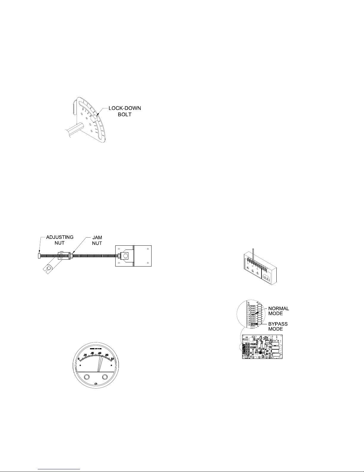
c1. To change the prole plate pressure drop on
model M110 - M115 heaters with a Manual
Prole Adjust mechanism, locate the adjusting mechanism in the electrical control enclosure, loosen the lock-down bolt, and rotate the
adjuster to increase or decrease the pressure
as required. Retighten the lock-down bolt to
secure the mechanism.
IMPORTANT
Call the Cambridge Engineering Customer Service
Group at 800-473-4569 if unable to obtain the required
pressure drop across the burner profile plate.
o 6. MOTOR AMP DRAW CHECK
IMPORTANT
The heater access doors must be closed for this test.
a. Check the motor current at the overload relay
on all three legs.
b. Turn the blower service switch to the “OFF”
position.
c2. To change the prole plate pressure drop on
model M118 - M140 heaters with a Manual
Prole Adjust mechanism, locate the adjusting
mechanism in the gas train enclosure, loosen
the jam nut, and rotate the adjusting nut to
increase or decrease the pressure drops, as required. Hold the adjusting nut and retighten the
jam nut to secure the mechanism.
c3. For make-up air heaters with an Automatic
Prole Adjust system, check the Differential
Pressure Switch/Gauge and verify that the left
orange needle is set to the Minimum setting and
the right orange needle is set to the Maximum
setting from the table above.
IMPORTANT
The average amps must not exceed the motor nameplate
FLA. High amperage may indicate excessive blower
RPM. Call the Cambridge Engineering Customer
Service Group at 800-473-4569 if unable to obtain ac-
ceptable amperage readings.
7. CALCULATING AND ADJUSTING BURNER
o
MANIFOLD PRESSURE
Cambridge Engineering, Inc. 30 M-Series Technical Manual
a. Turn the disconnect switch off.
b. Disconnect #3 wire from the amplifier to drive the
modulating valve to full open.
c. If the ambient temperature is at or above the
Entering Air Thermostat (EAT) setpoint on
the multi-functional PC board, then note the
setpoint position and set the EAT to its highest
Page 33

setting. If the ambient temperature exceeds its
highest setting, remove the set point jumper
and rotate 90˚ for the bypass mode.
d. Remove the 1/8" NPT plug from the manual
shut-off valve located just prior to the burner
and connect a manometer for the purpose of mea-
e. Refer to the heater nameplate for the Manifold
suring the manifold pressure.
Differential Pressure (MDP) (inch WC) for
which the heater was specified.
below 0.51 inches WC for natural gas heaters without
filters or 0.55 inches WC for natural gas heaters with
a filter section or filters in the rainhood. The pressure
drop must not fall below 0.75 inches WC for LP gas
heaters without filters or 0.79 inches WC for LP gas
heaters with a filter section or filters in the rainhood. If
the pressure drop is below these values, it is an indication of low airflow or burner overfiring. To correct this
condition, either adjust the manifold pressure regulator
to reduce the manifold pressure or increase the blower
speed, provided the motor full load amps are not exceeded.
Nameplate Manifold Differential Pressure
f. Turn the disconnect switch on.
g. Turn the blower service switch to the
“LOCAL” position. The blower motor will
start. Monitor the pressure reading on the manometer. Record the Manifold Static Pressure (Blower
Only).
h. Using the formula below, calculate the required
manifold pressure:
Nameplate Manifold Differential Pressure
___________inch WC
+ Manifold Static Pressure (Blower Only)
___________inch WC
= Calculated Manifold Pressure
___________inch WC
IMPORTANT
The high limit may trip on warm or mild temperature
days. A jumper may be necessary to complete the manifold pressure adjustment.
i. Turn the burner service switch to the
“LOCAL” position. After a delay for pre-
purge and igniter warm-up, the burner will
light.
j. Observe the manometer reading and compare
to the Calculated Manifold Pressure above. If
the manifold pressure reading does not equal this
value, adjust the manifold pressure regulator
until the proper manifold pressure is obtained.
k. Turn the blower and burner service
switches to the “OFF” position, remove
the manometer from the manual shut-off
valve, re-install the 1/8" NPT plug and
remove the jumper (if used).
o 8. GAS VALVE LEAK CHECK
All heaters should be evaluated for the gas tight-
ness of the gas valve seat. Heaters with separate
redundant valves are equipped with a leak test facility to assist in checking this seal. A momentary switch
and a gas port for measuring pressure between
valves are provided as the leak test hardware.
Refer to the Individual Component Description
Section for more information regarding the leak
test switch. The procedures for the gas valve leak
check are as follows:
a. Connect a 0 to 10 inches water column
(
inch WC) manometer to the 1/8" NPT
tapped fitting on the manual shut-off
valve located just prior to the burner for
the purpose of monitoring an increase in
pressure. Verify that the manometer is
properly zeroed.
b.1. On single redundant valve applications
(heaters rated less than 400,000 Btu/hr),
close the manual burner shut-off valve
and wait 30 seconds to read the manom-
eter. If the reading is greater than 0
inch
WC, replace the gas valve and retest. If the
reading is 0 inch WC, remove the manometer and reinstall the pipe plug.
IMPORTANT
The pressure drop across the burner profile damper
that was adjusted in Step 5 (page 30) must not fall
M-Series Technical Manual 31 Cambridge Engineering, Inc.
b.2. On heaters with separate redundant
valves, close the manual burner shutoff valve, hold the momentary leak test
Page 34
switch in the closed position, and wait
30 seconds to read the manometer. If the
reading is greater than 0
to the Maintenance Instruction Section for
information on Gas Valve Cleaning for
cleaning the second gas valve and retest.
If the reading is 0
manometer and reinstall the pipe plug.
c. To check the gas tightness of the first
valve in the gas train on heaters with
separate redundant valves, connect the
manometer to the leak test port between
the valves and verify that the manometer is properly zeroed. Wait 30 seconds
to read the manometer. If the reading
is greater than 0
Maintenance Instruction Section for information on Gas Valve Cleaning for the
first gas valve and retest. If the reading is
0
inch WC, remove the manometer and
reinstall the pipe plug.
inch WC, refer to the
inch WC, refer
inch WC, remove the
from the amplifier.
b. Connect a meter set to read DC micro-
amps (mA) in order to verify the minimum
fire flame signal during the adjustment
process. Connect the meter by removing
the red wire from terminal FP of the flame
safe
guard relay (FSR) and attaching the
positive lead of the meter to terminal FP
and the negative lead to the red wire.
c. Turn the blower and burner switches to
the “LOCAL” position.
d. After the burner has ignited remove #8
wire from the amplifier to drive the modulating valve to minimum fire.
e. Look through the burner porthole in the
front of the heater to verify that the burner
flame is a very small ribbon (approxi-
mately 1-1/2" to 2
spread across the burner (without gaps).
" long) that is evenly
9. GAS TRAIN LEAK CHECK
o
a. Turn the blower and burner service
switches to the “LOCAL” position.
b. With the burner operating, spray the com-
plete gas train with leak detector solution,
checking all pipe connections and plugs.
c. Turn the blower and burner service
switches to the “OFF” position.
mWARNING:
Do not use flame to leak check piping.
mWARNING:
Any gas leak detected must be repaired before the
make-up air heater is placed into service.
10. MINIMUM FIRE SETTING
f. Verify that the minimum fire flame signal
is steady and above 2.0 microamps (mA).
IMPORTANT
If any of the conditions in steps 10.e and 10. f are not
met, an adjustment is required.
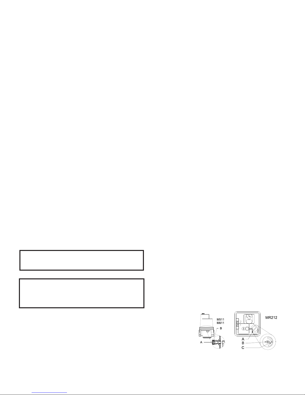
g. Minimum Fire Adjustment
i. To adjust the minimum fire, remove
cap (A) exposing the minimum fire adjusting screw.
On the MR212 modulating/
regulating valve, remove the housing
cover, then cap (A), and then loosen
lock screw (C). Turn the adjusting
screw (B) to obtain the desired minimum fire setting. Repeat steps 10.e
and 10.f.
IMPORTANT
All access doors must be closed during this procedure.
a. Reinstall the #3 wire previously removed
Cambridge Engineering, Inc. 32 M-Series Technical Manual
Page 35
. ii. Replace the cap (A). Tighten the lock
screw (C) on the MR212 valve prior
to reinstalling the cap and housing
cover.
iii. Turn the blower and burner service
switches to the “OFF” position.
iv. Reconnect wire #8 to the amplifier.
v. Remove the meter and reattach the red
wire to terminal FP on the FSR board.
11. LOW FIRE START ADJUSTMENT
The Low Fire Start control setting is preset at the
factory to provide a fixed, repetitive, initial firing
rate that equates to the following for most burner
applications:
• 20˚F to 30˚F temperature rise
• 0.10 to 0.30 inches WC manifold differential
pressure (above blower pressure)
• Voltage to the modulating valve of 9 to 11 Volts
DC for the Maxitrol M511 or M611 valve and 10
to 13 Volts DC for the Maxitrol MR212 valve.
• Flame length of 3" to 5"
The Low Fire Start function lasts for 15 seconds
before returning to the control of the temperature
control system. It is important that the flame travels
across the burner length fast enough (within 2 seconds) to establish the flame signal during the trial for
ignition period. If adjustment is required, proceed as
follows:
a. Connect a meter in the flame sense circuit
as in step 10.b (see page 33).
b. Connect a manometer to the burner static
pressure port. Turn the blower service
switch to the “LOCAL” position and the
burner service switch to the “OFF” position and measure the burner static pressure.
c. Connect a DC voltmeter to terminals “MV
OUT” on the multi-functional PC board.
d. Turn the burner service switch to the
“LOCAL” position and monitor the modu-
lating valve voltage, flame length, manifold
differential pressure, and the time required
to establish flame signal after the gas
valves are energized. (This may need to
be repeated several times to note all of the
above information)
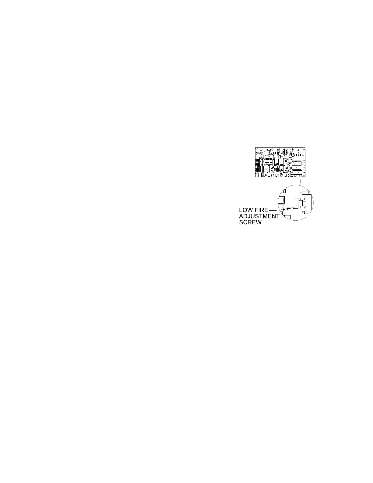
e. If adjustment is required, the Low Fire
Start adjustment screw is located on the
multi-functional PC board as shown in
the drawing. Only minor adjustments are
normally required to obtain the proper setting.
12. PRELIMINARY REMOTE CONTROL
STATION OPERATIONAL CHECK
a. Turn the blower and burner service switches
to the “REMOTE” position and, if applicable, turn the Remote Control Station mode
selector switch to the “HEATING” position.
b. Identify the type of Remote Control Station,
if applicable, that is utilized on this application. Refer to Individual Component
Description Section for additional information.
c.1. If the Remote Control Station utilizes
a thermostat, refer to the Operating
Instructions for the Electronic Thermostat
(see page 65) or the TSS Controller (see
page 67) to set the thermostat at its highest setting.
c.2. If another device in the Remote Control
Station controls the operation of the heater,
activate this device.
M-Series Technical Manual 33 Cambridge Engineering, Inc.
Page 36

c.3. If the make-up air heater is not equipped
with a Remote Control Station, activate
that part of the control system which will
initiate the blower and burner operation.
d. After a short delay for damper operation,
the blower should operate, followed by
burner ignition after a delay for prepurge
and igniter warm-up.
14. FINAL REMOTE CONTROL STATION
CHECK
a. To ensure the heater’s disconnect and service
switches have been left in the correct position, turn the mode selection switch to the
“SUMMER VENTILATION” position and
verify the blower operates.
e. Adjust the applicable temperature control
and verify the heater output changes.
f. Reset the thermostat, if applicable, and the
temperature control to the desired temperature.
g. Turn the mode selector switch to the
“SUMMER VENTILATION” position.
Verify the blower operates.
13. FINAL HEATER PREPARATION
a. Turn the disconnect switch off.
b. Set the Entering Air Thermostat (EAT) to
the specified temperature setting. Refer
to the Individual Component Description
Section for additional information.
c. Remove the jumper wire from the high
limit, if one was used. Reset the high
limit.
SHUT-DOWN INSTRUCTIONS
1. Turn the mode selector switch of the
Remote Control Station to the “OFF”
position.
2. Turn the service disconnect switch off.
3. Turn the blower and burner service
switches to the “OFF” position.
4. Close the supply gas cock.
5. Turn off the electric supply to the heater.
IMPORTANT
If you need technical assistance, call the Cambridge
Engineering Customer Service Group at 800-473-4569
during the hours of 8:00 a.m. to 5:00 p.m. Central
Time, Monday through Friday.
d. For the Maxitrol Series 44 control system,
set the “MIN” and “MAX” setting of the
amplifier to the application specifications.
e. Verify the blower and burner service
switches are in the “REMOTE” position.
f. Return the Technical Manual and Wiring
Diagram to the manual holder.
g. Perform a visual inspection of all wiring and
gas valve plugs to ensure they have been
properly replaced.
h. Replace and fasten all covers and panels.
Turn the disconnect switch on.
Cambridge Engineering, Inc. 34 M-Series Technical Manual
Page 37
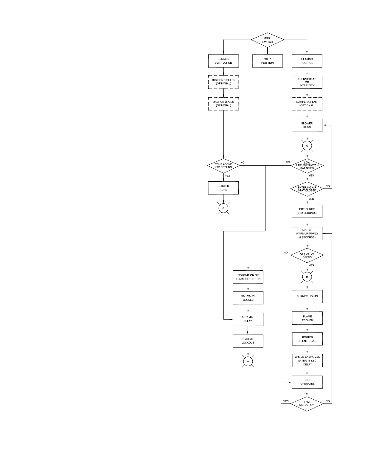
OPERATING INSTRUCTIONS
OPERATING SEQUENCE
POWER ON
1. Control transformer energized.
2. Operator must select “SUMMER
VENTILATION” or “HEATING” mode.
SUMMER VENTILATION MODE
1. Mode switch in “SUMMER VENTILATION”
position.
2. Optional TSS Controller schedule calls for ventilation.
3. Optional motorized inlet or discharge damper
opens.
4. Blower motor starts.
5. Unit continues to run until turned off.
HEATING MODE
1. Mode switch in “HEATING” position.
2. Thermostat or interlock calls for heat.
3. Optional motorized inlet or discharge damper
opens.
4. Blower motor starts.
5. Low airflow switch closes.
6. Entering air thermostat closes when inlet temperature is below setpoint after the prepurge delay.
7. Igniter warm up timing.
8. Gas valve opens.
9. Burner lights.
10. Igniter is de-energized.
11. Low Fire Start is de-energized after 15 seconds.
12. Unit runs and modulates until operating thermostat
and/or interlock opens (heater shuts off).
13. Steps (2) through (12) repeat themselves automatically as necessary.
M-Series Technical Manual 35 Cambridge Engineering, Inc.
Page 38

OPERATING INSTRUCTIONS
ELECTRONIC THERMOSTAT
The Cambridge Engineering Operating Electronic Thermostat (OET) controls the heater’s ON/OFF
operation in a space heating mode. It includes the following features:
• Digital LED display of current temperature and temperature settings.
• LED indication of status of output relay.
• Separate settings for HEAT ON and HEAT OFF settings.
• Temperature Calibration for accurate temperature control.
• EEPROM storage maintains temperature settings indefinitely in case of power loss.
The thermistor enclosure (SH-1) is packed inside the Remote Control Station for shipment. It can be
mounted on the exterior sides or bottom of the Remote Control Station or a remote location within
500 feet of the Remote Control Station using 18 gauge stranded, twisted-pair, shielded cable. The
thermistor is hard wired to the temperature sensor terminal block.
Cambridge Engineering, Inc. 36 M-Series Technical Manual
Page 39

SETTING TEMPERATURES
TEMPERATURE CALIBRATION
The Electronic Thermostat requires two temperature settings. When the temperature drops below the HEAT ON
setting, the heater will turn on. When the heater raises
the space temperature above the HEAT OFF setting, the
heater will turn off. This difference provides an adjustable range of operation for the heater which minimizes
temperature swings.
The minimum run time and off time for the heater
regardless of temperature are both set at 2 minutes. The
allowable temperature range is 40°F to 99°F. The HEAT
OFF temperature can not be set lower than the HEAT
ON temperature.
1. Press and hold the HEAT ON button while pressing
the UP or the DOWN button until the desired temperature for the heater to turn ON is displayed.
To compensate for lead wire resistance, it may be necessary to make an adjustment to the displayed temperature
to correct it to the temperature measured at the thermistor sensor. The calibration feature allows the displayed
temperature to be offset either above or below the actual
sensed temperature. Be sure to use an accurate temperature meter for making this correction.
1. Press and hold the HEAT ON and HEAT OFF buttons
while pressing the UP or the DOWN button until the
correct temperature is displayed. ( A period [.] after
the temperature will indicate the Calibration Mode).
2. Press and hold the HEAT OFF button while pressing
the UP or the DOWN button until the desired temperature for the heater to turn OFF is displayed.
2. Pressing the UP or the DOWN button will display the
current calibration difference above or below (-) the
measured temperature.
M-Series Technical Manual 37 Cambridge Engineering, Inc.
Page 40

OPERATING INSTRUCTIONS
TSS CONTROLLER
The Cambridge Engineering TSS Controller provides several features to tailor the operation of the Cambridge
heating system to particular applications.
• Seven day programmable clock.
• Separate temperature settings for Heating and Setback operation.
• Separate schedules for Summer Ventilation and Heating modes.
• Setback Override for temporary heating operation.
• Real-Time Clock with automatic adjustment for Daylight Saving Time.
• Nine Holiday Setback Periods for temporary setback operation.
• Temperature Calibration for accurate temperature control.
• Capacitor backup maintains current time and day of week for power loss of up to 96 hours.
• EEPROM storage maintains schedules and temperature settings indefinitely.
The thermistor enclosure (SH-1) is packed inside the Remote Control Station for shipment. It can be mounted
on the exterior sides or bottom of the Remote Control Station or a remote location within 500 feet of the Remote
Control Station using 18 gauge stranded, twisted-pair, shielded cable. The thermistor is hard wired to the temperature sensor terminal block.
Cambridge Engineering, Inc. 38 M-Series Technical Manual
Page 41

SETTING CURRENT DAY OF WEEK, TIME,
MONTH/DAY, AND YEAR
For proper operation of the scheduler, the TSS
Controller clock must be set to the correct day of week,
time, month/day and year. In the event of power loss of
more than 96 hours, these settings must be updated.
During normal operation, the TSS Controller display
will alternate between the current space temperature and
the current time and day of the week.
1. Press and hold the DAY OF WEEK button while
pressing the UP or the DOWN button until the light
for the current day is illuminated.
3. Press and hold the MONTH/DAY button while pressing the UP or the DOWN button until the current date
is displayed.
4. Press and hold the YEAR button while pressing the
UP or the DOWN button until the current year is dis-
played.
2. Press and hold the TIME button while pressing the
UP or the DOWN button until the current time is dis-
played.
SETTING AUTOMATIC ADJUSTMENT FOR
DAYLIGHT SAVING TIME
The TSS Controller has the ability to automatically
detect and adjust for daylight saving time. The default
setting on the controller is to recognize daylight saving
time.
M-Series Technical Manual 39 Cambridge Engineering, Inc.
Page 42

SETTING TEMPERATURES
1. Press the SETBACK SCHEDULE/EXIT button to enter
the scheduling program at the first ON cycle.
2. Press the UP button once to enter the daylight saving
time setting ("d-SA" is displayed).
The TSS Controller has two temperature control modes
with the keyswitch on the front of the enclosure in the
HEATING position. The HEATING mode controls
the heater when the ON time schedule is in effect. The
SETBACK mode controls the heater when the OFF time
schedule is in effect. (See SETTING SCHEDULES for
instructions on setting the ON and OFF schedules). With
the keyswitch in the SUMMER VENTILATION position the heater fan will run based on the time schedule
with no temperature control.
HEATING MODE (ON Time Schedule)
The HEATING mode requires two temperature settings.
When the temperature drops below the HEAT ON setting the heater will turn on. When the heater raises the
space temperature above the HEAT OFF setting, the
heater will turn off. This difference provides an adjustable range of operation for the heater, which minimizes
temperature swings. The minimum on time and off time
for the heater regardless of temperature is 2 minutes. The
allowable temperature range is 41°F to 99°F.
3. Press and hold the YEAR button while pressing the
UP or the DOWN button to scroll to "YES" if daylight
saving time should be recognized or "NO" if daylight
saving time is not recognized.
The HEAT OFF temperature cannot be set lower than
the HEAT ON temperature.
1. Press and hold the HEAT ON button while pressing
the UP or the DOWN button until the desired temperature for the heater to turn ON is displayed.
4. Press the SETBACK SCHEDULE/EXIT button to exit
the scheduling program.
Cambridge Engineering, Inc. 40 M-Series Technical Manual
Page 43

2. Press and bold the HEAT OFF button while pressing
the UP or the DOWN button until the desired temperature for the heater to turn OFF is displayed.
SETBACK MODE (OFF Time Schedule)
The SETBACK mode requires setting only the ON temperature. The OFF temperature will be automatically
set based on the temperature difference between HEAT
ON and HEAT OFF programmed above for the HEAT
mode.
1. Press and hold the SETBACK TEMP. button while
pressing the UP or the DOWN button until the desired
temperature for the heater to turn ON is displayed.
SETTING SCHEDULES
The TSS Controller has separate programmable daily
schedules for the HEATING and the SUMMER
VENTILATION modes. The schedule currently in
effect is determined by the position of the keyswitch
in the door of the enclosure. With the keyswitch in
the HEATING or OFF position, the schedule for the
Heating Mode is accessible. With the keyswitch in the
SUMMER VENTILATION position, the schedule for
the Ventilation Mode is accessible. (This will be indicated by the VENT MODE light on the TSS Controller
being illuminated). Before attempting to program the
schedule, determine the planned time periods for HEAT
(ON) and SETBACK (OFF) for the HEATING mode
and the planned ON and OFF time periods for the
Ventilation mode. The time that it takes to recover from
the SETBACK temperature to the HEAT temperature
must also be taken into consideration for the ON time
in the HEATING mode. The following charts can be
filled in for a reference during the programming of
the schedule. There are fifteen available ON and OFF
program cycles for both HEATING and SUMMER
VENTILATION. The first ON and OFF cycles are fixed
for Monday through Friday and should only be used
when the schedules for those days are identical. The
fourteen additional numbered cycles can be programmed
for any one day or successive days.
SETBACK OVERRIDE
In instances where temporary heat is desired when the
scheduler is in the SETBACK mode, the OVERRIDE
timer can be used. Setting this timer, located on the front
of the TSS panel, will override the SETBACK temperature setting and increase the space temperature to the
HEAT ON and HEAT OFF temperature settings for the
amount of time set on the OVERRIDE timer.
NOTE: Do not program the TSS controller with overlapping schedules, as operational errors will occur.
Whenever the heater is operating during a scheduled ON
cycle and a subsequent overlapping program is encountered, that program will be ignored.
A Holiday Setback Schedule is available for temporary
operation in the Setback Mode of up to nine different
holiday periods without affecting the current schedules.
(See HOLIDAY SETBACK SCHEDULE section for
instructions on using this feature).
All unused program cycles should not contain any settings. Check all cycles after programming to assure that
the display for unused cycles shows "--:--". If undesired
settings have been entered, scroll the time display until
"--:--" is displayed (between 11.59PM and 12.00AM for
time settings; between 12.31 and 1.01 for date settings).
M-Series Technical Manual 41 Cambridge Engineering, Inc.
Page 44
HEATING SCHEDULE
Cycle Time AM/PM Day
On
Off
On 1
Off 1
On 2
Off 2
On 3
Off 3
On 4
Off 4
On 5
Off 5
On 6
Off 6
On 7
Off 7
On 8
Off 8
On 9
Off 9
On 10
Off 10
On 11
Off 11
On 12
Off 12
On 13
Off 13
On 14
Off 14
M-F
M-F
SUMMER VENTILATION SCHEDULE
Cycle Time AM/PM Day
On
Off
On 1
Off 1
On 2
Off 2
On 3
Off 3
On 4
Off 4
On 5
Off 5
On 6
Off 6
On 7
Off 7
On 8
Off 8
On 9
Off 9
On 10
Off 10
On 11
Off 11
On 12
Off 12
On 13
Off 13
On 14
Off 14
M-F
M-F
Cambridge Engineering, Inc. 42 M-Series Technical Manual
Page 45

1. Switch the keyswitch on the front of the enclosure to
the desired operating mode. Allow ten seconds before
proceeding.
2. Press the SETBACK SCHEDULE/EXIT button to enter
the scheduling program at the first ON cycle.
3. Press and bold the TIME button while pressing the UP
or the DOWN button to scroll to the desired ON time
for Monday through Friday.
5. Press and bold the TIME button while pressing the UP
or the DOWN button to scroll to the desired OFF time
for Monday through Friday.
6. If Monday through Friday is the only schedule
required, proceed to Step 14. If any additional programming is required, proceed with the following
steps. Remember that subsequent program cycles must
not overlap with the ON and OFF times set above.
7. Press the UP button once to step to the next ON cycle.
4. Press the UP button once to step to the first OFF
cycle.
M-Series Technical Manual 43 Cambridge Engineering, Inc.
8. Press and bold the TIME button while pressing the UP
or the DOWN button to scroll to the desired ON time.
9. Press and bold the DAY OF WEEK button while
pressing the UP or the DOWN button until the light
for the desired day is illuminated.
Page 46
10. Press the UP button once to step to the next OFF
cycle.
11. Press and hold. the TIME button while pressing the
UP or the DOWN button to scroll to the desired OFF
time.
12. Press and hold the DAY OF WEEK button while
pressing the UP or the DOWN button until the light
for the desired day is illuminated.
13. Repeat steps 7-12 until all required program cycles
have been entered.
14. Press the SETBACK SCHEDULE/EXIT button to exit
the scheduling program.
15. Verify that the correct current time and light for day
of the week are still displayed.
HOLIDAY SETBACK SCHEDULE
The Holiday Setback Schedule overrides the normal
schedule and holds the space at the SETBACK temperature. The TSS Controller allows up to nine holiday periods (Holiday Start Date [HSD] and Holiday End Date
[HED]) to be scheduled.
HOLIDAY SETBACK SCHEDULE
Cycle Date
HSD 1
HED 1
HSD 2
HED 2
HSD 3
HED 3
HED 4
HED 4
HSD 5
HED 5
HSD 6
HED 6
HSD 7
HED 7
HSD 8
HED 8
HSD 9
HED 9
Cambridge Engineering, Inc. 44 M-Series Technical Manual
Page 47

1. Press the SETBACK SCHEDULE/EXIT button to enter
the scheduling program at the first ON cycle.
4. Press the UP button once to step to the first holiday
end date cycle (HEd1).
2. Press the UP button repeatedly to step to the first holiday start date (HSd1).
3. Press and hold. the MONTH/DAY button while pressing the UP or the DOWN button to scroll to the
desired holiday start date.
5. Press and hold the MONTH/DAY button while pressing
the UP or the DOWN button to scroll to the desired
holiday end date. (NOTE: Holiday end date must be at
least one day after holiday start date).
6. Repeat steps 2-5 until all required holiday cycles have
been entered.
7. Press the SETBACK SCHEDULE/EXIT button to exit
the scheduling program.
M-Series Technical Manual 45 Cambridge Engineering, Inc.
Page 48

TEMPERATURE CALIBRATION
To compensate for lead wire resistance, it may be necessary to make an adjustment to the displayed temperature
to correct it to the temperature measured at the thermistor sensor. The calibration feature allows the displayed
temperature to be offset either above or below the actual
sensed temperature. Be sure to use an accurate temperature meter for making this correction.
1. Press and hold the HEAT ON and HEAT OFF buttons
while pressing the UP or the DOWN button until the
correct temperature is displayed. (A period [.] after the
F will indicate the Calibration Mode).
2. Pressing the UP or the DOWN button will display the
current calibration difference above or below (-) the
measured temperature.
Cambridge Engineering, Inc. 46 M-Series Technical Manual
Page 49

MAINTENANCE INSTRUCTIONS
mWARNING:
Turn the disconnect switch off when performing
service or maintenance functions.
BLOWER BEARING LUBRICATION
Heaters with 3 HP or smaller motors have permanently
lubricated, double shielded, and double sealed ball bearings which do not require additional lubrication. Heaters
with 5 HP or larger motors require lubrication on intervals of 3 to 6 months. Use Shell Alvania #2, Exxon
Unirox N2, Mobil Mobilith SHC100, Mobil 532, Mobil
Mobilux #2, Texaco Multifak #2 and Texaco Premium
RB lubricants.
MOTOR BEARING LUBRICATION
Motors are pre-greased normally with Shell Dolium R.
Equivalent greases which are compatible with the motor
furnished grease are Chevron SRI No. 2 and Texaco
Premium RB
Annual Motor Op-
Intermittent Operation
- >5000 hours
Continuous Operation
- Standard Service
Seasonal Service
(Motor is idle for 6
months or more)
Continuous Operation
- Severe Service
(High ambient, dirty
or moist location, high
.
eration
vibration)
Recommended Lubrica-
tion Interval
NEMA 215T
Frame or
smaller
5 years 3 years
2 years 1 year
1 year 1 year
6 months 6 months
NEMA 254
Frame or
larger
BELT TENSIONING
Using a Browning Belt Tension Checker and a straight
edge, verify proper belt tension exists according to
the following table. Periodic belt adjustments may be
required. Indications of loose belts include barking or
squealing when blower starts.
Center
Span
Deec-
tion
5VX 9/16" 9-11 8-10
Force (lbs)
New
Belts
6½ -
8½
6½ -
8½
6½ -
8½
6½ -
8½
6½ -
8½
6½ -
8½
8½ 10½
Used
Belts
6 - 7½
6 - 7½
6 - 7½
6 - 7½
6 - 7½
6 - 7½
4½ -
6½
8-10
Model
M110-
M112
M110-
M115
M112-
M118
M115
M118-
M120
M118-
M120
M120
M120
M125
M125-
M130
M125-
M130
M125-
M130
M130-
M136
M130-
M136
M130-
M136
M130-
M136
M136-
M140
M136-
M140
M140
M140
M140
M140
Belt(s)
Motor
HP
7½ 2 BX 7/16" 6 - 8 5½ - 7
7½ 2 BX 9/16" 6 - 8 5½ - 7
50-60 6 BX 9/16" 7-9 6-8
50-60
Qty Type
1 1 A 1/4" 2 - 3 1 - 2
2 1 A 1/4" 2½ - 4 1½ - 3
3 1 BX 1/4" 4½ - 6 4 - 5½
5 2 BX 1/4" 3 - 5 2½ - 4
5 2 BX 7/16" 5 - 7
10 2 BX 7/16"
15 2 BX 7/16" 7 - 9 6 - 8
10 2 BX 9/16"
15 2 BX 9/16" 7 - 9 6 - 8
20 3 BX 9/16"
25 3 BX 9/16" 7 - 9 6 - 8
25 4 BX 9/16"
30 4 BX 9/16"
30 3 5VX 9/16" 7 - 9 6 - 8
40 5 BX 9/16"
40 3-4 5VX 9/16" 8 - 10 7 - 9½
4 or
5
75 5 5VX 9/16" 10-12 9-11
75 6 5VX 9/16"
M-Series Technical Manual 47 Cambridge Engineering, Inc.
Page 50

REFERENCE
HEATER ROOF AND WALL OPENINGS
Horizontal Mount
Wall Opening
Discharge Inlet
Model W H W H W L
M110
M112
M115
M118
M120
M125
M130
M136
M140
18.25" 18.25" 32" 35.25" 19.25" 19.25"
19.75" 19.75" 32" 35.25" 20.75" 20.75"
22.75" 22.75" 46" 35.25" 23.5" 23.75"
25.5" 25.5" 50" 55" 26.5" 26.5"
29.5" 29.5" 56" 55" 30.5" 30.5"
35" 35" 68" 71.75" 36" 36"
41" 41" 89.75" 71.75" 42" 42"
47" 47" 89.75 96.75" 48" 48"
54" 54" 119.5" 101" 55" 55"
Vertical Mount
Wall Opening
Discharge Inlet
Model W H W H
M118
M120
M125
M130
M136
1
Based on 2" added to both the length and width of the discharge duct
2
Based on 3" added to both the length and width of the discharge duct
25.5" 25.5" 69" 57.5"
29.5" 29.5" 75" 57.5"
35" 35" 81" 81.5"
41" 41" 101.5" 81.5"
47" 47" 107" 81.5"
1
Roof
Opening
1
2
HEATER DISCHARGE DIMENSIONS
Discharge Opening Discharge Duct Size
Model W L W L
M110
M112
M115
M118*
M120*
M125*
M130*
M136*
M140
*Applies to both horizontal and vertical mount
Cambridge Engineering, Inc. 48 M-Series Technical Manual
12.7" 13.6" 16.25" 16.25"
12.9" 15.9" 17.75" 17.75"
18.6" 15.9" 20.75" 20.75"
21.9" 18.7" 23.5" 23.5"
24.5" 24.7" 27.5" 27.5"
31.2" 31.2" 33" 33"
36.6" 36.6" 39" 39"
42.5" 42.8" 45" 45"
50" 50" 52" 52"
Page 51
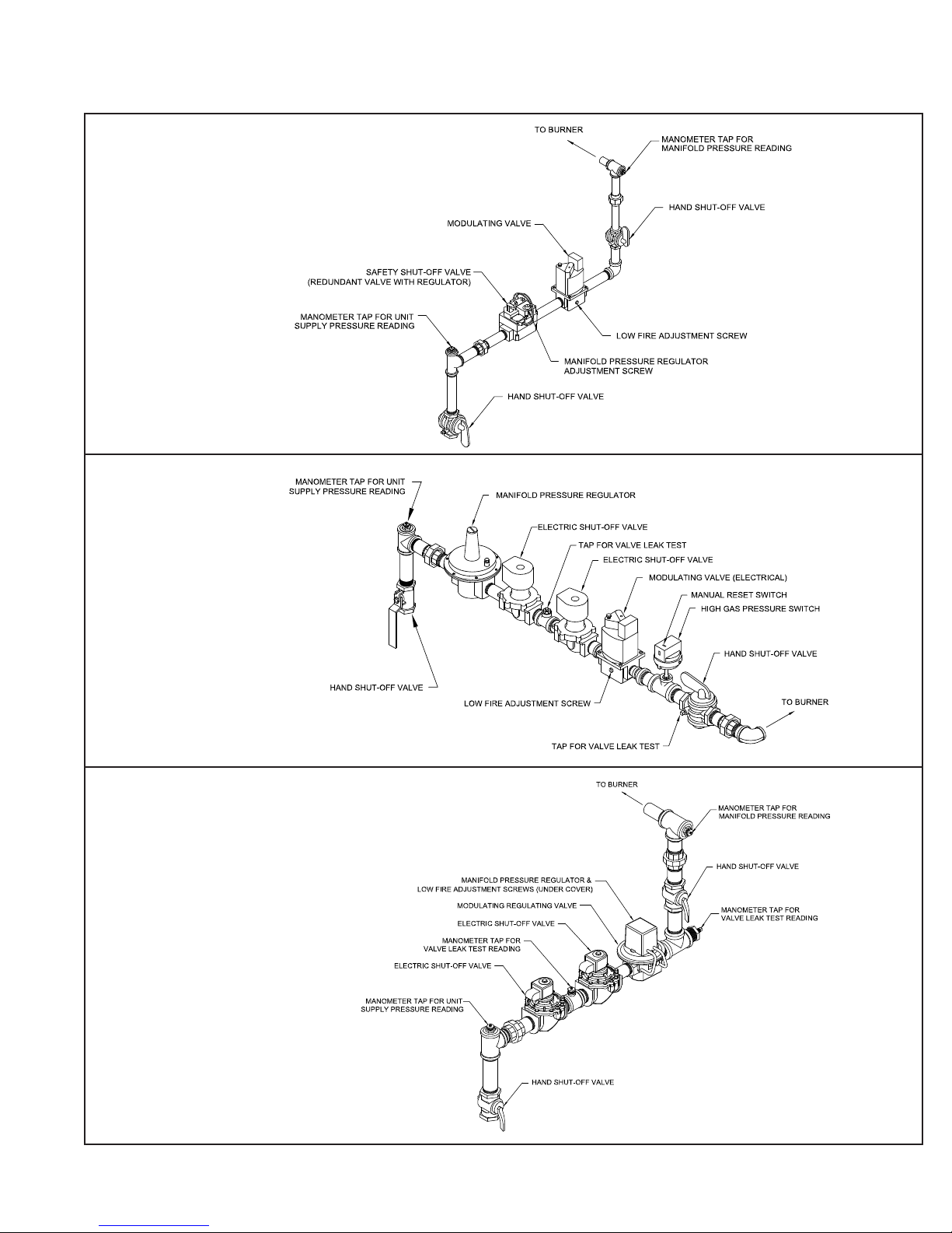
REFERENCE
GAS TRAIN DRAWINGS
Horizontal Mount
< 400 MBH
CSA Certified
Vertical Mount
> 400 MBH
Low Pressure
CSA Certified
Horizontal Mount
> 400 MBH
High Pressure
CSA Certified
M-Series Technical Manual 49 Cambridge Engineering, Inc.
Page 52

BLOWER CLEANING
The blower wheel should be examined for accumulation
of dust on the blades. These surfaces must be kept clean.
Dirt accumulation will result in significant air flow
reduction and/or possible imbalance of the blower wheel.
Prolonged imbalance CAN result in catastrophic failure
of the blower wheel and other related components.
BURNER CLEANING
The Cambridge Engineering burner is for the most part
self-cleaning. However, if the application is extremely
dirty or dusty, it may become necessary to periodically
clean the burner. Remove and clean the burner in accordance with the following recommended procedures.
to the coil is correct, sluggish valve operation, excessive
noise, or leakage will indicate that cleaning is required.
Refer to step 8, Gas Valve Leak Check, of the Start-up
Procedures (see page 32).
mWARNING:
In the extreme case, faulty valve operation will
occur and the valve may fail to open or fully close.
IMPORTANT
It is not necessary to remove the valve from the gas
train for cleaning.
1. Turn the heater disconnect switch off. Close the manual gas supply shut-off valve.
2. Loosen the union in the gas train.
CAUTION:
The igniter is made of silicon carbide material and
should be handled with care to avoid breakage.
3. Disconnect the ignition cable from the burner and then
remove the flame rod and the igniter.
4. Examine the flame rod ceramic for cracks and replace
if necessary. Clean the flame rod element with emery
cloth to remove oxidation.
5. Remove the fasteners that secure the burner to the
housing. The burner will then be free to slide out.
mCAUTION:
Be sure to take necessary safety precautions (such
as wearing eye protection, etc.) before attempting
this step.
mWARNING:
To prevent the possibility of severe personal injury or property damage, turn off electrical power,
close the upstream manual gas valve, depressurize the valve, extinguish all open flames and
avoid any type of sparking or ignition. Vent hazardous or combustible fumes to a safe area before
servicing the valve.
6. Clean the burner by back-flushing using high pressure
air (40-80 PSI). Continue back-flushing until dust particles are completely expelled from the burner.
7. Re-install the burner using the above steps in reverse
order.
GAS VALVE CLEANING
All solenoid valves should be cleaned periodically.
The time between cleanings will vary depending on the
medium and service conditions. In general, if the voltage
Cambridge Engineering, Inc. 50 M-Series Technical Manual
Page 53

ASCO GAS VALVES: SERIES 8214
Disassemble the valve (See page 62) and clean all parts
as follows:
IMPORTANT
If parts are worn or damaged, install a complete ASCO
Rebuild Kit.
mWARNING:
To prevent the possibility of severe personal injury or
property damage, check the valve for proper operation
before returning to service. Also perform a gas valve
leak check and gas train leak check in accordance with
steps 8 and 9 of the Start-up Procedures (see page 32).
1. Remove the solenoid enclosure.
2. Remove the bonnet screws, valve bonnet, bonnet gasket, core/diaphragm sub-assembly and body gasket.
3. All parts are now accessible to clean or replace.
4. Lubricate the bonnet gasket and body gasket with a
light coat of Dow Corning
equivalent high-grade silicone fluid.
5. Apply a light coat of RemGrit TFL 50® Dry Lubricant
to: the valve seat; the valve body surface where diaphragm assembly contacts the valve body and body
gasket; and internal surface of the valve bonnet where
the diaphragm assembly contacts the bonnet when the
valve is in the energized (open) position.
IMPORTANT:
If the valve has been disassembled for inspection and
cleaning only and a Rebuild Kit is not being installed,
lubricate the following with RemGrit TFL 50® Dry
Lubricant:
®
200 Fluid lubricant or an
ORDERING INFORMATION FOR ASCO
REBUILD KITS
Parts marked with an asterisk (*) in the exploded views
are supplied in Rebuild Kits.
When ordering Rebuild Kits for ASCO valves, order the
Rebuild Kit number stamped on the valve nameplate. If
the number of the kit is not visible, order by indicating
the number of kits required, and the Catalog Number
and Serial Number of the valve(s) for which they are
intended.
GAS TRAIN LEAK CHECK
Periodically check the gas control assembly, internal
and external piping for leaks. Refer to step 9, Gas Train
Leak Check, of the Start-up Procedures (see page 32).
All relief vents on the gas controls should be checked for
blockage (gas pressure regulators and pressure switches).
• Diaphragm assembly on both sides
• Main disc at base of core/diaphragm sub-assembly
• Pilot disc at base of core assembly
mCAUTION:
Do not distort the hanger spring between the core
assembly and the diaphragm assembly when
lubricating the pilot disc.
6. Replace the body gasket and the core/diaphragm subassembly with the closing spring attached. Locate
the bleed hole in the core/diaphragm sub-assembly
approximately 30˚ CCW from the valve inlet.
7. Replace the valve bonnet and the bonnet screws (6).
Torque the screws in a crisscross manner to 100 ± 10
in-lbs. Replace the solenoid and make the electrical
hookup.
M-Series Technical Manual 51 Cambridge Engineering, Inc.
Page 54
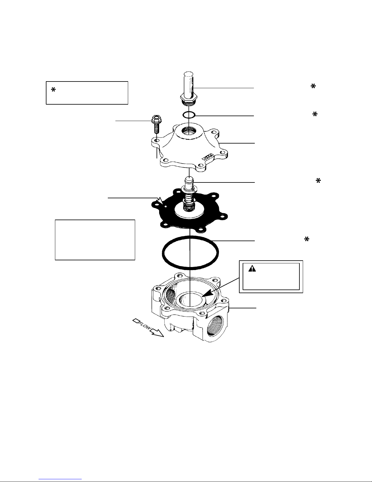
Indicates parts supplied
in ASCO Rebuild Kit.
SOLENOID BASE
SUBASSEMBLY
BONNET SCREW
BLEED HOLE
Locate bleed hole in
core/diaphragm sub---
assembly approximately
30° from valve inlet
BONNET GASKET
VALVE BONNET
CORE/DIAPHRAGM
SUBASSEMBLY
BODY GASKET
CAUTION
Do not damage
valve seat
VALVE BODY
Disassembled View of ASCO Valve
Cambridge Engineering, Inc. 52 M-Series Technical Manual
Page 55

FILTERS
Filters may be installed in the V-bank filter section or in
the intake of the rainhoods. These may be of the disposable or permanent type. Filters are removed and replaced
from the V-bank filter section by opening the filter
access door. Filters are removed from the rainhood by
removing the retainer from the end of the rainhood. To
remove the retainer, remove the shipping screws from
the ends of the retainer, then pull the retainer back and
downward from the rainhood.
Permanent Filters are 2" thick washable, metal mesh
filters that may be installed in the rainhoods or in the
V-bank filter section.
Disposable Filters may be one of two types:
1. Pleated panel filters are 2" thick filters which slide
into tracks provided in the V-Bank filter section only.
(Do not use this type of filter in the rainhoods because
of moisture exposure.)
2. Continuous filters are constructed of a two-stage
media. The white side faces into the airstream and
the orange side faces the exiting air. Internal frames
ensure rigidity, while the continuous media eliminates
gaps between filters and effectively seals against the
filter tracks. These filters are unaffected by moisture
and may be installed in the rainhoods or in the V-bank
filter section.
Disposable pleated panel filters are replaced when they
become dirty. Replace the filter with the same size of
filter which is removed from the filter section. Note the
airflow markings on the filter.
Disposable continuous filters are replaced when they
become dirty. Continuous filters are manufactured one
panel wide by 24 panels long. (eg., 16" x 600" filters
consists of 24-16" x 25" panels and 25" x 384" filters
consist of 24-25" x 16" panels.) Cut these filters between
panels to select the continuous length required for the filter track. If four 16" x 25" panels are required for a filter
track, simply cut a four-panel length. Install the filters
with the white side toward the air inlet.
CLEANING AND REPLACEMENT
Shut down the heater and turn off the blower before servicing the filters. Remove the filters from the rainhood
or filter section. Handle carefully to prevent debris from
being dislodged from the filter into the heater.
Permanent filters can be cleaned using a stream of
water or soap and water. Back flush the filters until the
water comes out clean. If soap is used, ensure that all
soap is rinsed out of the filter. Visually inspect the filter
to ensure that it is clean. Allow to dry before returning to
service.
M-Series Technical Manual 53 Cambridge Engineering, Inc.
Page 56
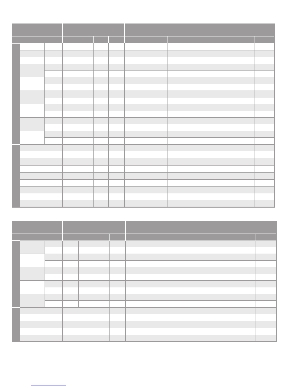
Filters for Horizontal Mount
Filter Type
Size (inches) 16x20 16x25 20x20 20x25 16x480 16x600 20x384 20x480 20x600 25x384 25x480
M110
M112
M115
M118
M120
M125
Rainhood
M130
M136
M140
Single 3 3 (1x3)
Single 3 3 (1x3)
Single 4 2 4 (2x2) 2 (1x2)
Upper 2 2 2 (1x2) 2 (1x2)
Lower 2 2 2 (1x2) 2 (1x2)
Upper 6 3 6 (2x3) 3 (1x3)
Lower 4 2 4 (2x2) 2 (1x2)
Upper 12 12 (4x3)
Lower 8 8 (4x2)
Upper 12 4 12 (3x4) 4 (1x4)
Lower 9 3 9 (3x3) 3 (1x3)
Upper 15 5 15 (3x5) 5 (1x5)
Lower 12 4 12 (3x4) 4 (1x4)
Upper 5 25 5 (1x5) 25 (5x5)
Lower 4 20 4 (1x4) 20 (5x4)
M110
M112
M115
M118
M120
M125
Filter Section
M130
M136
M140
Permanent or
Disposable Panel
3 3 (3x1)
3 3 (3x1)
6 6 (3x2)
8 8 (4x2)
10 10 (5x2)
20 20 (5x4)
24 24 (6x4)
28 28 (7x4)
56 56 (8x7)
Continuous*
Filters for Vertical Mount
Filter Type
Size (inches) 16x20 16x25 20x20 20x25 16x480 16x600 20x384 20x480 20x600 25x384 25x480
M118
M120
M125
Rainhood
M130
M136
Upper 8 8 (4x2)
Lower 4 4 (4x1)
Upper 2 4 2 (1x2) 4 (2x2)
Lower 2 4 2 (1x2) 4 (2x2)
Upper 9 9 (3x3)
Lower 6 6 (3x2)
Upper 3 9 3 (1x3) 9 (3x3)
Lower 3 9 3 (1x3) 9 (3x3)
Upper 15 15 (5x3)
Lower 15 15 (5x3)
M118
M120
M125
M130
Filter Section
M136
* Continuous filters are manufactured in lengths of 24 panels. Cut filter panels like chain links. For example, 6 (2x3) means cut
2 rows x 3 panels long for total of 6 panels of this type. Cut only between filter panels.
Permanent or
Disposable Panel
9 9 (3x3)
16 16 (4x4)
15 15 (5x3)
36 36 (6x6)
30 30 (6x5)
Continuous*
Cambridge Engineering, Inc. 54 M-Series Technical Manual
Page 57
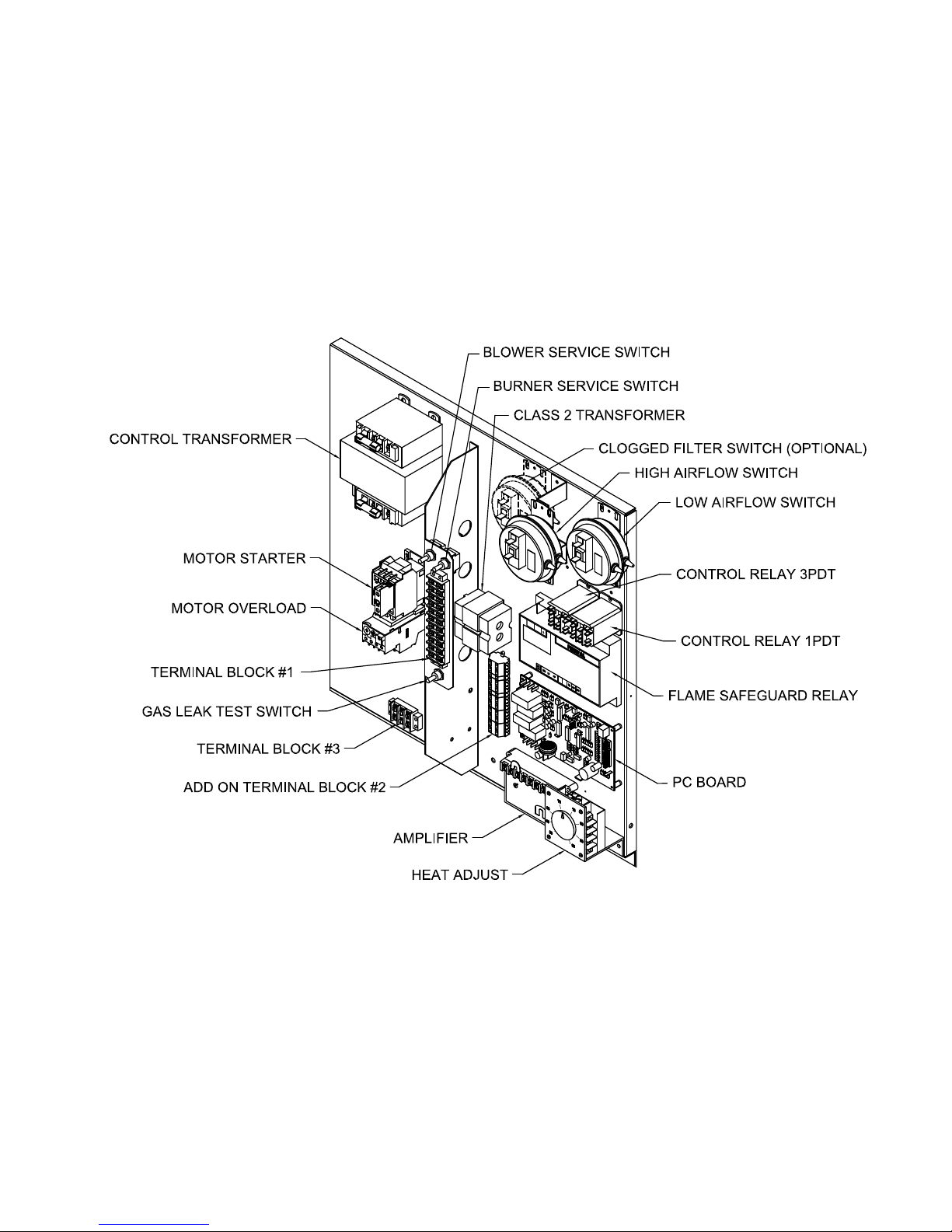
REFERENCE
ELECTRICAL CONTROL ENCLOSURE ISOMETRIC DRAWING
M110 - M115
M-Series Technical Manual 55 Cambridge Engineering, Inc.
Page 58
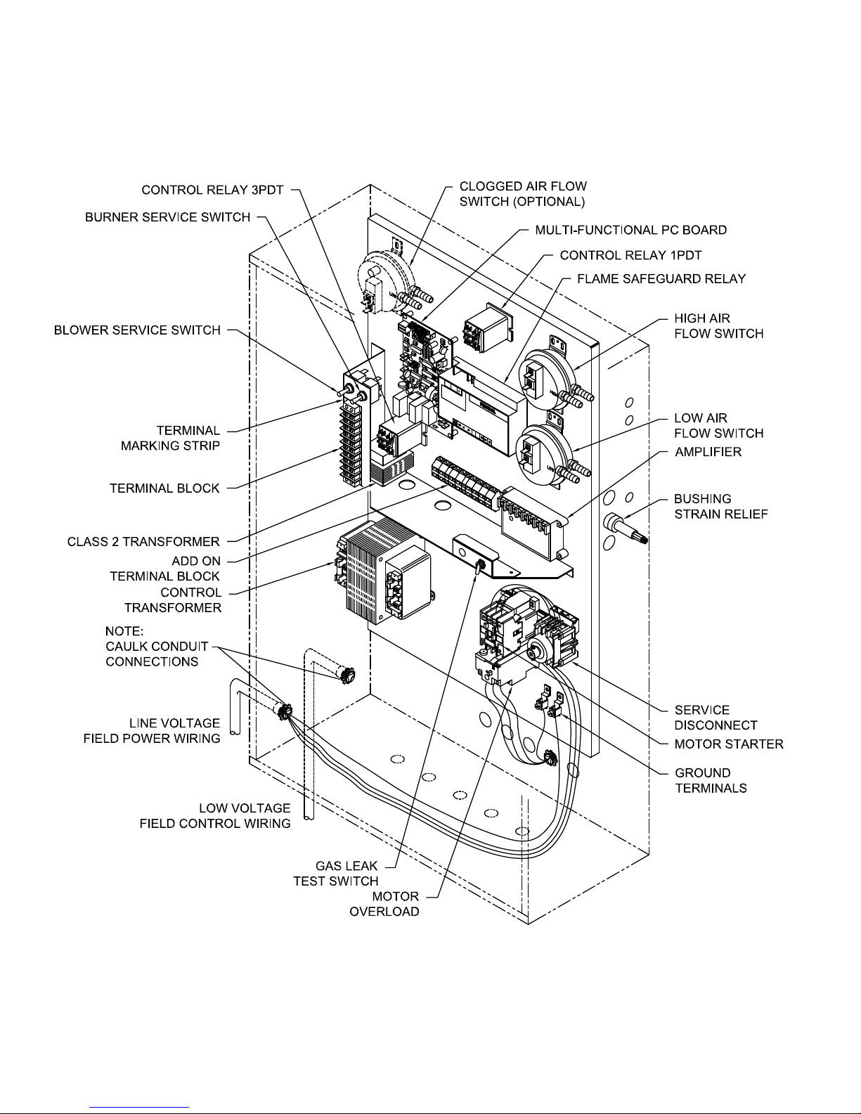
REFERENCE
ELECTRICAL CONTROL ENCLOSURE ISOMETRIC DRAWING
M118 - M136
Cambridge Engineering, Inc. 56 M-Series Technical Manual
Page 59
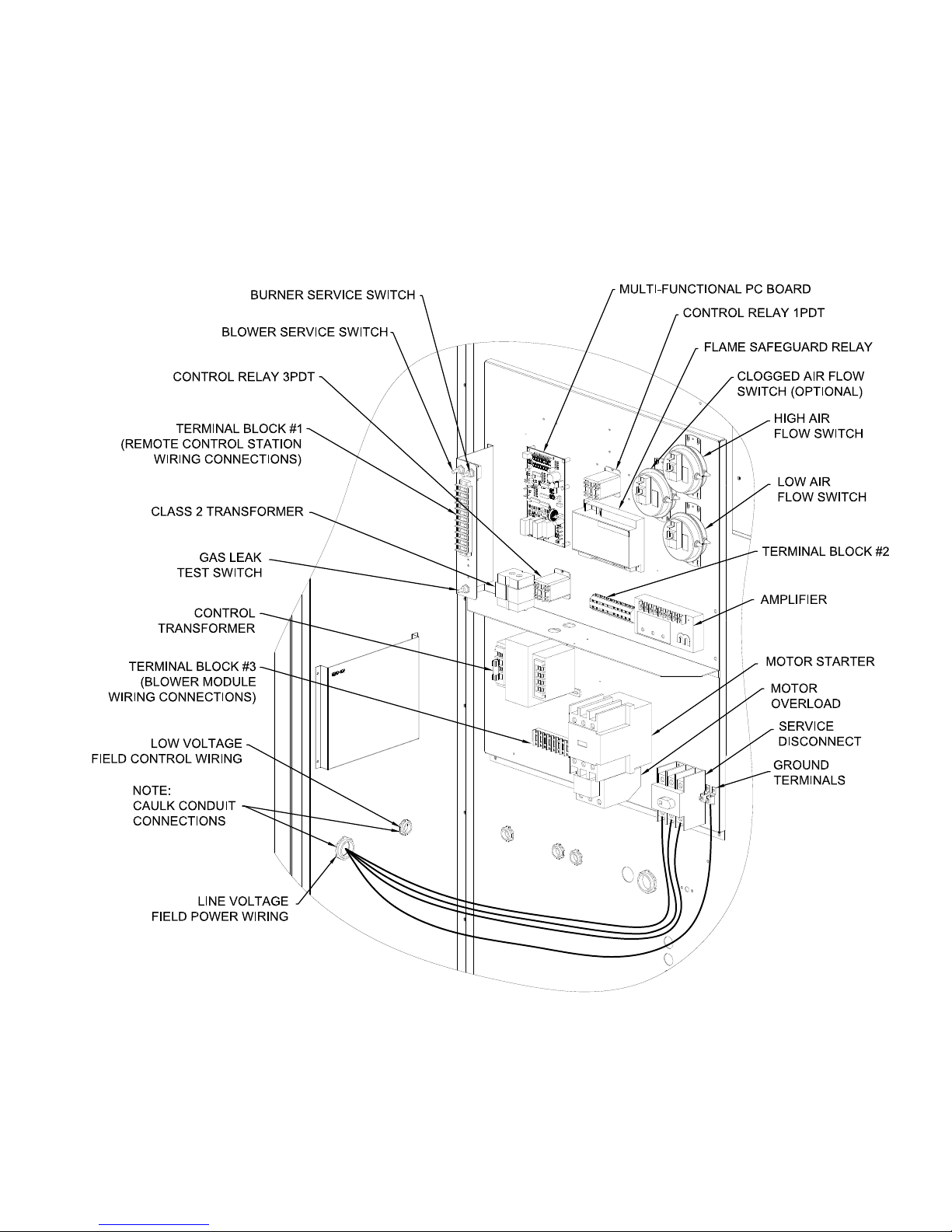
ELECTRICAL CONTROL ENCLOSURE
ISOMETRIC DRAWING
M140
M-Series Technical Manual 57 Cambridge Engineering, Inc.
Page 60
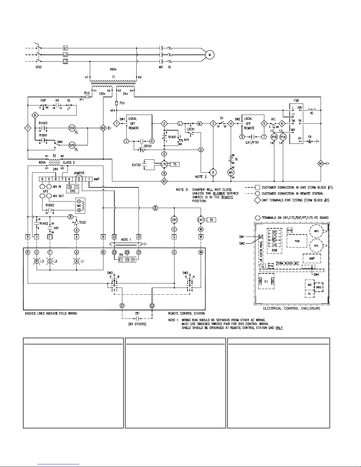
REFERENCE
ELECTRICAL WIRING DIAGRAMS
Series 14
SYMBOL DESCRIPTION
AFL Air Flow Switch - Low
AFH Air Flow Switch - High
AMP Amplifier Solid State
AX1 Auxiliary Contact
AX Auxiliary Contact
CR1 Control Relay
D & D1 Damper Motor & End Switch
DISC Service Disconnect Non - Fused
DTS Discharge Temperature Sensor
EAT Entering Air Thermostat
EFI Exhaust Fan Interlock
FR Flame Rod
FSR Flame Safeguard Relay (HSI)
Cambridge Engineering, Inc. 58 M-Series Technical Manual
SYMBOL DESCRIPTION
FU1 Fuse 24 Volt Control
FU2 Fuse 120 Volt Control
HGP High Gas Pressure Switch
HL High Limit
IG Ignitor
L1 Light - Alarm
L2 Light - Fan
L3 Light - Heat
LFS Low Fire Start
LTC Low Temperature Cutout
M Motor
MS Motor Starter
MV Modulating Valve
SYMBOL DESCRIPTION
OL Overload Relay
PT Purge Timer
RA Remote Adjust
R1A&R1B Relay Gas Valve
SOV Shut-Off Valve - Gas
SSV Safety Shut-Off Valve - Gas
SW1 Service Switch - Fan
SW2 Service Switch - Heat
SW3 Switch - Fan/Off/Heat
SW4 Switch - SOV Leak Test
T1 Multi-Tap Transformer (24&120 Volt)
T2 Class 2 Transformer (24 Volt)
TS Temperature Sensor
Page 61
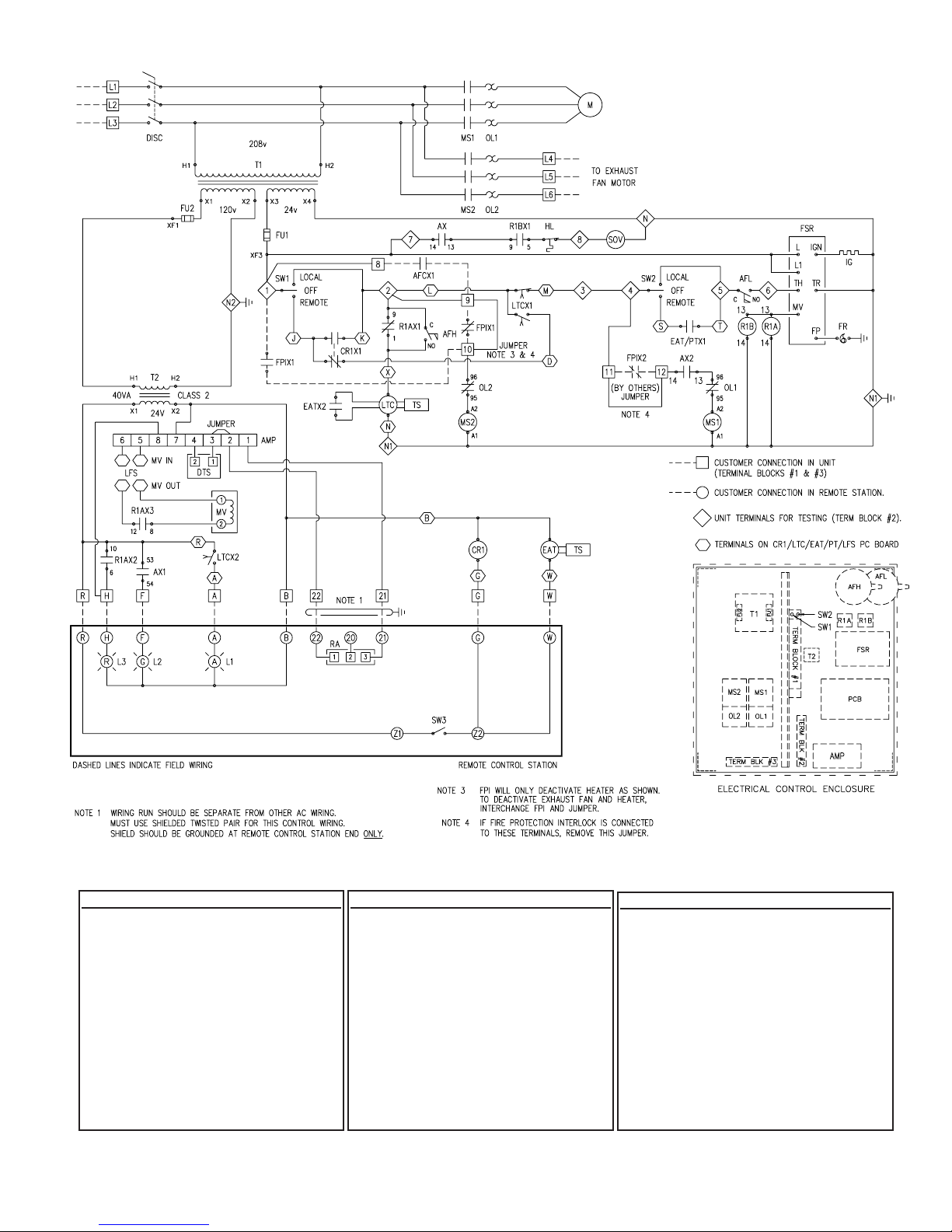
Series 14
Kitchen Ventilation System
SYMBOL DESCRIPTION
AFL Air Flow Switch - Low
AFH Air Flow Switch - High
AMP Amplifier Solid State
AX Auxiliary Contact
AX1 Auxiliary Contact
AX2 Auxiliary Contact
CR1 Control Relay
DISC Service Disconnect Non - Fused
DTS Discharge Temperature Sensor
EAT Entering Air Thermostat
FPI Fire Protection Interlock
FR Flame Rod
FSR Flame Safeguard Relay (HSI)
M-Series Technical Manual 59 Cambridge Engineering, Inc.
SYMBOL DESCRIPTION
FU1 Fuse 24 Volt Control
FU2 Fuse 120 Volt Control
HL High Limit
IG Ignitor
L1 Light - Alarm
L2 Light - Fan
L3 Light - Heat
LFS Low Fire Start
LTC Low Temperature Cutout
M Motor - Supply Fan
MS1 Motor Starter - Supply Fan
MS2 Motor Starter - Exhaust Fan
MV Modulating Valve
SYMBOL DESCRIPTION
OL1 Overload Relay - Supply Fan
OL2 Overload Relay - Exhaust Fan
PT Purge Timer
RA Remote Heat Adjust
R1A&R1B Relay-Gas Valve
SOV Shut-Off Valve - Gas
SW1 Service Switch - Fan
SW2 Service Switch - Heat
SW3 Switch - Off/On
T1 Multi-Tap Transformer (24&120 Volt)
T2 Class 2 Transformer (24 Volt)
TS Temperature Sensor
Page 62
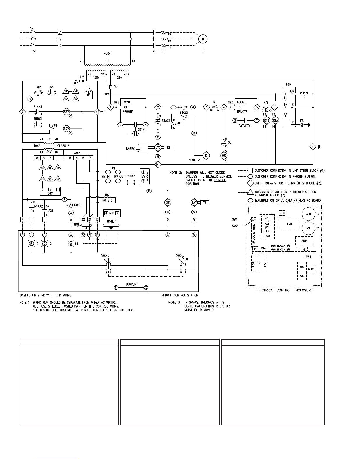
Series 44
M140
SYMBOL DESCRIPTION
AFL Air Flow Switch - Low
AFH Air Flow Switch - High
AMP Amplifier Solid State
AX1 Auxiliary Contact
AX Auxiliary Contact
CR1 Control Relay
D & D1 Damper Motor & End Switch
DISC Service Disconnect Non - Fused
DTS Discharge Temperature Sensor
EAT Entering Air Thermostat
FR Flame Rod
FSR Flame Safeguard Relay (HSI)
FU1 Fuse 24 Volt Control
Cambridge Engineering, Inc. 60 M-Series Technical Manual
SYMBOL DESCRIPTION
FU2 Fuse - 120 Volt Control
HGP High Gas Pressure Switch
HL High Limit
IG Ignitor
L1 Light - Alarm
L2 Light - Fan
L3 Light - Heat
LFS Low Fire Start
LTC Low Temperature Cutout
M Motor
MS Motor Starter
MV Modulating Valve
OL Overload Relay
SYMBOL DESCRIPTION
PT Purge Timer
R1A&R1B Relay Gas Valve
RC Resistor - Calibration
SOV Shut-Off Valve - Gas
SSV Safety Shut-Off Valve - Gas
STS Space Temperature Selector
SW1 Service Switch - Fan
SW2 Service Switch - Heat
SW3 Switch - Fan/Off/Heat
SW4 Switch - SOV Leak Test
T1 Multi-Tap Transformer (24&120 Volt)
T2 Class 2 Transformer (24 Volt)
TS Temperature Sensor
Page 63
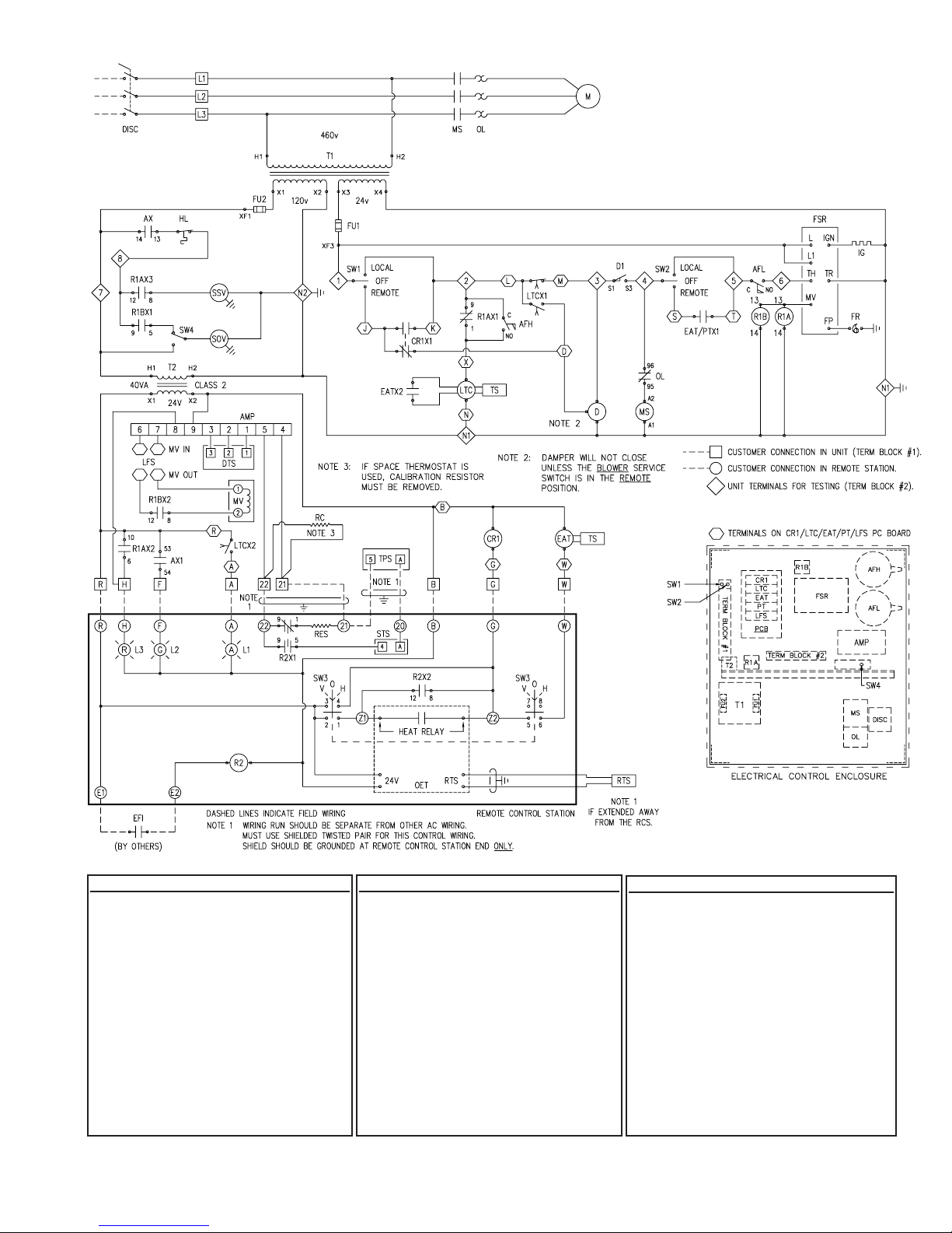
Series 44
Tamperproof Controls
Operating Thermostat
SYMBOL DESCRIPTION
AFL Air Flow Switch - Low
AFH Air Flow Switch - High
AMP Amplifier Solid State
AX1 Auxiliary Contact
AX Auxiliary Contact
CR1 Control Relay
D & D1 Damper Motor & End Switch
DISC Service Disconnect Non - Fused
DTS Discharge Temperature Sensor
EAT Entering Air Thermostat
EFI Exhaust Fan Interlock
FR Flame Rod
FSR Flame Safeguard Relay (HSI)
FU1 Fuse 24 Volt Control
FU2 Fuse 120 Volt Control
M-Series Technical Manual 61 Cambridge Engineering, Inc.
SYMBOL DESCRIPTION
HL High Limit
IG Ignitor
L1 Light - Alarm
L2 Light - Fan
L3 Light - Heat
LFS Low Fire Start
LTC Low Temperature Cutout
M Motor
MS Motor Starter
MV Modulating Valve
OET Operating Electronic Thermostat
OL Overload Relay
PT Purge Timer
R1A&R1B Relay Gas Valve
R2 Relay - Intermittent/Continuous
SYMBOL DESCRIPTION
RC Resistor - Calibration
RTS Remote Temperature Sensor
SOV Shut-Off Valve - Gas
SSV Safety Shut-Off Valve - Gas
STS Space Temperature Selector
SW1 Service Switch - Fan
SW2 Service Switch - Heat
SW3 Switch - Fan/Off/Heat
SW4 Switch - SOV Leak Test
T1 Multi-Tap Transformer (24&120 Volt)
T2 Class 2 Transformer (24 Volt)
TPS Tamper Proof Space Sensor
TS Temperature Sensor
Page 64
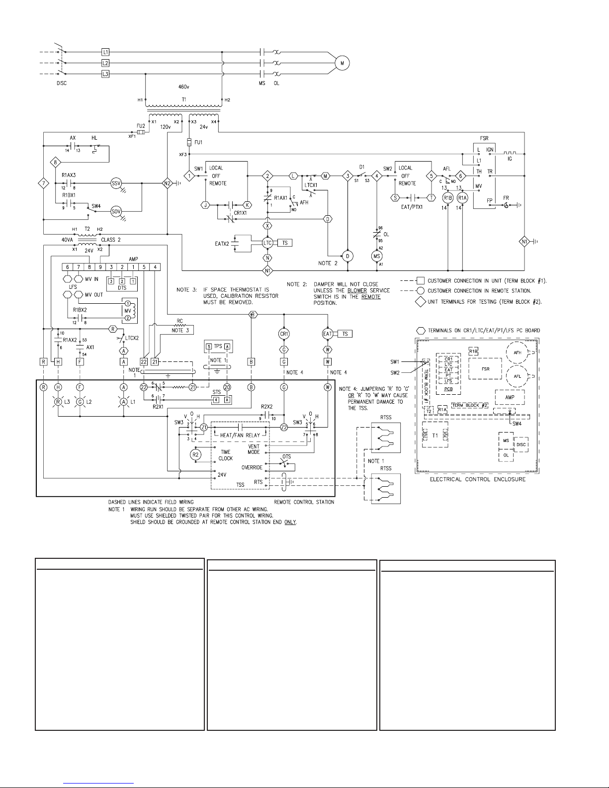
Series 44
Temperature Setback System
Temperature Averaging System
Tamperproof Controls
SYMBOL DESCRIPTION
AFL Air Flow Switch - Low
AFH Air Flow Switch - High
AMP Amplifier Solid State
AX1 Auxiliary Contact
AX Auxiliary Contact
CR1 Control Relay
D & D1 Damper Motor & End Switch
DISC Service Disconnect Non - Fused
DTS Discharge Temperature Sensor
EAT Entering Air Thermostat
FR Flame Rod
FSR Flame Safeguard Relay (HSI)
FU1 Fuse 24 Volt Control
FU2 Fuse 120 Volt Control
Cambridge Engineering, Inc. 62 M-Series Technical Manual
SYMBOL DESCRIPTION
HL High Limit
IG Ignitor
L1 Light - Alarm
L2 Light - Fan
L3 Light - Heat
LFS Low Fire Start
LTC Low Temperature Cutout
M Motor
MS Motor Starter
MV Modulating Valve
OTS Override Timer Switch
OL Overload Relay
PT Purge Timer
R1A&R1B Relay - Gas Valve
SYMBOL DESCRIPTION
R2 Relay - Intermittent/Continuous
RC Resistor - Calibration
RTS Remote Temperature Sensor
SOV Shut-Off Valve - Gas
SSV Safety Shut-Off Valve - Gas
STS Space Temperature Selector
SW1 Service Switch - Fan
SW2 Service Switch - Heat
SW3 Switch - Fan/Off/Heat
SW4 Switch - SOV Leak Test
T1 Multi-Tap Transformer (24&120 Volt)
T2 Class 2 Transformer (24 Volt)
TPS Tamper Proof Space Sensor
TS Temperature Sensor
TSS Temperature Setback System
Page 65
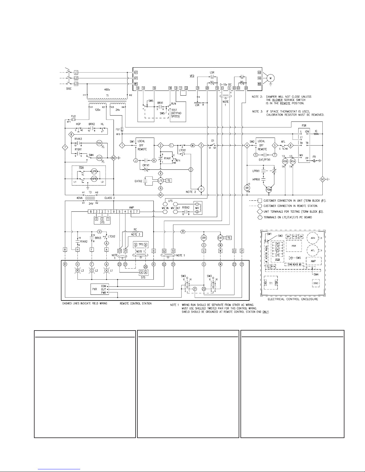
Series 44
Tamperproof Controls
Variable Frequency Drive
Room Pressure Controller
SYMBOL DESCRIPTION
AFL Air Flow Switch - Low
AFH Air Flow Switch - High
AMP Amplifier Solid State
AX1 Auxiliary Contact
AX Auxiliary Contact
BR Relay - Blower
CR1 Control Relay
D & D1 Damper Motor & End Switch
DISC Service Disconnect Non - Fused
DTS Discharge Temperature Sensor
EAT Entering Air Thermostat
FR Flame Rod
FSR Flame Safeguard Relay (HSI)
FU1 Fuse 24 Volt Control
FU2 Fuse 120 Volt Control
HGP High Gas Pressure Switch
M-Series Technical Manual 63 Cambridge Engineering, Inc.
SYMBOL DESCRIPTION
HL High Limit
HPR Relay - High Pressure
IG Ignitor
L1 Light - Alarm
L2 Light - Fan
L3 Light - Heat
LFS Low Fire Start
LPR Relay - Low Pressure
LSK Low Speed Kit
LSR Relay - Low Speed
LTC Low Temperature Cutout
M Motor
MV Modulating Valve
PDA Profile Damper Adjustment
PDM Profile Damper Motor
PT Purge Timer
SYMBOL DESCRIPTION
PXR Pressure Transducer
R1A&R1B Relay Gas Valve
SOV Shut-Off Valve - Gas
SSV Safety Shut-Off Valve - Gas
STS Space Temperature Selector
SW1 Service Switch - Fan
SW2 Service Switch - Heat
SW3 Switch - Fan/Off/Heat
SW4 Switch - SOV Leak Test
SW5 Service Switch - Run/Test
T1 Multi-Tap Transformer (24&120 Volt)
T3 Class 2 Transformer (24 Volt)
TPS Tamper Proof Space Sensor
TS Temperature Sensor
VFD Variable Frequency Drive
Page 66

CONNECTION DIAGRAM
(Typical)
PROVIDED ON MAXITROL
SERIES 44 SYSTEMS AND
SERIES 14 SYSTEMS WITH
OPTIONAL RHA CONTROL
FOR MAXITROL SERIES 44 SYSTEMS AND SERIES 14
SYSTEMS WITH RHA CONTROL
USE 2 WIRE SHIELDED TWISTED-PAIR
18 AWG MINIMUM
RUN SEPARATE FROM ALL OTHER AC WIRING
GROUND SHIELD AT REMOTE CONTROL STATION ONLY
Cambridge Engineering, Inc. 64 M-Series Technical Manual
Page 67
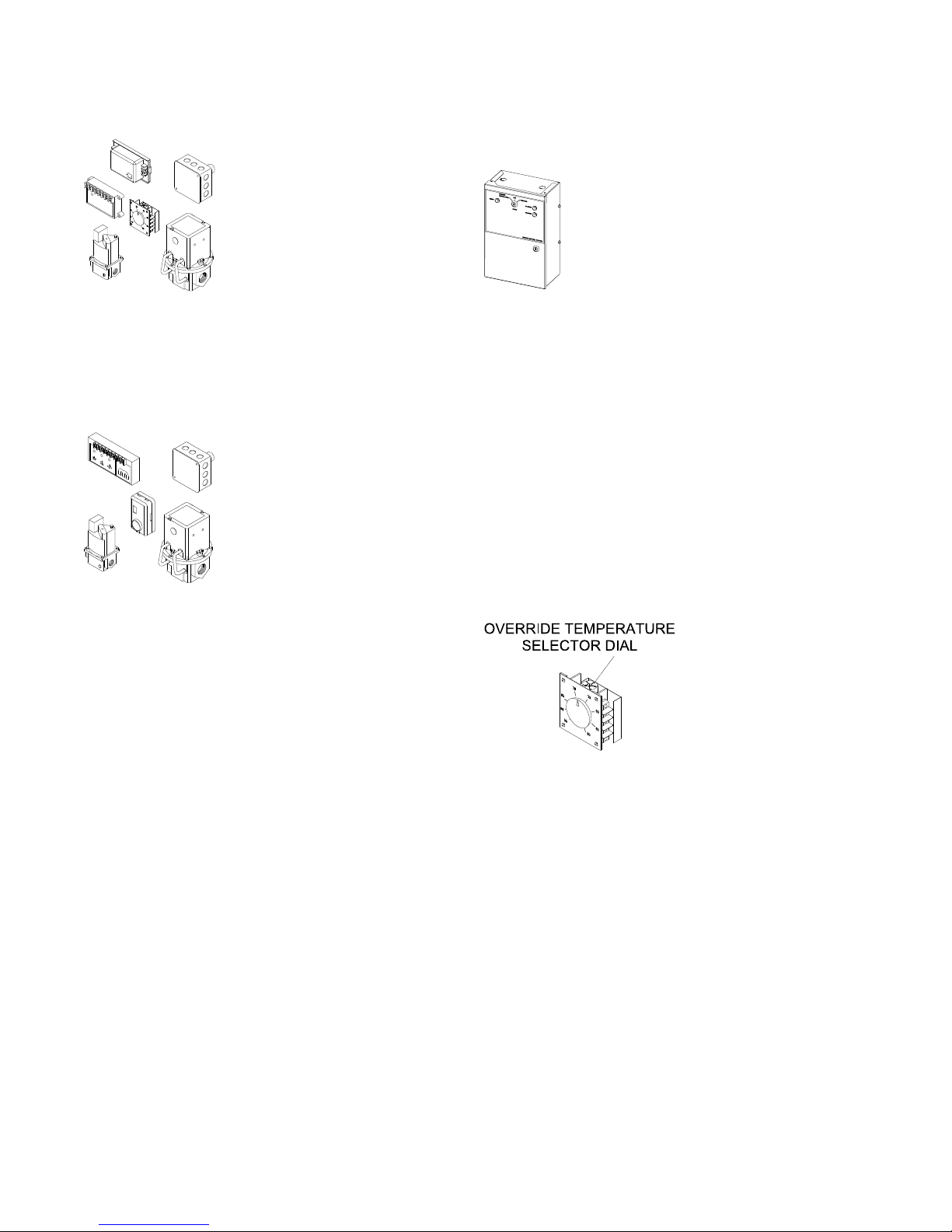
GAS CONTROL SYSTEMS
Maxitrol Series 14
The Maxitrol Series 14 controls
electronically modulate the burner
input to maintain a selected discharge temperature. The discharge
temperature is set on the amplifier
(AD1014) between 55°F and 90°F
with the standard controls. As an
option, the discharge temperature
can be set on a Remote Heat Adjust (TD114) control
between 55°F and 130°F. The Remote Heat Adjust control can be mounted in the heater control enclosure or in
the Remote Control Station.
Maxitrol Series 44
The Maxitrol Series 44 controls
electronically modulate the burner
input to maintain a constant space
temperature by increasing or
decreasing the discharge temperature. The Space Temperature
Selector (T244A) is set to main-
tain the space temperature of the
heated space by controlling the heater output between the
MIN and MAX setting on the amplifier. The MIN dial
setting determines the minimum discharge temperature
the heater will deliver (40°F to 80°F). The MAX dial setting determines the maximum discharge temperature the
heater will deliver (80°F to 140°F)
Intermittent/Continuous Control
The Intermittent/Continuous Control allows the burner
input to be modulated to be operated continuously at
modulating discharge temperature for make-up air (see
Maxitrol 44 above) or operated intermittently based
on a thermostat at maximum discharge temperature for
space heating.
Requires Maxitrol 44 controls and a signal to switch
between modes (Exhaust Fan Interlock, Temperature
Setback System, Manual Make-Up Air Switch, etc.)
REMOTE CONTROL STATION COMPONENTS
Remote Control Station
The Remote Control Station is a lockable
NEMA 1 enclosure (9" wide x 14" high x
5" deep) equipped with a three position
key lock selector switch (Summer
Ventilation – Off – Heating) and indicating lights for blower operation (green),
burner operation (red), and reset (amber).
An auxiliary contact wired between terminals Z1 and
Z2 is required to control heater operation in the heating mode. This can be accomplished by an Exhaust
Fan Interlock, a Manual Make-up Air Switch, an
Operating Electronic Thermostat, etc.
IMPORTANT
A number of the components listed below can be
combined to yield a custom Remote Control Station
to address a wide variety of applications.
Maxitrol Series 14 Remote Heat
Adjustment Dial
The adjustment dial on
the remote heat adjust
(TD114) is either mounted on the exterior of the
door of the Remote
Control Station or
mounted inside the
Remote Control Station
for tamperproof applications. The remote heat adjustment control permits manual adjustment of the discharge temperature from 55˚F to 90˚F. The override temperature selector dial, visible from the top of the remote
heat adjustment control, increases the discharge temperature above the setting on the dial face by the increment selected (10˚F to 40°F) when a jumper or switch
contact is provided across terminals 20 and 22.
Maxitrol 14 Space Temperature Override
The Maxitrol Series 14 with Space Thermostat control
system uses the Maxitrol Series 14 controls described
above along with an electronic space thermostat switch
contact to automatically increase the discharge temperature.
M-Series Technical Manual 65 Cambridge Engineering, Inc.
Page 68

Maxitrol Series 44 / Tamperproof
The Maxitrol Series 44 / Tamperproof controls
function identically to the Maxitrol Series 44 controls (see gas control system) except the space
temperature selector (T244A) is replaced with
two devices. The adjustable portion, the space
temperature selector (TD244A), is mounted inside
the Remote Control Station, and the non-adjust-
able
(tamperproof) space sensor (TS244A) is mounted in the
space being heated.
Maxitrol Series 44 / Hazardous Area
The Maxitrol Series 44 / Hazardous Area is the same as the
Maxitrol Series 44 / Tamperproof, except the space sensor
(TS244A) is replaced by a space sensor with epoxy coated
circuitry (ES225A). The standard Remote Control Station
is not suitable for hazardous areas and would need to be
mounted outside of the hazardous area.
Operating Electronic Thermostat
The operating electronic thermostat is
wired between terminals Z1 and Z2 to
control heater ON/OFF operation in the
heating mode (see pages 65).
Non-Adjustable Thermostat
The non-adjustable thermostat is a fixed temperature,
solid state, epoxy sealed thermostat with a specified
temperature setpoint, either: 41°F, 50°F, 55°F, 60°F, or
65°F. It is wired between terminals Z1 and Z2.
Temperature Setback System
The temperature setback system is a combination seven-day programmable timer
with
independent programs for summer ventilation/heating modes and integral electronic
thermostat with separate selectable day/
night setback temperatures (see page 67).
The thermostat contact is wired between
Z1 and Z2.
Manual Make-Up Air Switch
A manual make-up air toggle switch is used to manually turn the heater on and off. It is either mounted on
the exterior of the door of the Remote Control Station or
mounted inside the Remote Control Station for tamperproof applications.
Exhaust Fan Interlock
An exhaust fan interlock is used to interlock the makeup air heater as a slave to an exhaust fan. Terminals are
provided in the Remote Control Station for wiring of dry
contacts (by others).
INDIVIDUAL HEATER COMPONENT
DESCRIPTIONS
AIR FLOW SWITCH (High and Low)
The air flow switches sense the pressure drop across the burner profile
plate. They are factory set and not
adjustable. They are designed to prevent burner operation if the pressure
drop across the burner drops below
0.40
inch WC or increases above
0.85
inch WC for natural gas applications or below
0.60
inch WC or above 1.12 inches WC for LP gas
applications.
AMPLIFIER
The amplifier creates a voltage output
to drive an electronic proportioning gas
valve to maintain the selected discharge
temperature (Maxitrol Series 14) or
space temperature (Maxitrol Series 44).
On Maxitrol Series 14 control systems,
the discharge temperature is set either
on the amplifier (AD1014) or the
Remote Heat Adjust (TD114). On Maxitrol Series 44
control systems, the range of the discharge temperature
is set on the amplifier (A1044), but the space temperature selector controls when more or less heat is required.
Clogged Filter Light
The clogged filter light is an alarm light mounted in the
Remote Control Station to indicate a clogged filter condition. Includes an adjustable pressure switch mounted in
the make-up air heater control enclosure to monitor the
pressure drop across the filters.
Cambridge Engineering, Inc. 66 M-Series Technical Manual
CONVENIENCE OUTLET
A convenient 115 volt GFI duplex receptacle is provided
inside the heater’s electrical enclosure. The electrical
supply source for this device can be either the heater’s
control power transformer (5 amps max.) or a separate
outside source (15 amps max.).
Page 69
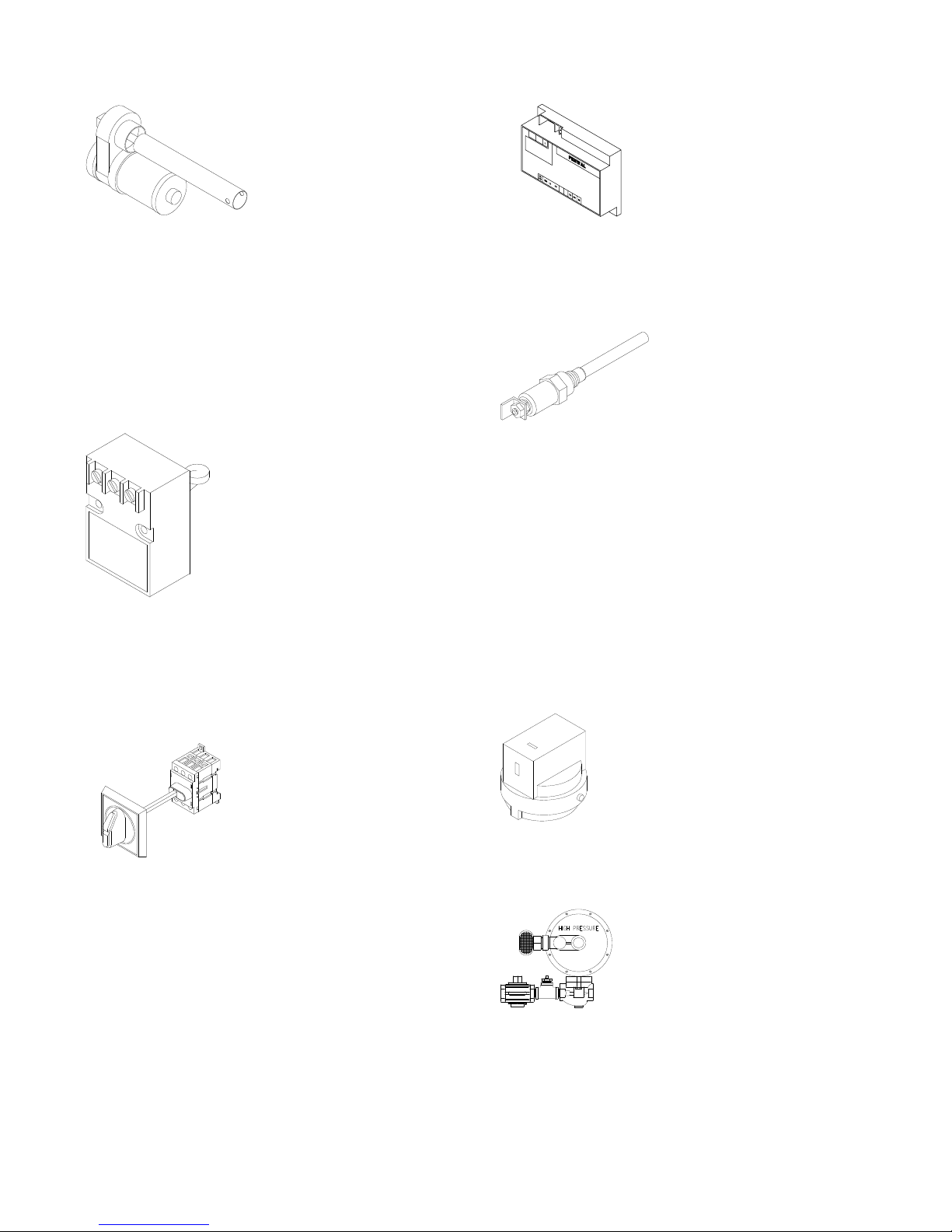
DAMPER MOTOR
The damper motor operates on 24
Volts AC and transmits power to
the motor starter when the damper blades are fully open by the
closure of the damper end switch.
The damper end switch is an
adjustable internal auxiliary
switch which has been factory set to operate when the
damper is fully open. The damper motor will power closed
when the heater cycles off. The damper motor will not
close unless the blower service switch is in the
“REMOTE” position. Refer to detailed instructions
regarding the replacement and adjustment of the damper
motor (see page 53).
DISCHARGE TEMPERATURE SENSOR
The discharge temperature sensor is
mounted on the fan housing and is a
component of the Maxitrol Series 14
and Series 44 temperature control systems. It senses the average fan discharge temperature and transmits a
resistance signal back to the amplifier that corresponds to the dis-
charge temperature. The Maxitrol
Series 44 and Maxitrol Series 44/Tamperproof temperature control systems use the Maxitrol Series 44 sensor
(TS144). The Maxitrol Series 14 control systems use the
Maxitrol Series 14 sensor (TS114).
DISCONNECT SWITCH
The non-fused disconnect switch
is provided on all heaters and
includes a lockable operating
knob. The disconnect must be off
before accessing the electrical control enclosure. Once the control enclo-
sure is open, experienced service
technicians may activate the electrical circuit to assist in troubleshooting.
EXHAUST FAN CONTACT
The exhaust fan contact is an auxiliary dry contact that
is mechanically interlocked to operation of the heater’s
motor starter and is provided with terminals located in
heater’s electrical enclosure. The dry contact is typically
wired into an exhaust fan control circuit to activate the
exhaust fan as a slave to the make-up air heater.
FLAME SAFEGUARD RELAY
The flame safeguard relay supplies
24 Volts AC to the igniter for 4
seconds prior to the gas valve
being energized. If the burner
does not light (flame is not established within 7 seconds), this control
will lock out. If flame signal is lost
during burner operation, the control will allow one retry
for ignition.
FLAME ROD
The flame rod senses the presence of flame, and signals the
flame safeguard relay. The presence of flame is detected by the
flame rectification of the AC sig-
nal that is supplied to the flame
rod, thus creating the DC response. The resulting current
flow produced can be measured with a DC microammeter. The reading should be steady and between 2.0 and
6.0 microamps (mA).
FUSE BLOCK
The fuse block provides line fusing for
branch circuit protection. It is wired in
conjunction with the non-fused disconnect switch.
HIGH GAS PRESSURE SWITCH
The high gas pressure switch is a manual reset
safety device to lock out the burner operation
should large gas pressure fluctuations
occur. The high gas pressure switch
should be set at 25% above manifold gas
pressure. The adjustment screw is located
under the top plate.
HIGH PRESSURE REGULATOR
The high pressure regulator is required
when the gas supply pressure exceeds
the nameplate rating for the heater.
The high pressure regulator assembly
is also furnished with a high gas pres-
sure manual shut-off valve and a tap for
measuring the upstream gas pressure. The high pressure
regulator is a positive lock-up type regulator which must
be vented to the outdoors. It is sized according to the gas
supply pressure and the capacity requirements of the heater.
M-Series Technical Manual 67 Cambridge Engineering, Inc.
Page 70
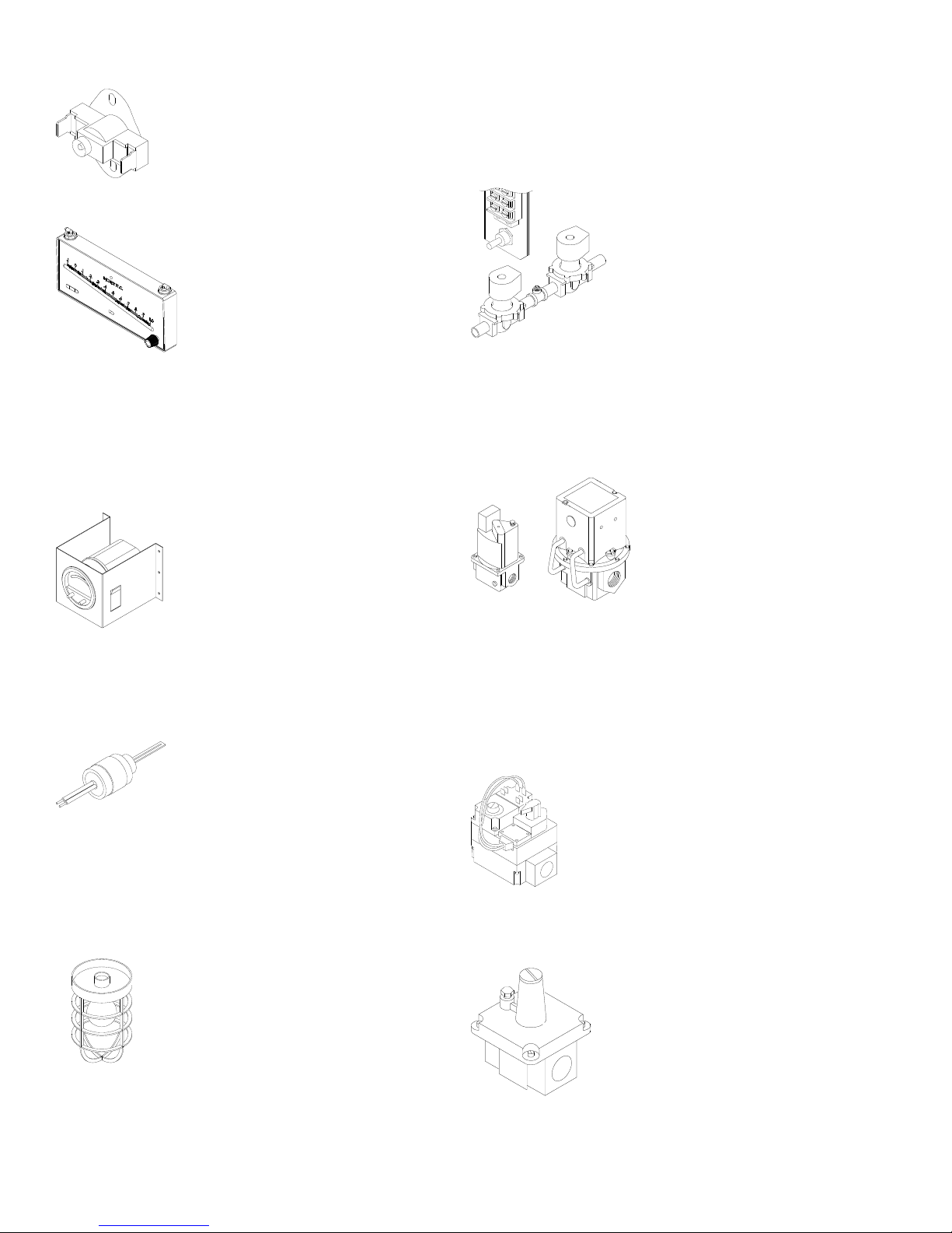
HIGH TEMPERATURE LIMIT
The high temperature limit opens when
the discharge air temperature exceeds
150˚F. This limit must be manually reset.
INCLINED MANOMETER
An inclined manometer with a range of
-0.1 to 1.0 inch WC is provided on each
heater with manual profile damper
adjustment to indicate the pressure drop
across the burner profile plate. The
pressure drop should be set without the
burner operating (blower only) at 0.68
inch WC for natural gas applications
and 0.90 inch WC for LP applications. If the heater is supplied with a filter section or filters in the rainhood, increase
the manometer reading to 0.72 inch WC for natural gas and
to 0.94 inch WC for LP gas heaters.
DIFFERENTIAL PRESSURE SWITCH/GAUGE
A differential pressure switch/gauge is
available as part of the Automatic
Prole Adjust system to control the
pressure drop across the burner prole
plate. The differential pressure switch
drives a Prole Damper Adjust Motor
to maintain approximately 0.68 inch
WC for natural gas applications, or approximately 0.90
inch WC for LP applications.
IGNITER
The hot surface igniter is the ignition
source for lighting the gas in the burner. It is made of silicon carbide which
is very fragile. Care should be used in
handling. It operates on 24 Volts and
the current ranges from 1.3 to 1.7 amps. It will reach
temperatures in excess of 2400˚F during the ignition
trial. It is furnished with a sleeve for shock mounting and
sealing the igniter in the mounting tube.
heater’s electrical enclosure. Furnished with safety
guards. 100 watts maximum, each. A separate electrical
supply source is required.
LEAK TEST FACILITY
The leak test facility is provided on
all heaters over 400,000 Btu/hr and
consists of a momentary switch for
the first safety shut-off valve in the
gas train and a gauge port between
the first and second safety shut-off
valve. By holding the gas valve
momentary switch closed, the first
gas valve is energized which allows
gas pressure to build on the seat of the second gas valve.
The gauge port between valves is used to determine if
the first gas valve seat is properly sealed.
MODULATING VALVE
The modulating valve responds
to a 4 to 24 Volt DC signal
from the amplifier to modulate
the flow of gas to the burner. On
the Maxitrol M511 or M611
valve, the minimum fire adjusting
screw is located on the far side
of the valve under the dust cover. On the Maxitrol
MR212 valve, the minimum fire adjusting screw is located
under the large dust cover. The MR212 modulating valve also
serves as the manifold pressure regulator to control the
burner manifold pressure. The MR212 is rated for 5
PSIG.
COMBINATION VALVE
The combination valve serves as a manifold pressure regulator and redundant gas
shut-off valve. This control is typically
used for gas capacities below 400,000 Btu/hr.
The valve operates on 24 Volts AC power.
The combination valve is rated for a maxi-
mum gas supply pressure of 14 inches WC.
INTERIOR LIGHT(S)
Available for the heater cabinet, electrical
control enclosure, and/or gas train enclosure. Light switches are located inside the
Cambridge Engineering, Inc. 68 M-Series Technical Manual
MANIFOLD PRESSURE REGULATOR
The manifold pressure regulator controls the burner manifold pressure.
When the MR212 valve is used, this
Page 71
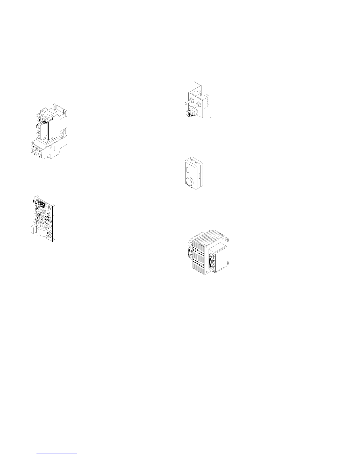
modulating valve also serves as the pressure regulator.
The maximum gas supply pressure rating is normally
determined by the exposed pressure rating of the regulating device. The RV61 and RV81 are rated at 1 PSIG;
and the MR212 is rated at 5 PSIG. (For make-up air
heaters rated at 400,000 Btu/hr or below, see the combination valve above.)
MOTOR STARTER, OVERLOAD,
& AUXILIARY CONTACT
The motor starter assembly consists of a
motor starter, overload relay and auxiliary
contact. The overload relay protects the
motor from excessive current or single phasing. If the overload relay trips, it must be
reset manually. The auxiliary contacts
are used in the gas valve safety circuit as
an indication the blower is operating, and
as an optional exhaust fan contact for interlocking other
equipment with the operation of the heater.
MULTI-FUNCTIONAL PC BOARD
The multi-functional PC board provides five
(5) separate functions for heaters with the
Maxitrol Series 14 or Series 44 controls. The
functions are as follows:
1) Blower Relay (CR1) which is energized on a “call for blower” from the
Remote Control Station.
2) The LTC (Low Temperature Cutout) circuit functions to turn off the blower in approximately 3 1/2
minutes if any of the following occurs: (a) The
inlet temperature drops below the selectable LTC
setpoint (40˚F, 45˚F, 50˚F, or 55˚F) in the ventilation mode; (b) the gas valve fails to remain energized during a heating cycle or (c) the high airflow
switch contacts indicate the burner profile plate
pressure drop is too high.
3) The EAT (Entering Air Thermostat) circuit functions automatically to turn off the burner when the
outdoor temperature reaches the selectable EAT
setpoint (45˚F, 50˚F, 55˚F, 57.5˚F, 60˚F, 62˚F,
64˚F, 66˚F, 68˚F or 70˚F).
4) The PT (Purge Timer) circuit function is preset
at the factory to provide four air changes within
the heater cabinet prior to an ignition attempt
(normally set at 4 or 8 seconds). If inlet ducting
is attached to the heater, the delay time can be
increased to 8, 16, or 32 seconds, as applicable.
5) The patented LFS (Low Fire Start) circuit func-
tion limits the initial heater firing for the first 15 seconds of a heating cycle to obtain proper ignition.
The voltage to the modulating valve is adjusted
between 9 and 13 Volts DC by an adjustable
potentiometer on the multi-functional PC board.
SERVICE SWITCH
The service switches are mounted in the
electrical control enclosure. In the
“LOCAL”
or “OFF” position, the service technician has local control of the heater. These
switches must be placed in the “REMOTE”
position for normal control from the Remote Control
Station.
SPACE TEMPERATURE SELECTOR
The space temperature selector is part of the
Maxitrol Series 44 control system. The space
temperature selector senses the space temperature.
A 3˚F drift above the set temperature will cause
the heater to modulate to the MIN setting on the
amplifier and a 3˚F drift below the set temperature will cause
the heater to modulate to the MAX setting.
TRANSFORMER
Heaters are furnished with a dual
voltage transformer unless the primary voltage is 115 Volts. The
transformer furnished depends on
the primary voltage (208, 230, 460
or 575 Volts). This transformer provides secondary control voltages of
24 and 115 Volts. Heaters supplied
for 115 Volts are furnished with a 24 Volt secondary
transformer only. Secondary fusing is provided in all
Class I transformer circuits to protect the downstream
components from short circuit. Fuse sizing is as follows:
FNM-6.25 for 150 va 24 Volt and FNM-1.6 for 150 va
115 Volt. Consult the heater wiring diagram to identify
the proper fusing for the heater in question. Do not
increase the fuse rating over that which is specified.
M-Series Technical Manual 69 Cambridge Engineering, Inc.
Page 72
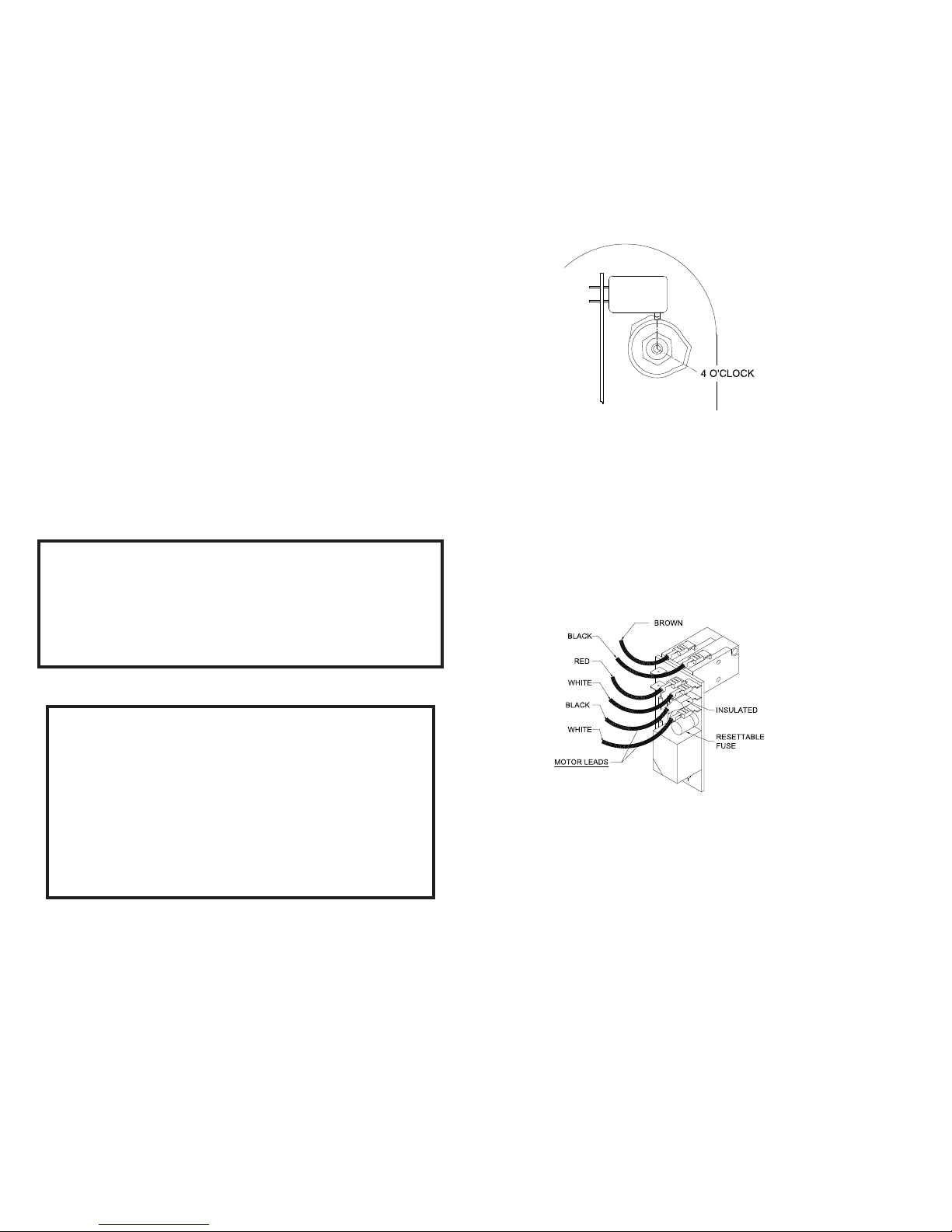
DAMPER MOTOR REPLACEMENT & ADJUSTMENT
1. Before re-installing the damper motor into the heater
assembly, remove the black plastic weather cover
from the damper motor by removing the screw that
secures the cover to the damper assembly using either
a flat tip screw driver or a 1/4" nut driver. It may be
necessary to twist the cover slightly to disengage it
from its mounting to the end of the motor after the
screw is removed.
2. Verify the damper motor is in the closed position
(Drive tube is retracted with a minimum of 1/4" gap
between drive tube and body of the damper assembly).
3. Verify the inner cam has fully engaged the lower limit
switch plunger and the lower limit switch (next to the
body of the damper motor) shows continuity between
the common (C) terminal and the normally open (NO)
terminal.
CAUTION:
If the lower limit switch does not indicate continuity,
the damper motor must be driven to the fully closed
position before connecting the damper linkage to the
drive tube of the damper assembly.
a deep well 1/2" hex socket or nut driver to manually rotate the cam counterclockwise a few clicks, as
required, to obtain the correct starting position (see
Figure 1).
Figure 1
5. Verify the heater disconnect switch is turned off and
the Service Switches are in the “OFF” position.
6. Connect wires to terminals as shown in Figure 2 and
re-install the weather cover.
CAUTION:
If the drive tube bottoms out against the damper
motor housing, damage to the PC board or tripping of the onboard fuse may result. If the fuse
trips, place the blower service switch in the “OFF”
position for 15 seconds to allow the fuse to reset.
Proceed with steps 4 through 10 BEFORE connecting the damper motor to the linkage arm.
4. Verify the cam location on the upper cam is set just
short of the four o’clock position with respect to the
switch plunger being the twelve o’clock reference
position. If it is beyond the four o’clock position, use
7. Remove the push-in plug (located in the weather
cover) to have access to the upper cam adjusting nut.
8. Connect the motor pivot to the damper motor support
bracket using the 3/8" diameter clevis pin. Do not
connect the damper linkage at this time.
Cambridge Engineering, Inc. 70 M-Series Technical Manual
Figure 2
Page 73

9. Remove the wire from the “G” terminal of the terminal block. (This is to avoid a “Call-for-Fan” signal
from the Remote Control Station during the next two
steps).
10. Let the damper assembly hang down (suspended
by the damper motor support bracket) and turn
the heater disconnect on and momentarily turn the
blower service switch to the “LOCAL” position (for
approximately 5 seconds). Do not restrain the drive
tube from turning freely. Then, turn the blower
service switch to the “REMOTE” position until the
damper motor drive tube stops turning. (Drive tube is
now fully retracted).
11. Turn the heater disconnect switch off and manually
trip the motor starter overload. The manual trip lever
is located on the overload between the overload and
the motor starter.
12. Connect the damper linkage to the drive tube by
manually rotating the drive tube in 1/2 turn increments until the 3/8" diameter bolt can seat into the
nut on the damper linkage. Maintain the damper
blades in the tightly-held, fully closed position during this adjustment.
15. Turn the blower service switch to the “REMOTE”
position and, after the damper motor closes, turn the
heater disconnect off.
16. Re-install the weather cover push-in plug.
17. Re-connect the wire removed in step 9 to terminal
“G” and reset the motor starter overload.
18. Verify both service switches are in the “REMOTE”
position, close the electrical enclosure door and turn
the heater disconnect switch on.
13. Turn the heater disconnect switch on and place the
blower service switch to the “LOCAL” position.
Damper will open to the point the upper cam engages the upper limit switch.
14. Using the deep-well, 1/2" hex socket or nut driver,
turn the upper cam hex nut in a clockwise
direction in one click increments until the damper
blades fully open.
CAUTION:
Do not over-drive the damper motor as damage to the
PC board or tripping of the onboard fuse may result.
If the fuse trips, place the blower service switch in the
“OFF” position for 15 seconds to allow fuse to reset.
M-Series Technical Manual 71 Cambridge Engineering, Inc.
Page 74
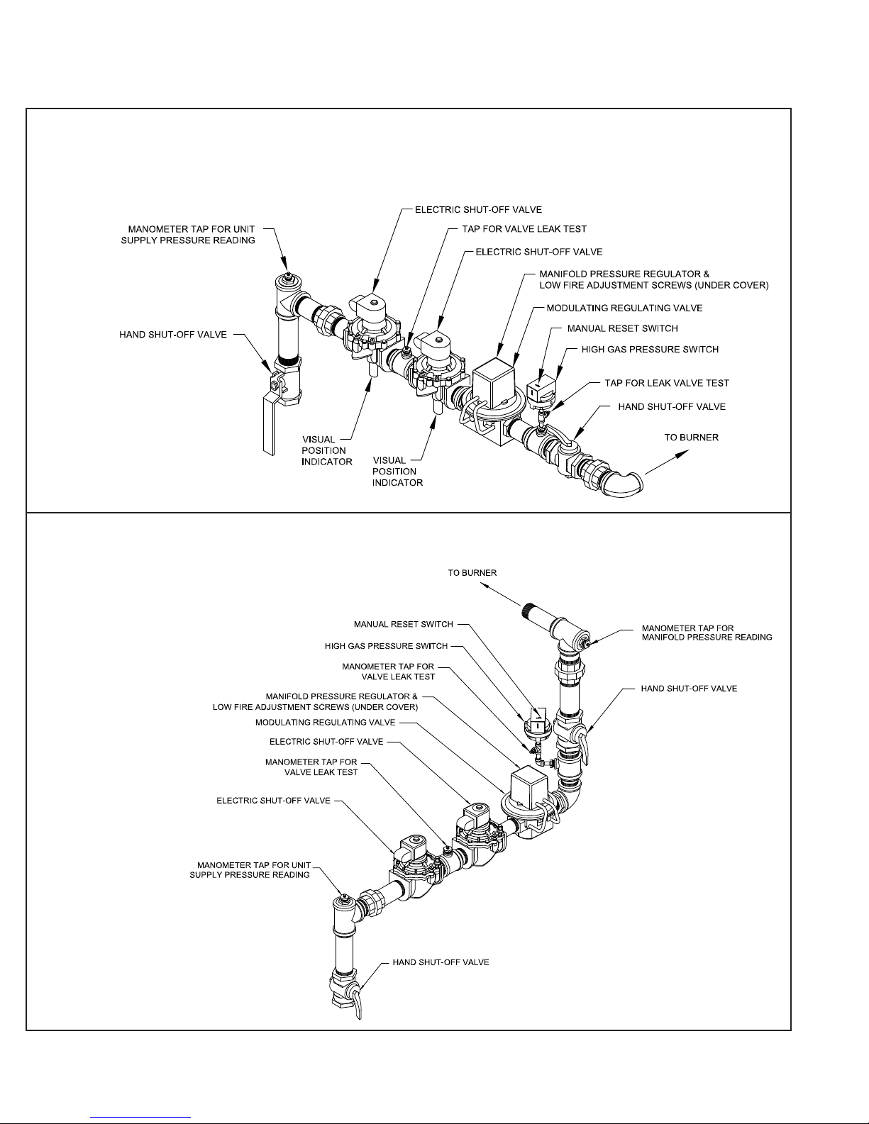
GAS TRAIN DRAWINGS (FM & IRI)
Vertical Mount
> 2500 MBH
Factory Mutual (FM) Compliant
CSA Certified
Horizontal Mount
> 400 MBH
Industrial Risk Insurers (IRI) Compliant
CSA Certified
Cambridge Engineering, Inc. 72 M-Series Technical Manual
Page 75

TROUBLESHOOTING GUIDE
Problem Possible Cause Corrective Action
1. Make-up air heater in Reset
I. No Blower Operation
a) Outside temperature below LTC setpointin Vent Mode
b) Gas Valve not energized during call for
heat cycle
c) Pressure drop across burner too high
d) Sustained excessive winds present
e) High Air Flow Switch defective
2. Heater Disconnect
a) Disconnect in OFF position
3. Mode Selector Switch on RCS
a) Switch in OFF position a) Place switch in proper mode.
4. Operating Thermostat
a) Thermostat satisfied
b) Open in thermistor circuit
c) Defective thermostat
5. Blower Service Switch
a) Switch in OFF position
b) Defective switch
6. Control Transformer
a) No input voltage
b) Blown control fuse
C) Defective transformer
7. Class II Transformer
a) No output voltage
b) Defective transformer
8. Multi-Functional PC Board
a) No input voltage on Terminal G (RCS)
b) Improper wiring
c) Defective board
9. Damper Motor
a) Damper End Switch not made
b) Damper motor not operating
c) Defective damper motor
10. Motor Protection
a) Overload relay tripped
b) Overload relay defective
11. Motor Starter
a) Coil open (Defective)
b) Contacts welded closed (Defective)
12. Motor
a) No input voltage
b) Improper voltage
c) Defective motor
13. Blower Damage
a) Defective or locked bearings
b) Physical damage
14. Belts
a) Belt Slipping
b) Belt broken or missing
a) Turn heater “OFF” momentarily and turn
heater “ON.”
b) See Problem III.
c) Adjust Profile Plate Damper.
d) Wait until winds abate and reset.
e) Replace High Air Flow Switch.
a) Turn disconnect ON.
a) Adjust thermostat, if applicable.
b) Check wiring or replace thermistor.
c) Replace thermostat.
a) Place switch in REMOTE position.
b) Replace switch.
a) Check disconnect and supply fusing.
b) Replace control fuse.
c) Replace transformer.
a) Check supply voltage.
b) Replace transformer.
a) Check voltage in RCS.
b) Check wiring.
c) Replace multi-functional PC board.
a) Check end switch/cam interface.
b) Check end switch/cam interface
b1) Check damper fuse.
b2) Check diodes on switch assy
c) Replace damper motor
a1) Check primary power source
a2) Reset overload relay and check motor
amps/overload setting.
b) Replace overload relay
a) Replace starter.
b) Replace starter.
a) Check primary power source.
b) Consult factory.
c) Replace motor.
a) Replace bearings.
b) Replace or repair blower
a) Tighten belts.
b) Replace belts
M-Series Technical Manual 73 Cambridge Engineering, Inc.
Page 76

TROUBLESHOOTING GUIDE
Problem Possible Cause Corrective Action
II. BLOWER RUNS;
NO HEAT;
FLAME SAFETY
RELAY DOESN’T
LOCK OUT
III. BLOWER RUNS;
NO HEAT;
FLAME SAFETY
RELAY LOCKS OUT
1. Mode Selector Switch
a) Switch in VENT position a) Place switch in HEAT position.
2. Burner Service Switch
a) Switch in OFF position a) Place switch in REMOTE position.
3. Multi-Functional PC Board
a) No input voltage on Terminal W (RCS)
b) Thermostat satisfied
c) Improper wiring
d) Defective board
4. Airflow Switch
a) Blower running backwards
b) Belts slipping
c) Blocked intake or discharge
d) Clogged airflow tubing or pickup ports
e) Defective switch
5. Flame Safeguard Relay (FSR)
a) No input voltage
b) Defective FSR
6. Entering Air Thermostat (EAT)
a) EAT set too low
1. Igniter
a) No current (open igniter)
b) No voltage
2. High Limit
a) High limit tripped a) See Problem Number VI
3. High or Low Gas Pressure Switches
a) Low gas pressure switch tripped
b) High gas pressure switch tripped
c) Defective gas pressure switch
4. Gas Valve
a) No input voltage
b) Gas valve does not open
c) Defective solenoid
5. Modulating Valve
a) Minimum fire set too low a) Adjust minimum fire on modulating valve
6. Multi-Functional PC Board
a) Low fire start set too low
b) Thermistor open or not connected
a) Check voltage in RCS.
b) Adjust thermostat.
c) Check wiring to multi-functional PC
board.
d) Replace multi-functional PC board.
a) Reverse motor direction.
b) Tighten and/or replace belts.
c) Find and remove obstruction.
d) Clean or replace tubing or pickup ports.
e) Replace switch.
a) Check wiring.
b) Replace FSR
a) Increase EAT setting
During trial for ignition:
a) Check igniter current
b) Check FSR output to igniter.
a) Check gas supply for low gas pressure or
no gas
b1) Check manifold gas pressure for high
pressure reading and reset pressure regulator
b2) Check gas supply pressure against name
plate
b3) Verify the high pressure regulator is a
lock-up type
c) Replace gas pressure switch
a1) Check FSR output to R1 relay
during ignition trial
a2) Check gas valve circuit and wiring
b1) Compare supply voltage to nameplate
voltage
b2) Clean and/or replace gas valve parts.
c) Replace solenoid or valve assembly.
a) Adjust modulating valve voltage between
10 and 13 Volts DC
b) Properly install or replace thermistor
Cambridge Engineering, Inc. 74 M-Series Technical Manual
Page 77

TROUBLESHOOTING GUIDE
Problem Possible Cause Corrective Action
III. BLOWER RUNS;
NO HEAT; FLAME
SAFETY RELAY
LOCKS OUT
(Continued)
IV. BLOWER RUNS;
BURNER FIRES;
FLAME SAFETY
RELAY LOCKS OUT
V. BLOWER RUNS;
UNIT HEATS;
SHORT CYCLES
WITHOUT
RESETTING
7. Regulator
a) Clogged vent orifice
b) No supply pressure
c) Improper manifold pressure
d) Defective regulator
8. Burner
a) Defective burner a) Replace burner.
1. Low Flame Current
a) Dirt build-up on insulator
b) Minimum fire set too low
c) Defective burner
2. Multi-Functional PC Board
a) Low fire start set too low
3. No Flame Current
a) Ground connection open
b) Wire termination oxidized
4. Fluctuating Flame Current
a) Unit overfiring
b) Minimum fire set too low
c) Intermittent ground connection
d) Defective burner
5. Flame Safeguard Relay
a) Defective FSR a) Replace FSR
6. High Limit
a) High limit contact intermittent a) Replace high limit.
1. Air Flow Switch
a) Blower running backwards
b) Belts slipping
c) Blocked intake or discharge
d) Air delivery below minimum requirements
e) Clogged airflow tubing or pick-up ports
f) Defective switch
2. Flame Safeguard Relay
a) Defective FSR a) Replace FSR.
3. Operating Thermostat
a) Differential temperature setting too tight a) Increase differential temperature setting
4. Damper Motor End Switch
a) End switch making intermittent contact a) Replace end switch assembly.
a) Clean or replace orifice
b) Check all gas cocks and piping
c) Adjust regulator.
d) Replace regulator.
a) Clean dirt deposit from insulator
surface and install protective boot.
b) Adjust minimum fire on modulating valve
c) Replace burner.
a) Adjust modulating valve voltage between
9 and 13 Volts DC
a1) Reference transformer to ground.
a2) Secure FSR grounded.
a3) Tighten loose ground screws
b) Clean terminal and reinsert
a) Check manifold pressure.
b) Adjust minimum fire on modulating valve.
c) Tighten all ground points
d) e) Replace burner.
a) Reverse motor direction
b) Tighten and/or replace belts
c) Find and remove obstruction.
d) Increase fan RPM for air delivery require-
ments.
e) Clean or replace airflow tubing or pick-up
ports
f) Replace switch.
M-Series Technical Manual 75 Cambridge Engineering, Inc.
Page 78

TROUBLESHOOTING GUIDE
Problem Possible Cause Corrective Action
VI. HIGH LIMIT TRIPPED
1. High Limit
a) High limit will not reset a) Replace high limit.
VII. BLOWER RUNS;
UNIT HEATS;
WILL NOT CYCLE
OFF
VIII. MODULATING
VALVE DOES NOT
MODULATE;
CONTINUOUS
HIGH FIRE
2. Burner Overfiring
a) Manifold pressure too high
3. Discharge Damper
a) Damper blades partially closed
b) Defective damper motor
4. Low Airflow
a) Blower running backwards
b) Belts slipping
c) Blocked intake or discharge
5. Temperature Control System
a) Temperature control system does not
modulate
1. Operating Thermostat
a) Short in thermistor circuit
b) Thermostat located improperly
c) Thermostat differential setting too wide
d) Defective thermostat
2. Burner Service Switch
a) Switch in LOCAL position a) Place switch in REMOTE position.
3. Auxiliary Control
a) Auxiliary contacts closed
4. Misunderstood Control System
Operation
a) Control system doesn’t function as
expected
1. Amplifier (A1014 or A1044)
a) Wire not connected to amplifier terminal
3 or 4.
b) Jumper not installed between terminals 2
and 3 of A1014 amplifier only.
c) Defective amplifier
2. Discharge Temperature Sensor
(TS114 or TS144)
a) Open in sensor circuit
b) Sensor cross-wired to amplifier
3. Space Temperature Selector
(Series 44 only) (T244 or TS244/TD244)
a) Open in sensor circuit
b) Induced voltage in field wiring
c) Space sensor located improperly
a) Adjust manifold pressure regulator to
obtain temperature rise specified on heater
nameplate.
a) Adjust damper stroke length.
b) Replace damper motor.
a) Reverse motor direction.
b) Tighten or replace belts.
c) Find and remove obstruction
a) See problem VIII for Electronic Discharge
Control systems.
a) Check thermistor wiring and/or replace
thermistor.
b1) Thermostat in cold draft-relocate.
b2) Thermostat not satisfied-turn down
c) Reduce differential setting.
d) Replace thermostat.
a) Check auxiliary circuit wiring and
contacts
a) Review control system operational charac-
teristics.
a) Reinstall wire.
b) Reinstall jumper.
c) Replace amplifier.
a) Replace the sensor if the resistance mea-
sured at terminals 1 and 2 on TS114 sen-
sor exceeds 11,000 Ω; terminals 1 and 3
or 2 and 3 onTS144 exceeds 6,000Ω.
c) Correct wiring terminations.
a) Replace the sensor if the resistance mea-
sured is more than: 7,000 Ω for the T244;
5,500 Ω for the TS244; or 2,250 Ω for the
TD244.
b) Utilize shielded, twisted pair wiring
c) Sensor in cold draft - relocate
Cambridge Engineering, Inc. 76 M-Series Technical Manual
Page 79

TROUBLESHOOTING GUIDE
Problem Possible Cause Corrective Action
VIII. MODULATING
VALVE DOES NOT
MODULATE;
CONTINUOUS
HIGH FIRE
(Continued)
IX. MODULATING VALVE
DOES NOT
MODULATE;
CONTINUOUS
LOW FIRE
4. Space thermostat (Series 14 only)
a) Thermostat out of calibration
b) Thermostat located improperly
c) Thermostat differential setting too wide
d) Thermostat defective
5. Remote Heat Adjust (TD114)
a) Short in Remote Heat Adjust circuit
b) Induced voltage in field wiring
6. Modulating Valve (M511, M611 or
MR212)
a) Foreign material holding valve open
b) Modulating valve misassembled
1. Class II Transformer
a) No voltage output to amplifier a1) Check for short in modulating valve coil.
2. Modulating Valve
a) Valve coil is open or shorted
b) Plunger jammed
c) Ruptured main or balancing diaphragm
3. Amplifier
a) No output voltage to valve
4. Discharge Temperature Sensor
(TS114 or TS144)
a) Short in sensor circuit
b) Temperature control system out of cali-
bration
a) Recalibrate thermostat or replace.
b) Thermostat in cold draft - relocate.
c) Reduce differential setting.
d) Replace thermostat.
a) Replace Remote Heat Adjust if resistance
measure between terminals 1 and 3 of
Remote Heat Adjust is less than 6,000 Ω.
b) Utilize shielded, twisted pair wiring.
a) Disassemble valve and remove foreign
material.
b) Disassemble valve and assemble correctly
a2) Replace transformer.
a) Replace valve coil if its resistance is less
than 40 Ω or greater than 85 Ω.
b) Clean or replace plunger.
c) Check diaphragm condition and replace if
defective.
a) With the wire removed from terminal 3
of amplifier, replace amplifier if the valve
voltage does not exceed 18 Volts DC.
a) Replace the sensor if the resistance mea-
sured at: terminals 1 and 2 on TS114 is
less than 8,000 Ω; terminals 1 and 3 or 2
and 3 on TS144 is less than 2,900 Ω.
b) Perform temperature control system cali-
bration.
M-Series Technical Manual 77 Cambridge Engineering, Inc.
Page 80

TROUBLESHOOTING GUIDE
Problem Possible Cause Corrective Action
IX. MODULATING
VALVE DOES NOT
MODULATE;
CONTINUOUS
LOW FIRE
(Continued)
5. Space Temperature Selector
(T244A or TS244A/TD244A)
a) Short in sensor circuit a) Replace the sensor if the resistance mea-
6. Remote Heat Adjust
(TD114)
a) Open in the Remote Heat Adjust control
circuit
sure is less than 5,000 Ω for the T244A or
3,500 Ω for the TS244A and 1,950 Ω for
the TS244A.
a) Replace the control if the resistance
measured at terminals 1 and 3 exceeds
12,000 Ω.
X. ERRATIC OR
PULSATING FLAME
7. High Airflow Switch
a) Pressure drop across burner too high
b) Defective Airflow Switch
8. Multi-Functional PC Board
a) Temp sensor wires not seated properly in
terminal block.
b) Defective board
1. High Pressure Regulator
a) Vent undersized
b) Defective regulator
2. Amplifier
a) Hunting
b) Temperature control system out of cali-
bration
c) Defective amplifier
3. Space Temperature Selector
(T244A or TS244A/TD244A)
a) Induced voltage in field wiring a) Utilize shielded, twisted pair wiring.
4. Remote Heat Adjust (TD114)
a) Induced voltage in field wiring
a) Measure pressure drop and adjust profile
damper.
b) Replace Airflow Switch.
a) Reinstall sensor wires.
b) Replace board.
a) Enlarge vent piping size or reduce vent
piping length.
b) Replace regulator.
a) Adjust sensitivity control dial counter-
clockwise.
b) Perform temperature control system
calibration.
c) Replace amplifier.
a) Utilize shielded, twisted pair wiring.
Cambridge Engineering, Inc. 78 M-Series Technical Manual
Page 81

ANSI/ASHRAE/IESNA STANDARD 90.1
Overview
Energy efficient, Genuine Cambridge
gas-fired heating equipment can comply with the
requirements of ANSI/ASHRAE/IESNA Standard
90.1. Compliance is shown on the Cambridge heater
nameplate.
Purpose of ASHRAE Standard 90.1
ASHRAE Standard 90.1 provides minimum requirements for the energy efficient design and construction of new commercial buildings in the United
States. The standard covers the entire building,
setting minimum equipment efficiency levels for
components that may be used, rather than setting
standards for component manufacturing.The provisions of this standard do not apply to single family
houses, low rise residential buildings and buildings
(or portions of buildings) that use energy primarily
for industrial, manufacturing or commercial processes.
®
direct
• Damper (Section 6.4.3.4.3)
A damper is required on each heater. The
Cambridge Engineering Motorized Discharge
Damper (MDD) will meet the standard.
• Labeling (Section 6.4.1.5.1)
The heater must be labeled to indicate that it
complies with the requirements of the standard.
The nameplate of Cambridge heaters includes the
required labeling.
• Efficiency (Section 6.4.1.3)
Direct gas-fired heating equipment has no
minimum efficiency requirement. However
Cambridge Engineering certifies that its equipment has a 100% combustion efficiency (Ec) and
a 92% thermal efficiency (Et).
Compliance Requirements:
The following are required for Cambridge heaters to
comply with Standard 90.1:
• Controls (Section 6.4.3)
Total airflow of all heaters less than 10,000
cfm - The Cambridge Engineering Temperature
Setback System (TSS) will meet the standard. A
properly configured building DDC system with
the necessary programming for zone control,
automatic shutdown and setback can also meet
the standard.
Total airflow of all heaters exceeds 10,000
cfm - The Cambridge Engineering Temperature
Setback System (TSS) with optimum start control will meet the standard. A properly configured building DDC system with the necessary
programming for zone control, automatic shutdown, setback and optimum start can also meet
the standard.
Heaters intended to operate continuously - No
special controls are required to meet the standard.
M-Series Technical Manual 79 Cambridge Engineering, Inc.
Page 82

MAINTENANCE LOG
MODEL NO. SERIAL NO.
Date
Activity Technician
Cambridge Engineering, Inc. 80 M-Series Technical Manual
Page 83

Cambridge Engineering, Inc. reserves the right to change specifications, modify the design and/or
substitute equivalent materials without notice as the result of code requirements, product enhancements,
ongoing research/development and vendor changes beyond our control.
Page 84

760 Long Road Crossing Dr., Chesterfield, MO 63006
Phone: (800) 899-1989, Fax: (636) 530-6133
www.cambridge-eng.com
 Loading...