

Page 1
Qt® Conference Room Edition
A speech protection system designed for conference rooms
Installation and Operations Guide
Page 2

page 3
Qt Conference Room Edition Installation and Operations Guide
SAFETY
Safety
Important Safety Instructions:
1. Read these instructions.
2. Keep these instructions.
3. Heed all warnings.
4. Follow all instructions.
5. Do not use this apparatus near water. Indoor use only.
6. Clean only with dry cloth.
7. Do not block any ventilation openings. Install in accordance with the manufacturer’s instructions.
8. Do not install near any heat sources such as radiators, heat registers, stoves, or other apparatus
(including ampliers) that produce heat.
9. Do not defeat the safety purpose of the polarized or grounding-type plug. A polarized plug has two
blades with one wider than the other. A grounding type plug has two blades and a third grounding
prong. The wide blade or the third prong is provided for your safety. If the provided plug does not t
into your outlet, consult an electrician for replacement of the obsolete outlet.
10. Protect the power cord from being walked on or pinched particularly at plugs, convenience
receptacles, and the point where they exit from the apparatus.
11. Only use attachments/accessories specied by the manufacturer.
12. Unplug this apparatus during lightning storms or when unused for long periods of time.
13. Refer all servicing to qualied service personnel. Servicing is required when the apparatus has been
damaged in any way, such as power-supply cord or plug is damaged, liquid has been spilled or
objects have fallen into the apparatus, the apparatus has been exposed to rain or moisture, does not
operate normally, or has been dropped.
Page 3

page 4
Qt Conference Room Edition Installation and Operations Guide
Packing List
The package includes:
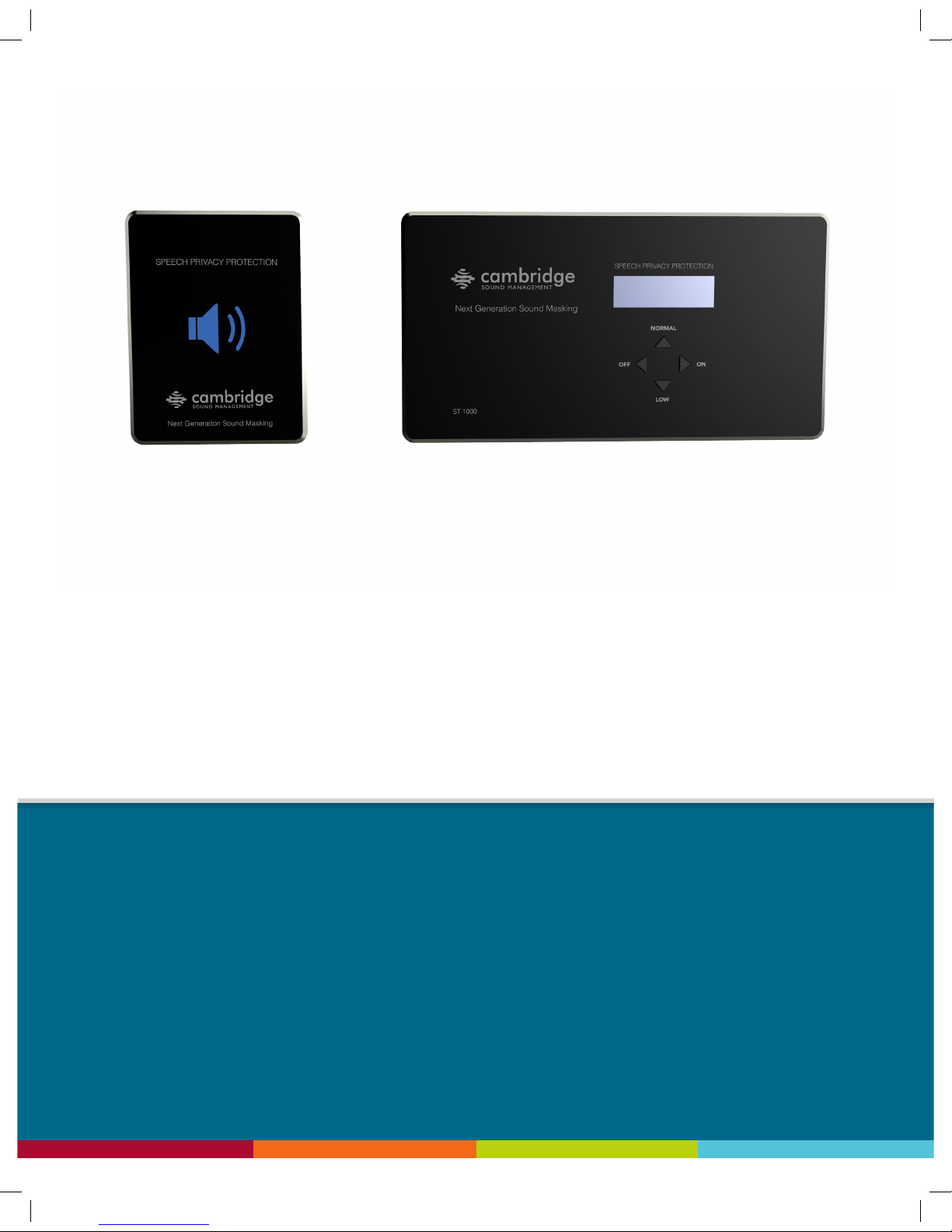
▪ 1 Wall-mounted ST 1000 control module
▪ 1 4-gang adaptor plate for control module (used for 3-gang EU/UK boxes)
▪ 2 Automatically lighted privacy signs
▪ 2 1-gang adaptor plate for privacy signs
▪ 1 Power supply
▪ 8 Qt Emitters
▪ 7 16 ft audio cables
▪ 1 50 ft homerun audio cable
▪ 2 50 ft two-conductor cables for privacy signs
▪ 1 Hole saw
▪ 4 Privacy sign 6/32” x 3/8” screws
▪ 8 Wall plate adapter 6/32” x 3/8” screws
▪ 4 Control module back panel 6/32” x 5/8” screws
PACKING LIST
Page 4

page 8
Qt Conference Room Edition Installation and Operations Guide
PLANNING THE SYSTEM
Emitter spacing and ceiling height
Spacing between emitters generally should follow the same rules as for other CSM direct eld masking
systems, i.e. should be not less than the ceiling height above the nished oor. The English dimensions
are based on America drop ceiling tile sizes (24x24”, 24x48”). The metric dimensions are based on
international tile sizes (300x300mm).
Ceiling Height
Ceiling heights less than 10 ft. (2.4m)
Ceiling height is 10 up to 12 ft. (3m)
Ceiling heights 12 ft. and above (3.6m)
8 ft. spacing (2.4m)
10 ft. spacing (3m)
12 ft. spacing (3.6m)
Spacing
Page 5
page 12
Qt Conference Room Edition Installation and Operations Guide
INSTALLATION
Installation
Pre-wiring
Homerun
The 50’ CAT distribution line supplied with the base kit should be sufcient as the
homerun for almost all installations. It may be replaced by a longer CAT cable
to the rst emitter without excessive loss or impact privacy signal level difference
between the rst and last emitters on the line. Theoretically a CAT coupler and
additional cable could be used rather than a longer homerun but this is not the
preferred method due to the coupler most likely being located in an inaccessible
and/or undocumented location, possibly complicating future servicing.
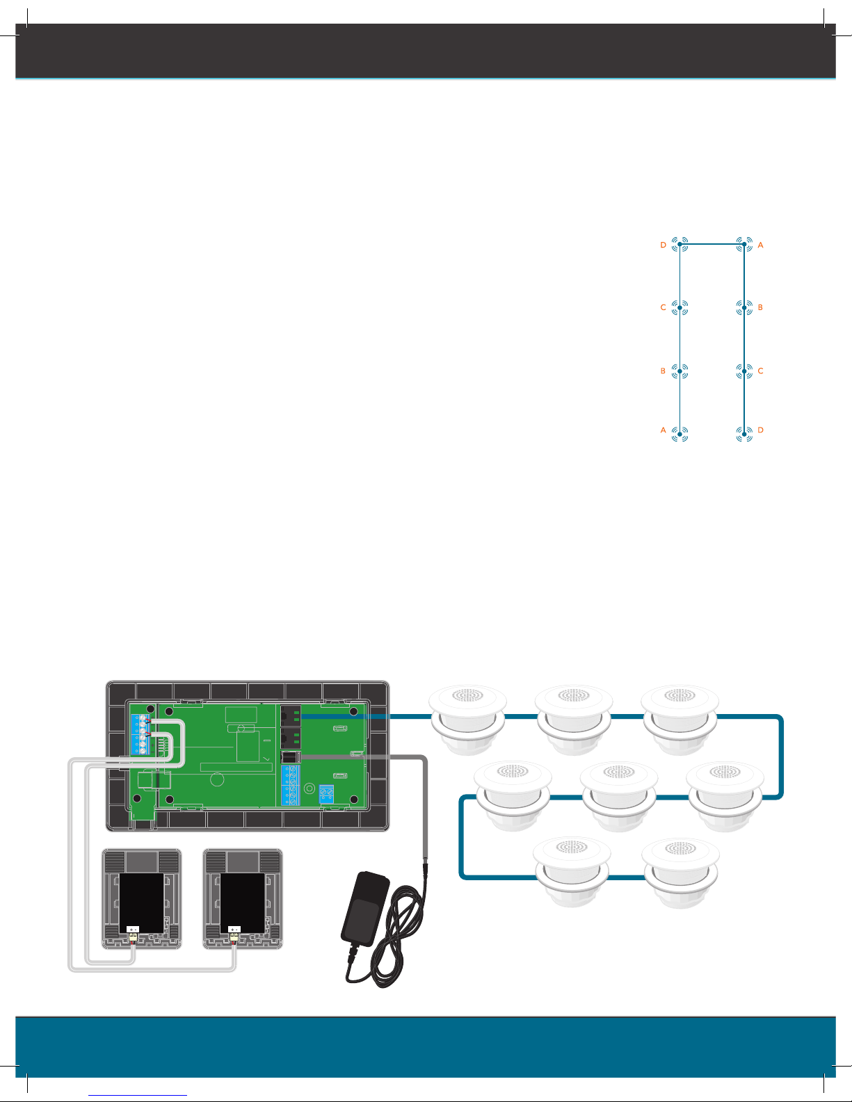
Emitter cable (interconnects) conguration
The interconnects should be connected the same as in a conventional CSM Qt
masking system, i.e. in a series serpentine layout. This will assure that adjacent
emitters are on different channels to minimize any phase interference issues.
CSM’s Quiet Technology uses four distinct non-correlated sounds that repeat every fourth emitter
automatically. The homerun from the controller to the rst emitter may be concealed in a wall stud
space.
How CSM emitter cabling works – homeruns and daisy chaining
Emitters on each line are daisy-chained in series during installation. Each emitter has passive internal
logic which rolls over its input channel to a different channel at its output port. Thus every fourth emitter
is actually operated in parallel with the rst.
Four Channel Distribution
Page 6
page 13
Qt Conference Room Edition Installation and Operations Guide
INSTALLATION
Power supply
In most cases the 24v power supply will need to be located remotely, with a cable run from the power
supply to the controller. In some cases a wall plate such as the Vanco 120614X permits in-wall running of
the power wire to an AC plug on the exterior of the wall.
The power supply wire may be extended using appropriate cable and connectors. The cable should be
UL rated and plenum rated if routed through any plenum space.
Audio Input
Optionally the QtCRE includes an audio input usable for music or paging. The input is fully functional
regardless of front panel or contact closure control. Therefore, the system may be used for music or
paging even when masking is muted or off.
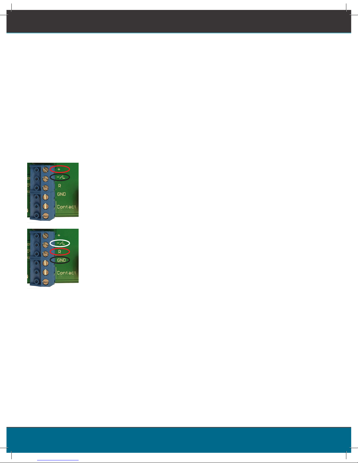
Balanced Audio Input: (Most often, but not always characteristic of paging
systems.) Connect signal wires to + and - at the input. Connect the shield to
GND at the audio source.
Unbalanced Audio Input: (Typical of music systems.)
▪ Mono Signals: Connect the mono signal wire to both L and R (split
the wire) on the block. Connect the ground wire to GND.
▪ Stereo Signals: Connect the respective signal wires to L and R on the
block. Connect the ground wire to GND.
Contact closure input
This terminal can be used either for remote triggering by a Crestron, AMX, or other control system.
In either case, the contract closure takes priority over the front panel control settings. Contact closure
ramp speed can be set separately from front panel control ramp speed.
Trigger output
The trigger output provides nominally 5VDC when the system is operating at Normal level, for use
in triggering other devices or to provide an acknowledgment signal back to an external automation
system like a Crestron. Note that upon initiation of a downward ramp event, deactivation of the trigger
signal will lag the completion of the downward ramp by several seconds in addition to the ramp down
time parameter congured on the ST1000 control module. During a ramp-up to Normal operating level
event, the full and consistent activation of the trigger voltage may not be complete until the Normal
operating level is reached. Control system programs should be written to anticipate and accommodate
this behavior.
Page 7
page 14
Qt Conference Room Edition Installation and Operations Guide
USB connection
(special purpose
see page 14)
Sign is
active
USB connection
in use
INSTALLATION
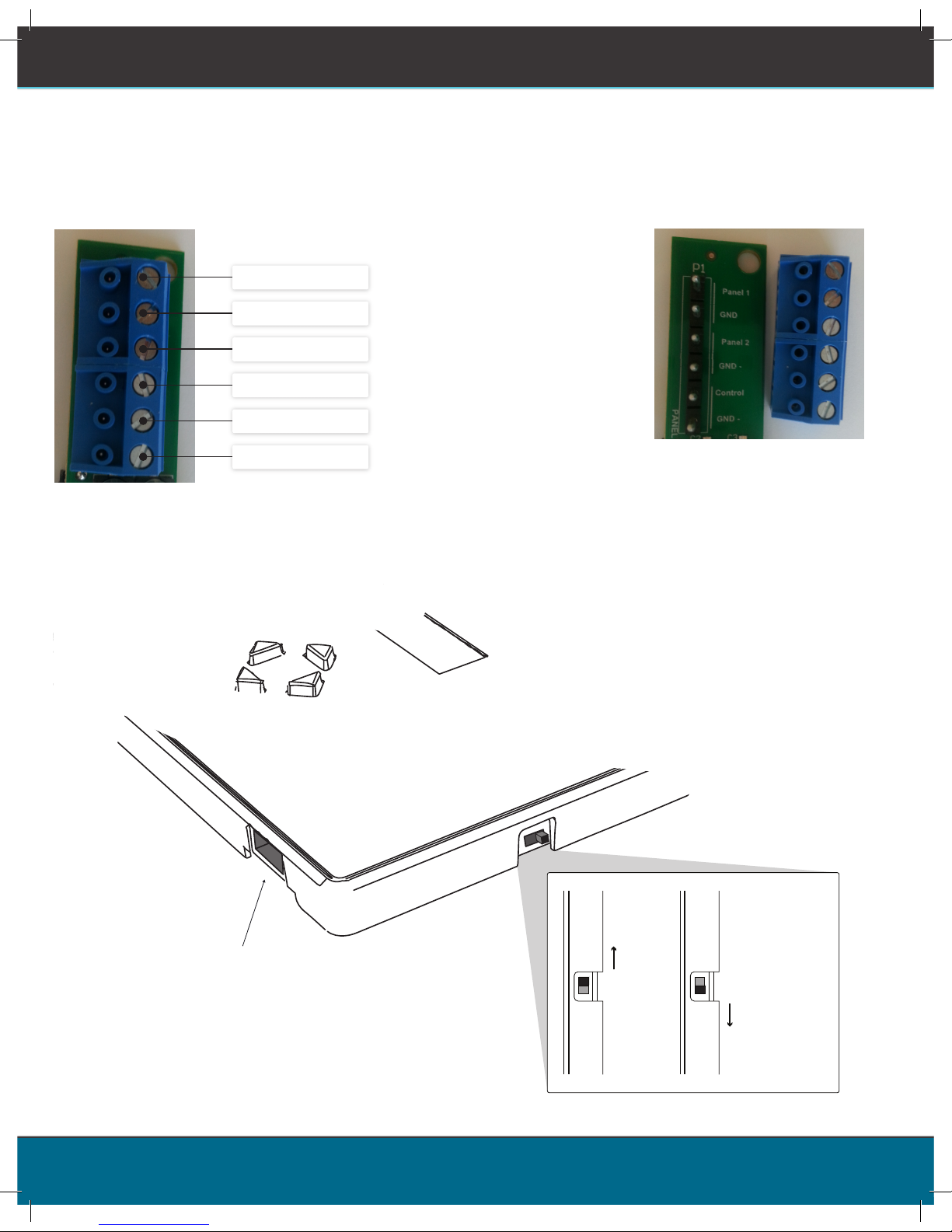
Note that the small switch on the side of the controller must be set to the “up” position (closer to the
top of the case) for the lights to work. The “down” setting enables the external USB jack, used for
rmware updates or for the optional Bluetooth dongle supplied with the Qt100 iPad app.
Connection to privacy signs
Run a separate cable from the controller mounting location to each lighting location. Do not daisy chain
signs as this may cause the lights to be of different brightness. Two 50 ft. (15.2m) plenum rated cables are
provided with the kit.
Sign 1 +
GND -
Sign 2 +
GND -
Control +
GND -
Note: Wiring nomenclature is
located under the removable
terminal block connector.
Page 8

page 15
Qt Conference Room Edition Installation and Operations Guide
INSTALLATION
Installing Qt Emitters
Important Considerations:
▪ Each run has a maximum of 60 emitters!
▪ Each run supports a maximum cable length of 1000 ft.
▪ Each home run cable attached to the control module should be labeled by Zone # and Run #.
Adding a logical name (e.g. Marketing, Private Ofces) is suggested. In addition, ll out “Zone
Destination Record” at the end of this Guide.
▪ The module has two identical outputs, Run 1 and Run 2. All emitters on Run 1 and Run 2 are
controlled equally.
▪ Each job-made cable should be manufactured according to ANSI/TIA/EIA Standard 568-B. See
custom cabling guidelines on page 16.
▪ Before installation, job-made cables should be tested with a LAN cable tester.
Installation:
1. Set the masking output level to the maximum level of 30.
2. Refer to the emitter layout and wiring diagram provided by the dealer for cable run connections.
3. Run home run cables from control module to the location of the rst emitter for all runs.
4. Gather all ceiling tiles (per layout drawing) that are to receive emitters. Use the supplied hole saw
to cut holes in designated tiles. Cut all tiles from the front. (Different types of emitter housings are
available to attach in areas where there are no suspended ceiling tiles.)
5. Push the emitter through the front of the hole in tile and secure it by pushing down and twisting the
locking ring at the back of the emitter.
6. Connect a run cable from the specied OUTPUT jack on the module to the INPUT jack of the rst
emitter. Listen to each emitter as it is connected. If you cannot hear its “whooshing” sound:
a. Try a different emitter.
b. Test all four previous cables for continuity and shorts. Repair any faulty cables.
c. If a short is detected, the masking will shut off until the short is physically xed. The error on the
control module will remain until the error is cleared. (see Clearing Error Codes, page 31) Set the
masking output level to the maximum level of 30.
7. Connect the next OUTPUT cable to the emitter OUTPUT jack.
Note:
▪ The “tombstone” hook on the back of each emitter is next to the INPUT jack.
This can help you nd the INPUT jack by touch.
▪ To adjust for unexpected obstacles such as sprinkler heads, each emitter may
be moved up to 2 ft. (one tile or 0.6 m) in any direction, if necessary.
Page 9

page 16
Qt Conference Room Edition Installation and Operations Guide
INSTALLATION
8. Run the cable to next designated tile specied on emitter layout and wiring diagram. Tie cables up
to structure or suspend from deck as required by local building code.
9. On the next emitter, connect this cable to the INPUT jack.
10. Repeat Steps 4 through 9 for the remaining emitters on the home run.
Set sound masking volume levels using either the front panel controls.
DO NOT put the input cable into the output port of the emitter. If sound is only heard by putting the
cable in the output, there is a problem earlier in the cable run. Be sure to x any problems and hear the
“whooshing” sound before installing the next emitter.
The input jack of each emitter bears this symbol
and is located near the safety tie off
The output jack of each emitter bears this symbol
Note:
Page 10

page 17
Qt Conference Room Edition Installation and Operations Guide
INSTALLATION
Custom Cabling Guidelines
Installing the controller and privacy signs
Important Considerations:
1. Use solid conductor 24 AWG CAT cable that meets local code requirements.
2. If the system is installed in a return air plenum, the cable must be plenum rated.
3. Shielding is not required. Unshielded twisted pair (UTP) cable is acceptable.
4. Snagless boots are not required.
5. RJ-45 plugs must use the “bent 3-tine” RJ 45 plugs intended for use with solid core CAT wire. Three
tine plugs can be purchased at a hardware store and from most CAT cable suppliers. DO NOT USE
the “aligned two-tine” type intended for stranded wire, as they provide improper contact and may
yield intermittent system operation. The diagram below shows the cross section view of both types.
6. Field test each cable after fabrication with the RJ-45 connectors (before nal installation), using
a standard network LAN cable tester, to check for continuity, shorts, and 1:1 (straight through)
connection.
Installation of the controller requires separating the front panel from the rear of the case – simply done
by pulling one from the other. All installation options require attaching the case rear rst, then getting
cables attached to the controller, then snapping the controller into place.
Controller Mounting Options
▪ Best practices: If installing the controller on a wall known to have sound transmission issues into an
adjacent space, it is recommended to use surface mounting. Be careful to seal airtight any cabling
holes to minimize sound transmission. Avoid back-to-back mounting of electrical or other wall
components within a single stud space.
▪ Best practices: On walls separating the conference room from an area with masking, don’t use
gang boxes with big holes as these are prone to passing sound. Whenever feasible, don’t install
the box on a wall requiring masking protection as it may exacerbate sound transmission problems
The controller may be mounted in several ways:
CORRECT
RJ-45 connector
with bent type
INCORRECT
RJ-45 connector
with aligned type
Page 11

page 18
Qt Conference Room Edition Installation and Operations Guide
INSTALLATION
Flush mount with supplied box
Cut hole in wall to dimensions x by x (use template) and run cables to this hole. After the cables have
been run to the hole in the wall, place the ush mount box in the wall (make sure up is actually up) and
snap the four clips that clamp to the back side of the drywall surface. Then attach the case rear to the
wall adapter. During installation if may be convenient to attach the wires to the tie-off point in the back
of the box to prevent the wires from falling back into the wall.
Controller
Case back panel
Flush mount box
3
3
/4” x 7 1/2” (95 x 190mm)
hole in wall
(See template on page 35)
4x control module
back panel screws
Page 12

page 19
Qt Conference Room Edition Installation and Operations Guide
Surface mount on a suitable 4-gang electrical box (3-gang using EU/UK hardware)
4-gang electrical box (pre-installed or retrotted) – after the cables have been run to the box, use four
supplied screws to attach the wall plate adapter. (In the case of EU 3-gang boxes, use M3 or M3.5 screws
as needed – these are not included.) Then attach the system back to the wall adapter.
Note: The wall plate adaptor is ABS plastic and may be painted to match wall color. Use a standard
spray primer (Krylon) before painting.
INSTALLATION
Wall plate adapter
4-gang NEMA wall box
or low voltage clip
(not included)
Wall hole
8x wall plate
adapter screws
Controller
Case back
panel
4x control module
back panel screws
Wall hole
Wall plate adapter
3-gang EU/UK wall box
(not included)
6 x screw
(not included)
Controller
Case back panel
4 x #6
self-threading
screw
Page 13

page 20
Qt Conference Room Edition Installation and Operations Guide
INSTALLATION
Surface mount directly to the wall
Surface or panel mount of back plate – either with cables through hole (if cables can be run through the
wall) or out the side to end up on the surface of the wall or mounting point. Mark holes with template,
open up larger holes for cables if desired, run cables, attach back plate.
The wires may be run out the back of the case rear, or to the sides using the available openings.
Consult a knowledgeable person about the best type of hardware to attach to your wall surface.
Installing the controller to the back plate.
After all cables have been attached, snap the controller in place.
After installation, the controller can be removed by pulling it, and it will snap away from its back,
exposing the cabling and also giving access to the mounting points.
Controller
Wall screws (not included)
Approximate hole locations
(use case back as template)
Page 14

page 21
Qt Conference Room Edition Installation and Operations Guide
INSTALLATION
Mounting options for the privacy signs
There are several options for mounting the privacy signs. These options allow for mounting on a variety
of wall surfaces, including glass.
1-gang box (North American NEMA or UK/EU types)
If using a 1-gang box, retrot or pre-installed, rst run cable to the box. Then mount the plate. Then
attach the cable. Then slide the sign down on the plate to secure it.
To remove, slide the light panel up and off the metal bracket.
Privacy sign
2x privacy
sign screws
Wall plate
1 gang NEMA wall
box or low voltage clip
(not included)
Wall hole
Privacy sign
2x privacy
sign screws
Wall plate
1 gang EU/UK wall box
(not included)
Wall hole
Page 15

page 22
Qt Conference Room Edition Installation and Operations Guide
Surface mount (double-sided tape), with cabling running through wall or on surface of wall.
If running a cable through the wall, get this into position rst. Note that the exit point for the cable on
the back of the sign is centered across the bottom
Connect the cable using the push terminals. Peel the double sided tape and attach the panel.
REMEMBER TO CHECK ALL CONNECTIONS AND CONFIRM PRIVACY SIGN OPERATION BEFORE ATTACHING TO WALL
INSTALLATION
Privacy sign
Self adhesive pad
Hole in wall for wire
(see template on page 37)
Page 16

page 23
Qt Conference Room Edition Installation and Operations Guide
INSTALLATION
Mounting on glass plus using “hider” plate for other side of glass surface
Best practices – it’s best to use self-adhesive tape, NOT a 1-gang box (because of sound transmission
issues).
If mounting the signs to either side of the same wall, don’t locate the boxes closer than 2 ft. from each
other.
Caution: The self-adhesive pads are very strong - take care in placing as moving after placement may be
difcult. Also note, special care may be required if mounting to glass with an adhesive lm coating.
Note: The hider plate is ABS plastic and may be painted to a desired color if needed. Use a standard
spray primer (Krylon) before painting.
Privacy sign
Self-adhesive pads
Wire
Glass surface
Hider plate
Self-adhesive pads
Page 17

page 34
Qt Conference Room Edition Installation and Operations Guide
ZONE DESTINATION RECORDS
Zone Destination Record
Zone 1 Run 1 Run 2
Settings Record
Volumes:
Zone: 1
Masking:
Input A:
Installation / Service:
Company name:
Install date:
Phone:
Page 18

page 35
Qt Conference Room Edition Installation and Operations Guide
4
7
/
16
in.
113mm
Hole cut outline
Flush mount box outline
Control module outline
8
5
/
16
in.
211mm
7
1
/
2
in.
190mm
3
3
/
4
in.
95mm
UP
Hole cut guide for flush mount box
Cut hole to 7
1
/
2
in. (190mm) by 3
3
/
4
in. (95mm)
HOLE CUT GUIDE FOR FLUSH MOUNT BOX
Page 19

page 36
Qt Conference Room Edition Installation and Operations Guide
Page 20

page 37
Qt Conference Room Edition Installation and Operations Guide
4 7/16 in.
113mm
Wire exit area
3 1/2 in.
90mm
Hole cut guide for privacy sign
Cut hole wire
1
/4 in (6mm) from lower edge of sign
Hole shape is not important, but be careful to stay
within area to be covered by sign.
REMEMBER TO CHECK ALL CONNECTIONS AND CONFIRM
PRIVACY SIGN OPERATION BEFORE ATTACHING TO WALL
HOLE CUT GUIDE FOR PRIVACY SIGN
Page 21

Cambridge Sound Management, Inc.
404 Wyman St. Suite 200
Waltham, MA 02451 USA
cambridgesound.com
© Copyright 2015 Cambridge Sound Management Inc. Quiet Technology, Qt, Cambridge Sound Management,
and the logo are trademarks of Cambridge Sound Management.
Page 22

This two page document is an addendum to the Qt® Conference
[Type a quote from the document or
the summary of an interesting point.
You can position the text box
anywhere in the document. Use the
Text Box Tools tab to change the
formatting of the pull quote text box.]
Panel 1
GND
Panel 2
GND -
Control
GND -
Room Edition manual. Please read.
NOTE: Below are supplemental images for the content contained on page
14 of the Qt® Conference Room Edition manual.
Connection to privacy signs
Run a separate cable from the controller mounting location to each lighting location. Do not
daisy chain signs as this may cause the light to be of different brightness. Two 50 ft. (15.2m)
plenum rated cables are provided with the kit.
Page 23

This two page document is an addendum to the Qt® Conference
Room Edition manual. Please read.
NOTE: Two new options have been added to the program menu of the
Qt® Conference Room Edition. These options are outlined below:
1. Contact Closure = Normal/Off or Normal/Low. When this option is set to “Normal/Off”,
the contact switch will toggle between Normal Volume (Contact Open) and Off (Contact
Closed). When this option is set to “Normal/Low”, the contact switch will toggle
between Normal Volume (Contact Open) and Low Volume (Contact Closed).
2. Disable OFF Button = On or Off. This option allows the user to disable the Off Button on
the front panel of the Qt-CRE.
 Loading...