

CAMBRIDGE qt 300, qt 600 Installation & Operation Manual
csmqt.com 800.219.8199
Qt™ 300/600
Installation & Operations Guide
page 2
1
2
3
Qt™ 300/600 Quick Installation Guide
page 3
4
5
6
For more information visit csmqt.com
or call 800.219.8199

page 4
Contents
Qt 300/600 Introduction
Hardware Installation
Installing the Control Module
Wall Mount
Rack Mount
Installing Qt Emitters
Emitter Installation Order
Installing Paging or Music to the Audio Inputs
Installing Contact Closures
Custom Cabling Guidelines
Battery Replacement
System Conguration (Front Panel and Monitor Control Software)
System Congurable Feature List (Front Panel / MCS)
Conguring the Control Module for the Network
IP Address DHCP
NETBIOS Support
Other Recommended Connections
Suggestions for Managing Multiple Control Modules
Front Panel Control
System Information
Setting Sound Masking Levels
Setting Audio Input Levels
Lock/Unlock the Front Panel
Congure Network Name and IP Address
Real-Time Clock or Network Clock
Reset System to Default Settings
System Control Using Monitor Control Software (MCS)
Connecting to the Qt 300/600 over Ethernet
MCS: Operation Section
6
8
8
8
9
10
10
12
12
13
14
15
15
16
16
16
16
16
17
17
18
20
20
21
21
21
22
22
23

page 5
Changing Masking Level Using MCS
Auto Ramping
Changing Input A and B Level
Time of Day Masking
Errors
MCS: Administration Section
Service
Zone Names
Networking and Security
Notication of Errors
Date and Time – Time Zone
Setting Equalizers and Emitter Fault Detection
MCS: Help
Links to Help Topics
Software Update
Documentation
MCS: Printout
Error Codes and Message
Post Installation Handoff
Warranty
Warranty
Settings Record
Homerun Zone Destination Record
24
24
25
26
27
27
28
28
28
28
29
30/31
33
33
33
34
34
34
36
37
38
39
40

page 6
Qt 300/600 Introduction
This manual discusses the installation of a sound masking system
using either the Qt 300 or the Qt 600. The Qt 300 and Qt 600
controllers have identical functionality, but different number of
zones supported - the Qt 300 supports 3 zones whereas the Qt 600
supports 6 zones. As you use this guide, remember the number of
zones and total area of coverage is the only real functional difference
between the systems. Collectively, the systems are referred to as
‘QtPro’ throughout this guide.
The Qt 600 supports six zones of sound masking, each with 1 to 120
emitters covering 100 to 12,000 square feet (9.3 m2 - 1,115 m2) per
zone. The Qt 300 supports three zones of sound masking, each with
1 to 120 emitters, covering up to 12,000 square feet per zone (1,115
m2). Each systems comes with two audio inputs which can be used
for paging and/or music. Additional controls for each zone include
time-of-day masking, auto ramping, self-monitoring fault detection
and notication, and independent equalizers for masking and audio
inputs. The system may be operated from its control module front
panel OR by a computer directly-connected to the module OR by
a computer connected through a local area network. See system
conguration on page 15.
It is important that the control module’s masking volumes be set
correctly for each zone to obtain the full effectiveness of the system.
If volumes are set too low, speech privacy will be reduced and work
place distractions will be much more apparent. If volumes are set too
high, the masking sound itself could become a source of distraction.
The higher the setting that can be used comfortably, the better the
acoustic privacy. For a given open ofce design, including ceiling
height, ceiling material and workstation panel height, we can dene
the masking volume required to achieve “normal acoustic privacy,”
i.e., when it is relatively easy to ignore surrounding conversations.
For a very large range of open ofce designs, the target level is
in the 45–48 dBA range, measured 3 ft. (0.9 m) above oor level.
Similarly, for private ofces, based on wall panel design and ceiling
construction, we can dene masking volumes required to achieve
“condential privacy,” i.e., conversations in adjacent ofces cannot
be understood. Most private ofces have a target level in the 38–42
dBA range, averaged spatially within the ofce.

page 7
Setting the masking volumes can be approached in one of two ways:
BEST: If a sound level meter is available, it is recommended that
the control module’s masking volumes be adjusted up or down to
achieve the following readings on the meter:
Private Ofce Zones
38-42 dBA, averaged spatially within the ofce
Open Area Zones
45-48 dBA, measured 3 ft. (0.9 m) above oor level
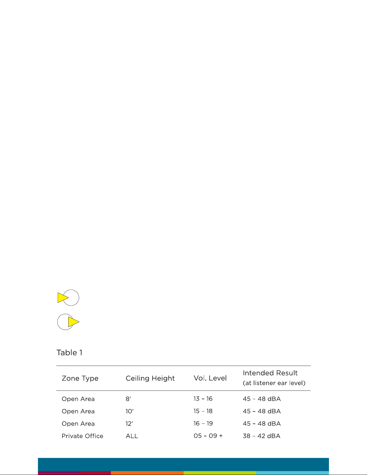
OTHERWISE: If a sound level meter is not available, the above levels
are likely to be achieved in most environments by setting the control
module’s masking volumes as follows:
Private Ofce Zones
05-09, for all ceiling heights
Open Area Zones
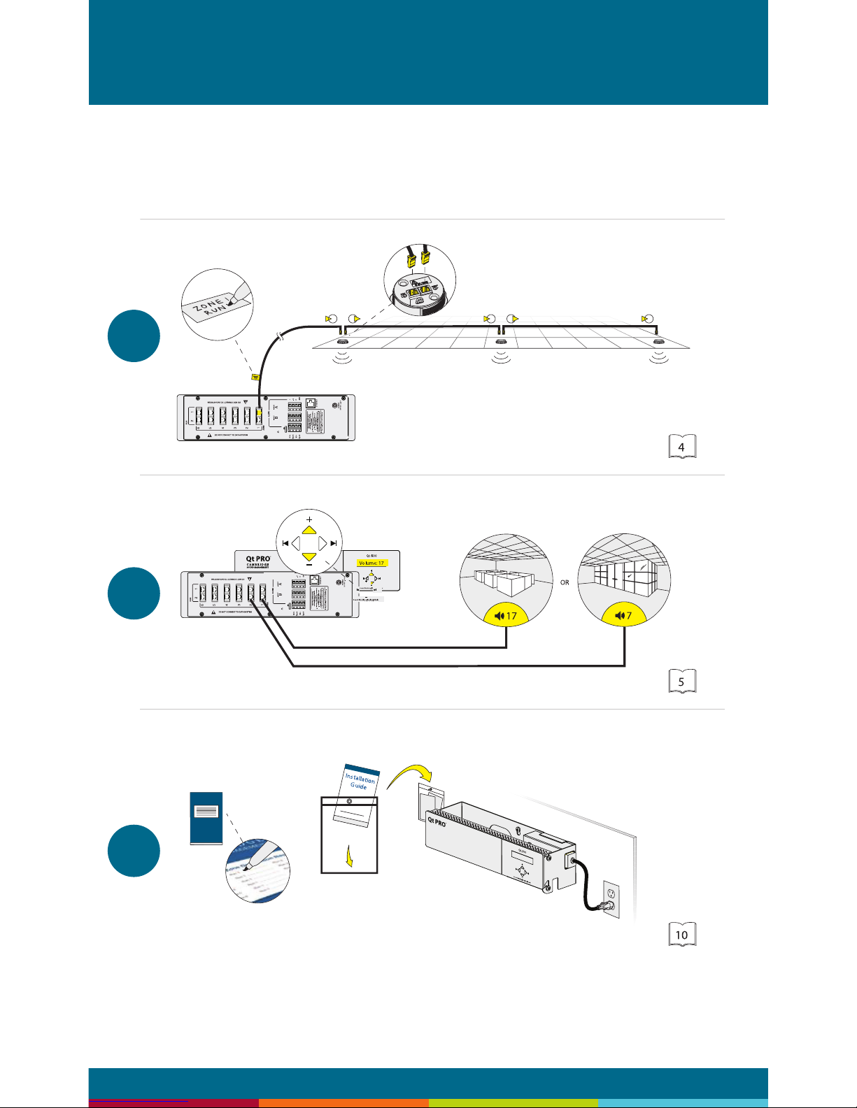
13-16, for 8 ft. (2.4 m) ceilings
15-18, for 10 ft. (3 m) ceilings
17-20, for 12 ft. (3.7 m) ceilings
Masking volumes must be set sufciently high to improve speech
privacy and reduce distraction but not so high that the masking
sound becomes objectionable. Settings within the above ranges
should accommodate both objectives. As a general rule, use the high
end of the range. Base nal settings on site conditions and customer
preferences. If people object to the sound level, set masking volumes
toward the bottom of the range or refer to the ‘Ramping’ section of
this guide, found on page 24 for more information on introducing
masking into the space gradually. Remember that the effectiveness
of the system relies on sufcient masking sound level and that initial
objections are often overcome as people become accustomed to the
sound.
Different day and a night volumes may be set. The control module
ramps linearly between these two settings beginning at the time
specied and over the period of time specied. As the control
module ramps between settings, the current volume is displayed
under “Current.”
NOTE: This document uses the QtPro software version 6.0.0 for
feature conguration.
page 8
Qt 300/600 Introduction
Installing the Control Module
NOTE: Always plug/unplug power supply at wall outlet
NOTE: The Qt 600 is shown in the gures, but the Qt 300 installs in
the same manner.
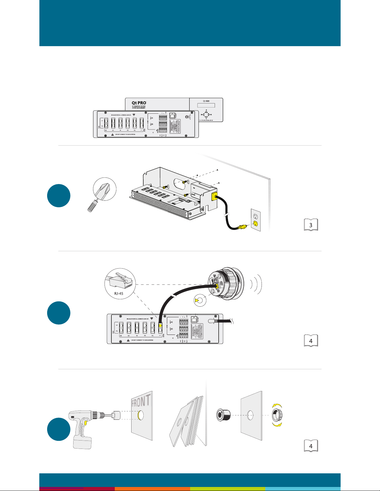
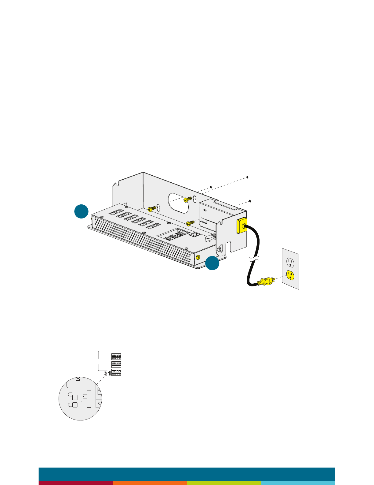
Wall Mount
Mount the bracket using the three screws and plastic anchors
(mollies) provided. Use a ¼ inch drill bit for the anchor hole. See
Figure 1.
Plastic anchors are #10-12 x 1¼ in. with #10 x 1½ screws.
NOTE: The control module hinges forward for wall mounting and
cable installation. To hinge forward, loosen screws A and B (see
Figure 1) used to secure the module during shipping.
Check to see that the panel lock switch is in the
UN-LOCKED position.
A
B
Figure 1
B3v
Bgnd
M3v
Mgnd
AUDI
O
+
-/LRGND
A
B
page 9
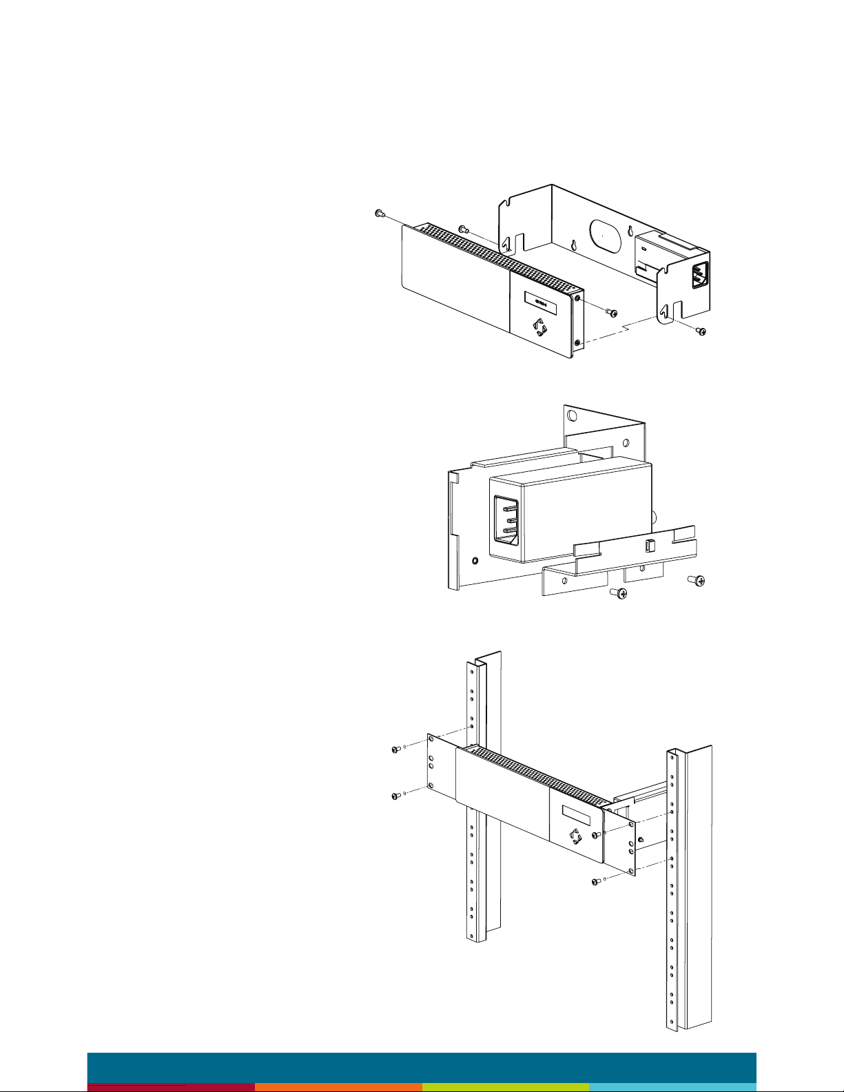
Rack Mount
Attach optional rack mount brackets to each end of the control
module.
NOTE: When rack mounted, the control module does not hinge
forward.
Step 1
Remove the QtPro and
power supply bracket from
wall mount bracket.
Step 2
Reassemble power supply
to right rack mount bracket
using 6:32 black screws
(included with bracket).
Step 3
Fasten left and right rack
mount brackets to QtPro
using the screws removed in
Step 1.
Step 4
Mount QtPro to 19” cabinet
rail using 10:32 screws
as shown (included with
bracket).
A
B
B

page 10
Installing the Qt Emitters
Important Considerations:
▪ Each run has a maximum of 60 emitters
▪ Each run should have a maximum length of 1000 ft. (305 m).
▪ Each home run cable attached to the control module should
be labeled by zone # and run #. Adding a logical name (e.g.
Marketing, Private Ofces) is suggested. In addition, ll out
“Home Run Zone Destination Record” at the end of this Guide.
▪ Each zone has two identical outputs, run 1 and run 2. All
emitters on run 1 and run 2 are controlled equally for each zone.
▪ Each job-made cable should be manufactured according to
ANSI/ TIA/EIA Standard 568-B. See custom cabling guidelines
on page 13.
▪ Job-made cables should be tested with a LAN tester before
installation. Adjustable emitters should be set for lower sound
levels, within a zone, when sound level measurements show an
acoustically loud subsection.
Emitter Installation Order
1. Set the masking output level of all zones to level 20.
2. Refer to the emitter layout and wiring diagram provided by the
dealer for cable run connections by zone.
3. Run home run cables from control module to the location of the
rst emitter for all runs in all zones.
4. Gather all ceiling tiles (per layout drawing) that are to receive
emitters. Use the supplied hole saw to cut holes in designated
tiles. Cut all tiles from the front. (Different types of emitter
housings are available to attach in areas where there are no
suspended ceiling tiles.)
5. Push the emitter through the front of the hole in tile and secure
it by pushing down and twisting the locking ring at the back of
the emitter.
6. Connect a run cable from the specied zone OUTPUT jack on
the module to the INPUT jack of the rst emitter. Listen to each
emitter as it is connected. If you cannot hear its “whooshing”
sound:
a. Try a different emitter.
b. Test all four previous cables for continuity and shorts.
Repair any faulty cables.
c. If there is a short, masking volume will shut off. The
short should clear itself in approximately ve minutes.
If it does not, power cycle (unplug and re-plug) the
control module.
page 11
NOTE: The “tombstone” hook on the back of each emitter is next to
the INPUT jack. This can help you nd the INPUT jack by touch.
NOTE: To adjust for unexpected obstacles such as sprinkler heads,
each emitter may be moved up to two feet (one tile) in any direction,
if necessary.
7. Connect the next OUTPUT cable to the emitter OUTPUT jack.
8. Run the cable to next designated tile specied on emitter layout
and wiring diagram. Tie cables up to structure or suspend from
deck as required by local building code.
9. On the next emitter, connect this cable to the INPUT jack.
10. Repeat Steps 4 through 9 for the remaining emitters on the
home run.
11. Set sound masking volume levels for each zone, using either the
front panel controls or the software interface. Set sound levels
according to Table 1.
12. If a small area within a zone exhibits a perceived volume louder
than the rest of the zone, use the adjustable emitter toggle
switches to turn the volume down for the emitters in that area.
Emitters can decrease volume by 3,6 or 9 dB. See emitter spec
sheet for more details.
Be sure to x any problems and hear the “whooshing” sound before
installing the next emitter. If necessary see the Errors section of this
guide, found on page 27.
Note:
The input jack of each emitter bears this symbol
and is located near the safety tie off
The output jack of each emitter bears this symbol

page 12
Installing Paging or Music to the Audio Inputs
1. Be sure power is OFF by unplugging power cord from wall
outlet.
2. Balanced Audio Input: (most often, but not always characteristic
of paging systems.) Connect signal wires to + and - at input A or
B. Connect the shield to GND at the audio source.
3. Unbalanced Audio Input: (typical of music systems.)
a. Mono Signals: Connect signal wire to both L and R at
input A or B. Connect the ground wire to GND.
b. Stereo Signals: Connect signal wires to L and R at
input A or B. Connect the ground wire to GND.
4. If a music source is to be connected, using Input B allows
emergency music shut-off. See Contact Closures below.
Installing Contact Closures
The QtPro provides an instant shut-off capability for masking and/ or
audio Input B if connected to a contact closure interface. The contact
closure utilizes the same style connector as audio Inputs A and B (4pin).
To leverage this feature for masking, connect a two-conductor cable
to the two connectors, labeled M3V and MGND. To leverage this
feature for Audio Input B, connect a two-conductor cable to the two
connectors, labeled B3V and BGND.
The other end of these conductors (treated as pairs/circuits) can be
terminated on closure mechanisms of choice.
1. To shut off masking, form a connection between the two “M”
conductors.
2. To resume masking, break the connection (Don’t break the
connectors as you may want to reuse them).
The contact closure for audio Input B follows the same logic.
 Loading...