

CAMBRIDGE M-SERIES Technical Manual
M-SERIES
DRAW THRU
DIRECT GAS-FIRED
MAKE-UP AIR HEATERS
TECHNICAL MANUAL
mWARNING:
Improper installation, adjustment, alteration, service or maintenance can cause property damage, injury or death. Read the installation, operating, and maintenance instructions thoroughly
before installing or servicing this equipment.
FOR YOUR SAFETY
The use and storage of gasoline or other flammable vapors and liquids in open containers in
the vicinity of this appliance is hazardous.
ASHRAE
FOR YOUR SAFETY
If you smell gas:
1. Open windows.
2. Don’t touch electrical switches.
3. Extinguish any open flame.
4. Immediately call your gas supplier.
Made in the USA
ASHRAE
90.1
COMPLIANT
COMPLIANT
®
®
M-TM1-0915
M110-M115 (3HP) REV. G
M115 (5HP) REV. H
M118-M136 REV. C
M140 REV. A

LIMITED WARRANTY
Cambridge Engineering, Inc. (“Manufacturer”) warrants its products (“the Products”) to be free from
defects in material and workmanship. Manufacturer’s M-Series Products shall be warranted for a period of
twenty-four (24) months from the date of shipment, except that burner assemblies are warranted for
five (5) years from date of shipment.
Buyer’s sole and exclusive remedy for any nonconformity with this warranty shall be, at Manufacturer’s
option, repair or replacement of nonconforming parts, provided that Buyer shall return to Manufacturer, shipping
prepaid, said nonconforming part(s) bearing a durable tag indicating the Serial Number of the Product
from which the part was taken. In addition, Manufacturer may opt not to repair or replace nonconforming
Product or part(s), but instead may refund to Buyer the price thereof, in lieu of repair or replacement. In no
event shall Manufacturer be liable for more than a refund of the purchase price or replacement value of the
Product or part(s), whichever is less. This Warranty does not apply to field labor charges.
This Warranty does not apply and shall be void as to any Products that are misused or misapplied, that are
installed, operated or maintained not in conformity with Manufacturer’s design, specifications, instructions, or Technical Manual, or are installed, operated or maintained in violation of any applicable national
or local codes or industry standards.
Manufacturer does not warrant Products if they are abused, improperly operated or maintained, subjected
to abnormal wear and tear, damaged due to improper gas or electric service, damaged in transit, or that
have been repaired or modified by others without Manufacturer’s written authorization.
Buyer shall have no right to enforce this Warranty unless it has complied with all of its obligations under
the contract for purchase/lease of the Products, including without limitation being current on all payment
terms.
THIS LIMITED WARRANTY IS MANUFACTURER’S ONLY WARRANTY WITH RESPECT
TO THE PRODUCTS, AND IT IS IN LIEU OF AND SUPERSEDES ANY AND ALL OTHER
WARRANTIES OF ANY KIND WHATSOEVER, WHETHER WRITTEN, ORAL OR IMPLIED,
INCLUDING WITHOUT LIMITATION ANY IMPLIED WARRANTIES OF MERCHANTABILITY OR
FITNESS FOR A PARTICULAR PURPOSE. THE REMEDIES AFFORDED BUYER BY THIS WARRANTY
ARE THE ONLY REMEDIES AFFORDED BUYER FOR ANY NONCONFORMITY WITH THIS
WARRANTY OR FOR ANY DEFECT IN PRODUCTS, SERVICES, OR REPRESENTATIONS
PROVIDED BY MANUFACTURER IN CONNECTION WITH SUCH PRODUCTS. IN NO EVENT
SHALL MANUFACTURER BEAR ANY LIABILITY FOR INCIDENTAL OR CONSEQUENTIAL
DAMAGES OF ANY KIND WHATSOEVER, INCLUDING WITHOUT LIMITATION PERSONAL
INJURY (INCLUDING DEATH), PROPERTY DAMAGE, LOST PROFITS OR OTHER ECONOMIC
LOSS.
Buyer acknowledges that the foregoing warranty, limitations, and exclusions are a reasonable allocation
of commercial risks by and among sophisticated business entities and are not subject to dispute as to their
commercial reasonableness, fairness or ability to satisfy the essential purposes of the parties’ transaction.

M-SERIES
TECHNICAL MANUAL
Contents
Hazard Summary .............................................................................................................. 2
Typical System Overview
Accessory Identication .................................................................................................. 4
Heater / Accessory Weights ............................................................................................5
Heater Operation ............................................................................................................. 6
Heater Conguration
Installation Instructions
Uncrating Instructions
Mounting Location
Horizontal Mount - Mounting Curb ................................................................................ 8
Horizontal Mount - Roof Top Conguration .................................................................. 9
Horizontal Mount - Outdoor Pad Mount Conguration ...............................................13
Horizontal Mount - Thru Wall Conguration ...............................................................16
Vertical Mount - Outdoor Conguration ....................................................................... 19
Vertical Mount - Indoor Conguration .........................................................................23
Gas Piping ..................................................................................................................... 26
Electrical .......................................................................................................................27
Start-Up Instructions ....................................................................................................... 28
Operating Instructions ..................................................................................................... 35
Operating Sequence ......................................................................................................35
Electronic Thermostat ................................................................................................... 36
TSS Controller ..............................................................................................................38
Maintenance Instructions ................................................................................................ 47
Reference ........................................................................................................................ 48
Heater Roof and Wall Openings ...................................................................................48
Heater Discharge Dimensions .......................................................................................48
Gas Train Drawings ......................................................................................................49
Electrical Control Enclosure Isometric Drawing ......................................................... 55
Electrical Wiring Diagrams ........................................................................................... 58
Connection Diagram ..................................................................................................... 64
Gas Control Systems ..................................................................................................... 65
Remote Control Station Components ........................................................................... 65
Individual Heater Component Descriptions .................................................................. 66
Damper Motor Replacement & Adjustment ................................................................. 70
Troubleshooting Guide..................................................................................................73
ANSI/ASHRAE/IESNA Standard 90.1 ..........................................................................79
Maintenance Log ............................................................................................................ 80
................................................................................................. 3
....................................................................................................... 6
..................................................................................................... 7
..........................................................................................................7
Copyright 2015
Cambridge Engineering, Inc.
All Rights Reserved
Cambridge Engineering, Inc.
760 Long Road Crossing Dr.
Chesterfield, MO. 63005
Phone: (636) 532-2233, Fax: (636) 530-6133
www.cambridge-eng.com

HAZARD SUMMARY
Hazard Identification
Warnings and Cautions appear at appropriate sections throughout this manual. Read these carefully.
mWARNING: Indicates a potentially hazardous situation which could result in
death or serious injury.
mCAUTION: Indicates a potentially hazardous situation which may result in
minor or moderate injury. It may also be used to alert against
unsafe practices.
CAUTION: Indicates a situation that may result in accidents with equipment or
property damage only.
The following safety precautions apply to the installation, operation, and maintenance of the equipment
described by this technical manual.
mWARNING:
Any unauthorized modification of this equipment
shall void the warranty.
mWARNING:
Only qualified personnel should attempt installation, service, and repair of this equipment. Use
extreme caution and observe safety regulations at
all times.
mWARNING:
Recirculation of room air is not permitted.
Adequate building relief shall be provided so as to not
over-pressurize the building when the make-up air heating system is operating at its rated capacity. It should be
noted that this can be accomplished by taking into
account, through standard engineering methods, the
structure’s designed infiltration rate, by providing properly sized relief openings, by interlocking a powered
exhaust system, or by a combination of these methods.
when the heater is providing the make-up air to a boiler
room), the heater is to be interlocked to open inlet air
dampers or other such devices.
If the heater is installed such that an inlet duct is utilized, the duct system must be purged with at least four
air changes prior to an ignition attempt.
IMPORTANT
Installation in Aircraft Hangars
Refer to the Standard for Aircraft Hangars, ANSI/
NFPA 409, for specific information on the installation
requirements for these heaters in airplane hangars.
IMPORTANT
Installation in Parking Garages
Refer to the Standard for Parking Structures, ANSI/
NFPA 88A, or the Standard for Repair Garages, ANSI/
NFPA 88B, for specific information on the installation
requirements for these heaters in public garages.
If in doubt regarding installation or application,
contact Cambridge Engineering Customer Service
Group at 800-473-4569 during the hours of 8:00 a.m.
to 5:00 p.m. Central Time, Monday through Friday.
If the failure or malfunction of this heater creates a hazard to other fuel burning equipment in the building (e.g.
Cambridge Engineering, Inc. 2 M-Series Technical Manual

TYPICAL SYSTEM OVERVIEW
CONTROL SYSTEMS:
MAXITROL SERIES 14
The Maxitrol Series 14 electronic discharge temperature
control system maintains a constant discharge temperature. The standard control permits manual adjustment
of discharge temperature (55° to 90°F) from inside the
heater control enclosure. As an option, a Remote Heat
Adjust control with override capability to 130°F can be
provided to allow manual adjustment of discharge temperature (55° to 130°F) from either inside the heater con-
trol enclosure or in the Remote Control Station.
MAXITROL SERIES 14 WITH SPACE
THERMOSTAT
The Maxitrol Series 14 modulation controls function as
described above using the optional Remote Heat Adjust
control in conjunction with an electronic space thermostat switch contact to increase discharge temperature.
The discharge temperature will increase to a preset rise
(0°F to 40°F) above the set point on the Remote Heat
Adjust control face based on the setting of the override
temperature dial, which is visible from the top of the
control.
MAXITROL SERIES 44
The Maxitrol Series 44 modulation controls maintain
a constant space temperature by increasing or decreasing the discharge temperature. The Space Temperature
Selector is set to maintain the space temperature of the
heated space by controlling the heater output between
the MIN and MAX setting on the amplifier. The MIN
dial setting determines the minimum discharge temperature the heater will deliver (40°F to 80°F). The MAX dial
setting determines the maximum discharge temperature
the heater will deliver (80°F to 140°F).
MAXITROL SERIES 44 / TAMPER PROOF
The Maxitrol Series 44 / Tamper Proof temperature
control system is similar to the Maxitrol Series 44 controls above except the adjustable Space Temperature
Selector control is replaced by two other controls. The
adjustable portion of the temperature selector is typically
mounted in the Remote Control Station to prevent unwanted
tampering of the temperature setting and the non-adjustable
space sensor is mounted in the space being heated.
M-Series Technical Manual 3 Cambridge Engineering, Inc.
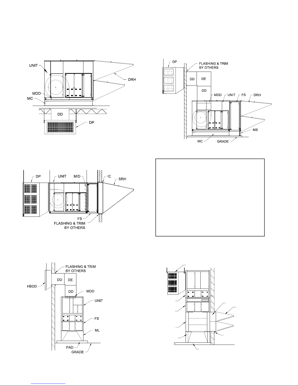
TYPICAL SYSTEM OVERVIEW
FLOOR
ACCESSORY IDENTIFICATION
Horizontal Mount
Roof Top Configuration
Horizontal Mount
Thru Wall Configuration
(Not applicable to M140)
Horizontal Mount
Outdoor Pad Mount Configuration
Component Identification
DD Discharge Duct
DE Discharge Elbow
DP Discharge Plenum
DRH Dual Rainhood w/ Inlet Screen & Filter Rack
FS Filter Section V-Bank
FSID V-Bank Filter Section/Inlet Damper Combo
HBDD Horizontal Blast Discharge Diffuser
IC Inlet Collar
IE Inlet Elbow
MC Mounting Curb
MDD Motorized Discharge Damper
MID Motorized Inlet Damper
ML Mounting Legs
SRH Single Rainhood w/ Inlet Screen
Vertical Mount
Outdoor Configuration
Cambridge Engineering, Inc. 4 M-Series Technical Manual
UNIT
FSID
Vertical Mount
Indoor Configuration
DP
IE
ML
IC
DRH
FLASHING & TRIM
BY OTHERS

HEATER / ACCESSORY WEIGHTS
Horizontal Mount (Weights Shown In Pounds)
Model M110 M112 M115
Base Heater
Rain Hood - Single
Rain Hood - Dual, Upper
Rain Hood - Dual, Lower
Filters for Rain Hood
Inlet Screen
Inlet Collar
Inlet Damper (internal)
V-Bank Filter Section
Discharge Duct - 20"
425 440 550 1125 1395 2045 2475 2845 5345*
45 45 70 135 175 275 325 375 N/A
N/A N/A N/A 95 145 240 270 325 480
N/A N/A N/A 75 105 170 205 280 410
10 10 15 20 30 45 60 80 90
5 5 10 10 15 25 35 40 45
40 40 50 85 110 170 200 230 335
25 25 35 55 65 125 155 210 290
70 70 100 215 235 285 400 500
M118 M120 M125 M130 M136 M140
**
Discharge Duct - 50"
Discharge Duct - 72"
Discharge Damper (internal)
Discharge Plenum 4-way
Discharge Plenum 3-way
Discharge Splash Pan
Curb 14"
Curb 24"
60 70 80 90 120 140 160 180 200
70 85 95 125 150 180 220 250 280
N/A N/A N/A 30 30 35 45 55 75
100 150 200 250 300 400 470 930 1480
80 130 175 220 260 360 430 500 795
40 40 40 60 60 60 80 80 80
60 70 80 100 120 180 210 230 270
100 120 140 170 200 270 310 340 445
*Due to shipping constraints the M140 consists of a of blower module (3625 lbs.) and burner module (1720 lbs.)
**Consult Factory
Vertical Mount (Weights Shown In Pounds)
Model
Base Heater
Rain Hood - Single
Rain Hood - Dual, Upper
Rain Hood - Dual, Lower
Filters for Rain Hood
Inlet Collar
Inlet Elbow
Inlet Damper
V-Bank Filter Section
Filter Section/Inlet Damper Combo
Discharge Duct - 20"
Discharge Duct - 50"
Discharge Duct - 72"
Discharge Damper (internal)
Discharge Elbow
Discharge Plenum 3-way w/enclosure
Discharge Diffuser
Mounting Legs 3-foot, set of 4
Mounting Legs 5-foot, set of 4
M118 M120 M125 M130 M136
1800 2300 2900 3200 3600
105 165 285 395 485
80 120 210 290 345
55 90 150 210 275
20 30 45 60 80
80 110 170 200 230
450 500 780 1040 1175
305 345 400 475 490
280 380 420 555 715
470 600 670 860 920
90 120 140 160 180
125 150 180 220 250
35 35 40 60 75
95 120 170 230 340
280 320 420 510 580
210 230 280 310 350
250 250 250 250 250
400 400 400 400 400
M-Series Technical Manual 5 Cambridge Engineering, Inc.
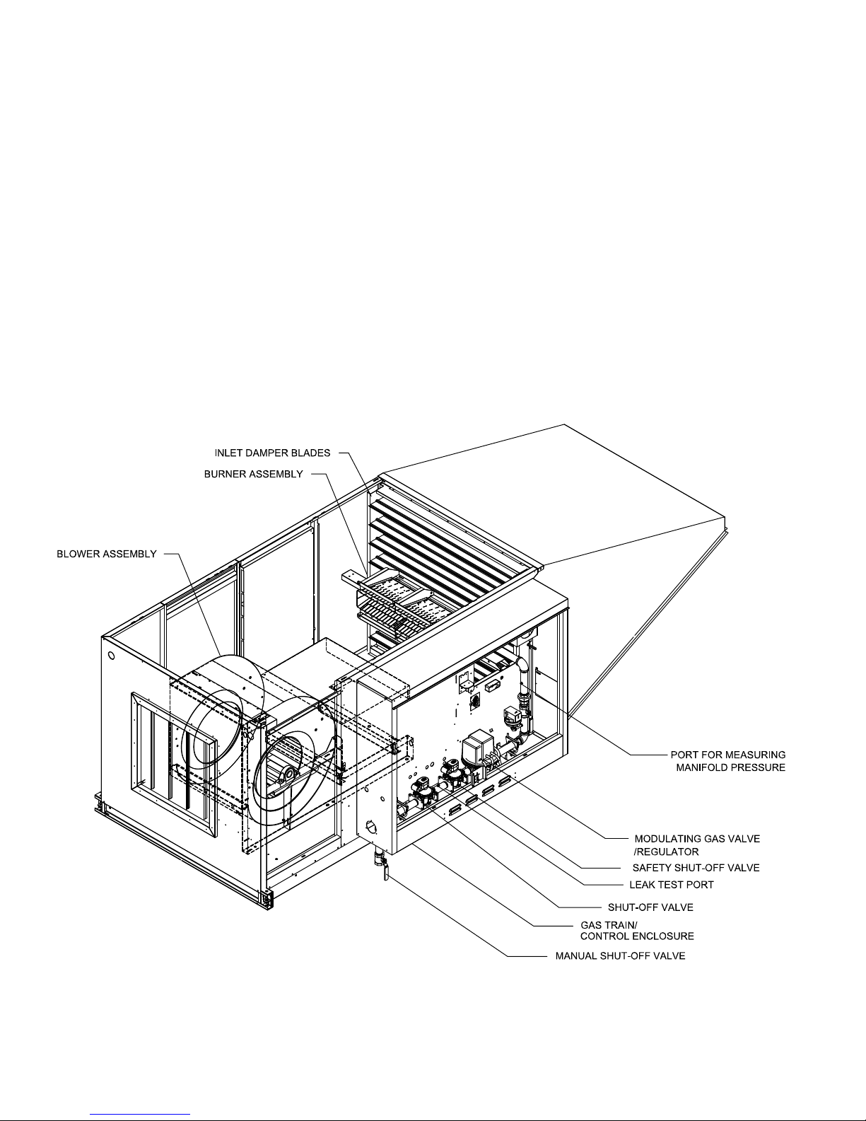
TYPICAL SYSTEM OVERVIEW
HEATER OPERATION
Cambridge M-Series Draw-Thru heaters provide
fresh air ventilation to a facility, provide tempered air
to replace the air that is mechanically exhausted, or
address cold drafts from natural infiltration. Heater
operation is typically electrically interlocked with
mechanical exhaust fans, manually operated switches,
HEATER CONFIGURATION
programmable timers, or other process control systems. The discharge temperature of heaters with fixed
discharge temperature controls is typically set 10°F to
20°F above the desired space temperature. The entering air thermostat acts as an economizer by deactivating burner operation during mild weather.
Cambridge Engineering, Inc. 6 M-Series Technical Manual

INSTALLATION INSTRUCTIONS
UNCRATING INSTRUCTIONS
1. Verify the number of items on the Bill of Lading
versus the number of items received.
IMPORTANT
Field constructed intake accessories should be designed to minimize the entry of snow
and rain.
2. Check for shipping damage. If damage is found,
immediately file a claim with carrier before
proceeding further.
3. Check items received to make sure they agree with
ordering information including verification of data
on the make-up air heater nameplate.
IMPORTANT
Do not discard any components or accessories.
MOUNTING LOCATION
Verify feasibility of the installation location selected
with respect to accessibility to the heater for service
and maintenance functions. Ensure the positioning of
the heater does not inhibit fork truck operation, storage rack access, or other operations within the facility.
Ensure the heater inlet and outlet are not blocked or
severely restricted, such that it would affect the rated
airflow through the heater or affect the desired air distribution pattern of the heater. If upon review of the
proposed installation, a problem is discovered which
may be considered detrimental to the performance of
the heater, or restricts its serviceability, or deviates from
the instructions or drawings which may be provided, it
is the responsibility of the installer to communicate that
information to the person or persons responsible for providing the installation instructions or drawings prior to
proceeding with the installation.
IMPORTANT
Minimum clearance from the face of the electrical control enclosure to surrounding grounded surfaces for
service activities is 42". Adequate clearance for burner
removal is also required, which is based on 42" or
the length of the burner + 12", whichever is greater.
Access for service functions is also required on the opposite side of the make-up air heater from the control
enclosure for a distance of 24".
mWARNING:
Where the mounting height of the heater is
required to be above 15 feet, work platforms or
service lifts should be provided for accessibility to the equipment for service and maintenance
activities.
M-Series Technical Manual 7 Cambridge Engineering, Inc.
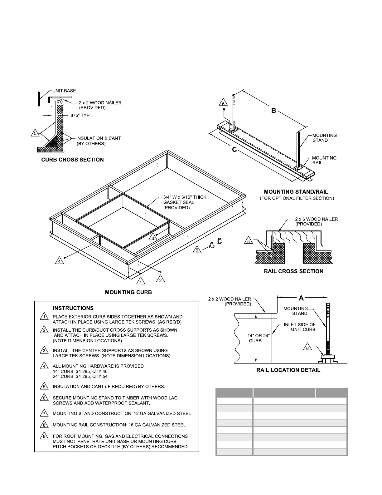
INSTALLATION INSTRUCTIONS
HORIZONTAL MOUNT - MOUNTING CURB
M110 - M136
(Shown for Roof Top Configuration - Downblast Application)
Cambridge Engineering, Inc. 8 M-Series Technical Manual
Model A B C
M110
M112
M115
M118
M120
M125
M130
M136
32.38" 27.12" 48"
32.38" 27.12" 48"
32.38" 40.31" 60"
32.38" 44.10" 60"
32.38" 50.26" 72"
37.88" 63.12" 84"
37.63" 84.81" 96"
37.88" 84.81" 96"

INSTALLATION INSTRUCTIONS
HORIZONTAL MOUNT - ROOF TOP CONFIGURATION
mWARNING:
Due to the size and weight of this equipment, it is
recommended that the heater support structure be
reviewed and approved by a qualified structural engineer and the roof manufacturer before installing this
equipment.
IMPORTANT
Before proceeding with the installation, verify the feasibility of the location selected with respect to accessibility to the equipment for service and maintenance
functions.
IMPORTANT
To minimize snow and rain ingestion, position the heater inlet opposite the prevailing wind.
mCAUTION:
To prevent contaminated air from being drawn into
the heater, install the heater’s inlet at least 10 feet
from any building exhaust, process exhaust, sewer
stacks, or other sources that would allow contaminants to be drawn into the heater. Consult local
codes for applicable building code provisions for
ventilation air.
IMPORTANT
For model M140 heaters, refer to the “Field Assembly
Instructions” worksheets included with this manual for
detailed heater assembly directions.
IMPORTANT
The roof curb or support structure should be installed such that the heater will sit level. Cambridge
Engineering recommends mounting the heater 24" off
the roof surface in areas where snow accumulation
could impact heater operation.
3. Lower the discharge duct through the roof opening.
4. Install the roof curb gasket.
5. Use a crane or comparable lifting device to raise
and position the equipment. Block the heater where
necessary. Use a spreader bar to prevent damage and
connect slings to the lifting eyes.
6. Caulk all joints of the heater’s accessories installed
in the field. Use a clear or gray latex based polyurethane caulking to prevent water leaks.
7. Seal all roof penetrations to prevent roof leaks.
8. Install the discharge plenum, where used, by screwing the plenum to the discharge duct. Install 4 hanging rods from the ceiling supports to the plenum’s
support brackets.
1. Prepare the roof for installation. (See pages 10-12
for roof opening dimensions for your specific
heater.) The gas and electrical connections must not
penetrate the unit base or mounting curb. Cambridge
Engineering recommends using pitch pockets or
decktite to seal the penetrations.
IMPORTANT
Accurate measurements are critical and will affect installation process.
2. Assemble and secure the roof curb to the support
structure per the recommendations of the structural
engineer and roof manufacturer.
M-Series Technical Manual 9 Cambridge Engineering, Inc.

TYPICAL INSTALLATION
HORIZONTAL MOUNT - ROOF TOP CONFIGURATION
M110 - M115
Roof Opening
Model W L
M110
M112
M115
19.25" 19.25"
20.75" 20.75"
23.5" 23.75"
Cambridge Engineering, Inc. 10 M-Series Technical Manual
Typical Curb and
Discharge Duct
Typical Curb and
Discharge Duct
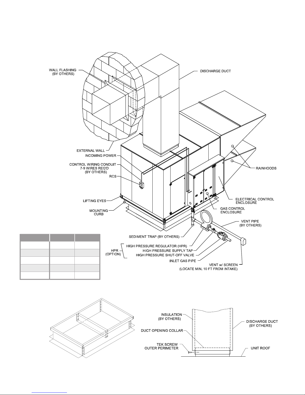
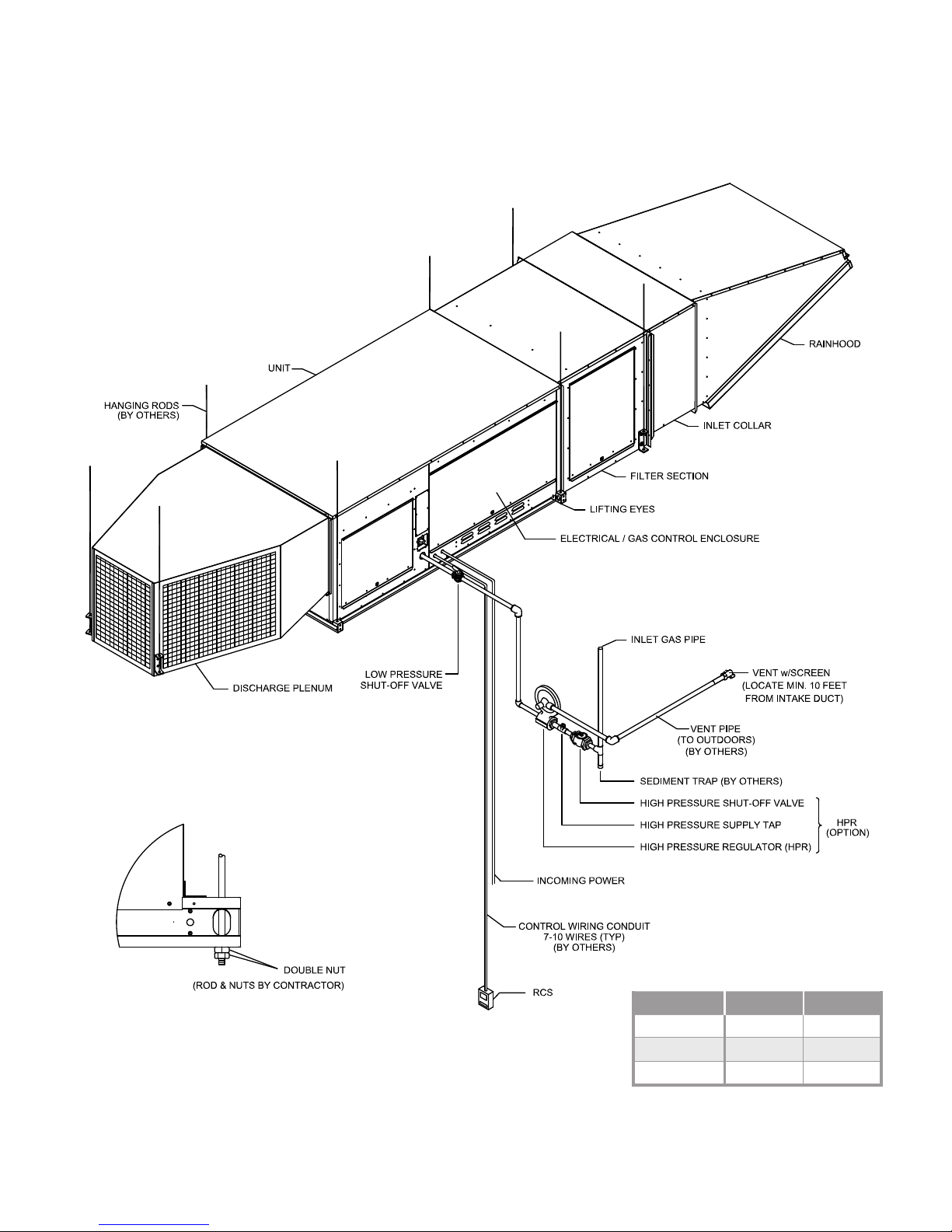
TYPICAL INSTALLATION
HORIZONTAL MOUNT - ROOF TOP CONFIGURATION
M118 - M136
GAS CONTROL
ENCLOSURE
RAINHOOD
LIFTING EYES
MOUNTING
CURB
DISCHARGE
HANGING
BRACKET
DUCT
DISCHARGE
PLENUM
INCOMING POWER
CONTROL WIRING CONDUIT
7-9 WIRES REQ'D
(BY OTHERS)
HIGH PRESSURE SUPPLY TAP
HIGH PRESSURE REGULATOR (HPR)
SEDIMENT TRAP (BY OTHERS)
RCS
ELECTRICAL CONTROL ENCLOSURE
VENT PIPE
(BY OTHERS)
VENT w/ SCREEN
(LOCATE MIN. 10 FT FROM INTAKE)
INLET GAS PIPE
HIGH PRESSURE SHUT-OFF VALVE
HPR
(OPTION)
Roof Opening
Model W L
M118
M120
M125
M130
M136
26.5" 26.5"
30.5" 30.5"
36" 36"
42" 42"
48" 48"
M-Series Technical Manual 11 Cambridge Engineering, Inc.
Typical Curb and
Discharge Duct
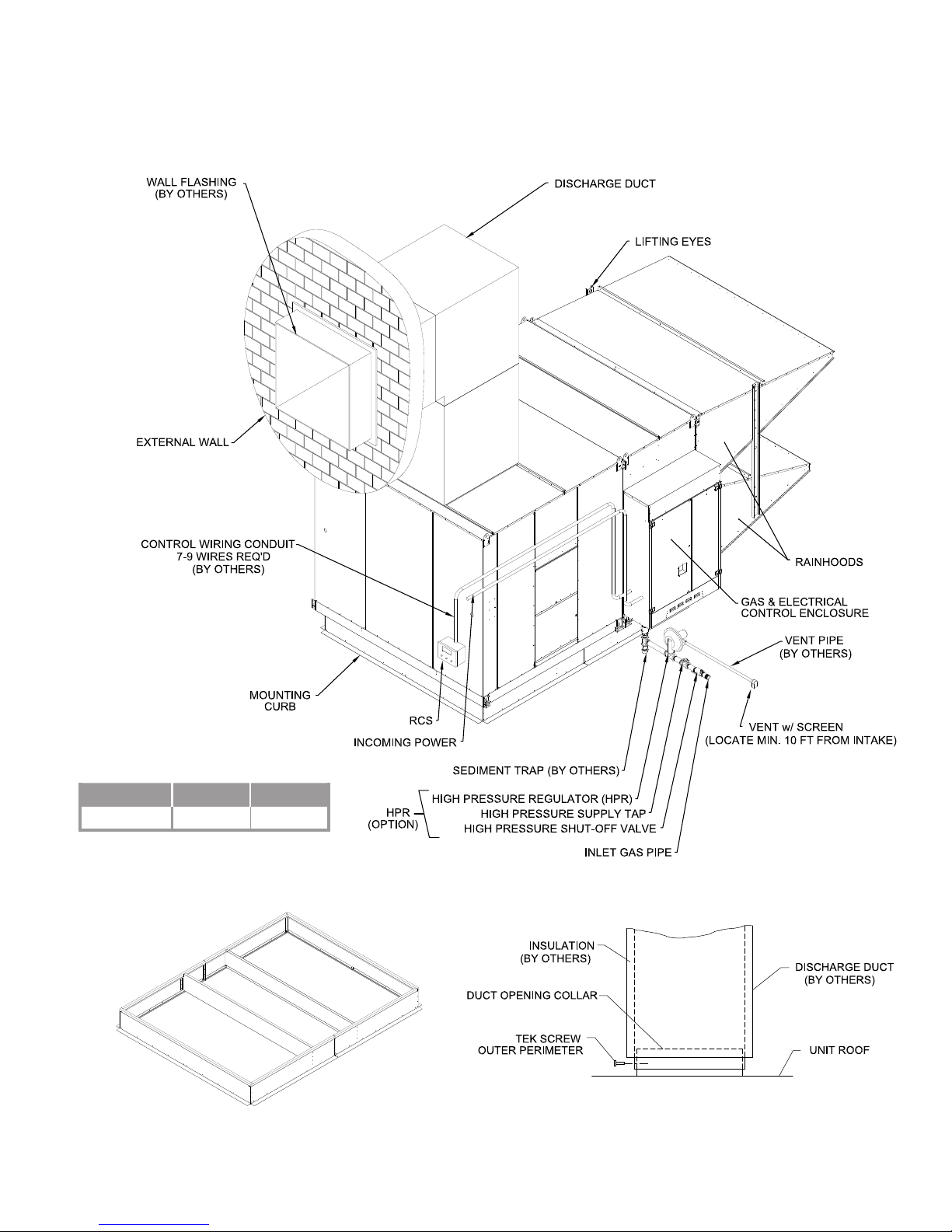
TYPICAL ROOF TOP INSTALLATION
TYPICAL INSTALLATION
HORIZONTAL MOUNT - ROOF TOP CONFIGURATION
M140
Lift Eyes
Rainhoods
Gas Control Enclosure
Vent Pipe (By Others)
Mounting Curb
Discharge Duct
Discharge Plenum
Hanger Bracket
Incoming Power
Control Wiring Conduit
7-9 Wires Req'd
(By Others)
RCS
Typical Curb and
Typical Curb and
Discharge Duct
Discharge Duct
Vent w/ Screen
(Locate Min 10 Ft from Intake)
Inlet Gas Pipe
High Pressure Shut-off Valve
High Pressure Supply Tap
High Pressure Regulator (HPR)
Sediment Trap (By Others)
HPR
(Option )
Roof Opening
Model W L
M140
55" 55"
Cambridge Engineering, Inc. 12 M-Series Technical Manual

INSTALLATION INSTRUCTIONS
HORIZONTAL MOUNT - OUTDOOR PAD MOUNT CONFIGURATION
IMPORTANT
mWARNING:
Due to the size and weight of this equipment, it
is recommended the heater support structure be
reviewed and approved by a qualified structural engineer before installing this equipment.
IMPORTANT
Before proceeding with the installation, verify the feasibility of the location selected for accessibility to the
equipment for service and maintenance functions.
IMPORTANT
To minimize snow and rain ingestion, position the
heater inlet opposite the prevailing wind.
mCAUTION:
To prevent contaminated air from being drawn into
the heater, install the heater’s inlet at least 10 feet
from any building exhaust, process exhaust, sewer
stacks, or other sources that would allow contaminants to be drawn into the heater. Consult local
codes for applicable building code provisions for
ventilation air.
Cambridge Engineering recommends mounting the
heater a minimum of 24" off the mounting surface in
areas where snow accumulation could impact heater
operation.
4. Caulk all joints of the heater’s accessories installed
in the field. Use a clear or gray latex based polyurethane caulking to prevent water leaks.
5. Install the discharge duct through the wall opening.
6. Install fiberglass insulation in the gaps between the
wall opening and discharge duct. Apply enough
insulation material to accommodate the full thickness of the wall.
7. Install finish trim pieces (by others) to the top, sides
and bottom of the discharge duct on both the inside
and outside wall surfaces.
8. Apply a bead of latex based polyurethane caulk that
best matches the color of the exterior wall surface
of the facility and/or the color of the heater accessories
at the joint between the top discharge duct and outside
wall surface. Make certain this is a continuous bead and
that it runs the entire width of the duct. Caulk all other
exposed joints.
IMPORTANT
For model M140 heaters, refer to the “Field Assembly
Instructions” worksheets included with this manual for
detailed heater assembly directions.
1. Prepare the wall for installation. (See pages 14-15
for wall opening dimensions for your specific
heater.)
IMPORTANT
Accurate measurements are critical and will affect installation process.
2. Assemble and secure the support structure per the
structural engineer’s recommendations.
IMPORTANT
The support structure should be installed such that the
heater will sit level.
3. Use a crane or comparable lifting device to raise and
position the equipment. Block the heater where
necessary. Use a spreader bar to prevent damage and
connect slings to the lifting brackets.
9. Install the discharge plenum, where used, by screwing the plenum to the discharge duct. Install hanging
rods from the ceiling supports to the plenum’s support brackets.
M-Series Technical Manual 13 Cambridge Engineering, Inc.
TYPICAL INSTALLATION
HORIZONTAL MOUNT - OUTDOOR PAD MOUNT CONFIGURATION
M118 - M136
Wall Opening
Model W L
M118
M120
M125
M130
M136
25.5" 25.5"
29.5" 29.5"
35" 35"
41" 41"
47" 47"
Typical Curb
Typical Duct Interface
Cambridge Engineering, Inc. 14 M-Series Technical Manual
TYPICAL INSTALLATION
HORIZONTAL MOUNT - OUTDOOR PAD MOUNT CONFIGURATION
M140
Wall Opening
Model W L
M140
54" 54"
TYPICAL CURB
M-Series Technical Manual 15 Cambridge Engineering, Inc.
Typical Duct Interface

INSTALLATION INSTRUCTIONS
HORIZONTAL MOUNT - THRU WALL CONFIGURATION
mWARNING:
Due to the size and weight of this equipment, it is
recommended that the heater support structure be
reviewed and approved by a qualified structural engineer before installing this equipment.
IMPORTANT
Before proceeding with the installation, verify the feasibility of the location selected with respect to accessibility to the equipment for service and maintenance
functions.
IMPORTANT
To minimize snow and rain ingestion, position the heater inlet opposite the prevailing wind.
mCAUTION:
To prevent contaminated air from being drawn into
the heater, install the heater’s inlet at least 10 feet
from any building exhaust, process exhaust, sewer
stacks, or other sources that would allow contaminants to be drawn into the heater. Consult local
codes for applicable building code provisions for
ventilation air.
4. Apply washers and double lock nuts to secure equipment on hanging rods. Note: The discharge end of
the heater should be raised slightly (1/8
to allow ingested moisture to drain from the heater.
5. Apply shims at the bottom of the rainhood to take up
slack in the opening, leaving a small joint between
the top of the heater and the wall.
6. Install fiberglass insulation in the gaps between the
wall opening and the inlet collar. Apply enough
material to accommodate the full thickness of the
wall.
7. Install finish trim pieces (by others) to the top, sides
and bottom of the inlet collar on both the inside and
the outside wall surfaces.
8. Apply a bead of latex based polyurethane caulk that
best matches the color of the exterior wall surface
of the facility and/or the color of the heater accessories
at the joint between the top inlet collar and outside wall
surface. Make certain this is a continuous bead and
that it runs the entire width of the collar. Caulk all other
exposed joints.
" above level)
1. Prepare the wall for installation. (See pages 17-18 for
wall opening dimensions for your specific heater.)
IMPORTANT
Accurate measurements are critical and will affect the
installation process.
2. Install heater support rods per the structural engineer’s recommendations.
3. Use a crane or comparable lifting device to raise and
position equipment. Block the heater where necessary. Use a spreader bar to prevent damage and connect slings to the lifting brackets.
IMPORTANT
Cambridge Engineering recommends mounting the
heater’s rainhood a minimum of 24" off the ground or
other surfaces.
9. Install the discharge plenum, where used, by screwing the plenum to the heater or to the discharge duct,
as applicable. Install hanging rods from the ceiling
supports to the plenum’s support brackets.
Cambridge Engineering, Inc. 16 M-Series Technical Manual
TYPICAL INSTALLATION
HORIZONTAL MOUNT - THRU WALL CONFIGURATION
M110 - M115
M-Series Technical Manual 17 Cambridge Engineering, Inc.
Wall Opening
Model W H
M110
M112
M115
32" 35.25"
32" 35.25"
46" 35.25"
TYPICAL INSTALLATION
HORIZONTAL MOUNT - THRU WALL CONFIGURATION
M118 - M136
Cambridge Engineering, Inc. 18 M-Series Technical Manual
Wall Opening
Model W H
M118
M120
M125
M130
M136
50" 55"
56" 55"
68" 71.75"
89.75" 71.75"
89.75 96.75"

INSTALLATION INSTRUCTIONS
VERTICAL MOUNT - OUTDOOR CONFIGURATION
IMPORTANT
Before proceeding with the installation, verify the feasibility of the location selected with respect to accessibility to the equipment for service and maintenance
functions.
IMPORTANT
To prevent contaminated air from being drawn into the
heater, install the heater’s inlet at least 10 feet from
any building exhaust, process exhaust, sewer stacks,
or other sources that would allow contaminants to be
drawn into the heater. Consult local codes for applicable building code provisions for ventilation air.
IMPORTANT
This heater should be mounted on a concrete pad with
a minimum thickness of 4" and with length and width
dimensions that exceed the dimensions of the heater by
at least 5 feet (30" on each side). The pad should be
poured at least two weeks before installation begins to
permit proper curing. The pad should slope slightly
away from the building (approximately 1/4" per foot) to
avoid water collecting under the heater.
1. Prepare the wall for installation. (See pages 21-22
for opening dimensions for your specific heater.)
Accessory Identification drawings (see page 4) to
identify the locations of these sections.
IMPORTANT
Cambridge Engineering recommends mounting the
heater a minimum of 60" off the mounting surface
in areas where snow accumulation could impact the
heater operation.
4. Attach each mounting leg to the inlet accessory (filter section, inlet damper, or filter section/inlet damper combo, as specified) using the 1/2"-13 x 1-1/2"
bolts. The bolts install downward through a clearance hole in the accessory into a threaded insert in
the mounting leg. Install all four legs on the accessory, then set this assembly in its intended position.
If no inlet accessory is specified, install the legs
directly to the heater. Level the assembly by placing
shims under the appropriate legs.
5. Position the heater on the inlet accessory. Secure
the heater using the 1/2"-13 x 1-1/2" bolts. The
bolts install downward through a clearance
hole in the heater into a threaded insert in the inlet
accessory.
6. Attach discharge duct to heater.
IMPORTANT
Accurate measurements are critical and will affect the
installation process.
2. Install the discharge duct through the wall opening.
3. Use a crane or comparable lifting device to raise and
position the equipment. Block the heater where necessary. Use a spreader bar to prevent damage and
connect slings to the lifting eyes.
The Vertical Mount heaters may be shipped in
sections due to shipping constraints. Review the
M-Series Technical Manual 19 Cambridge Engineering, Inc.
7. Caulk all joints of the heater’s accessories installed
in the field. Use a clear or gray latex based polyurethane caulking to prevent water leaks.
8. Install fiberglass insulation in the gaps around the
wall opening and discharge duct. Apply enough
insulation material to accommodate the full thickness
of the wall.
9. Install finish trim pieces (by others) to the top, sides
and bottom of the discharge duct on both the inside
and outside wall surfaces.
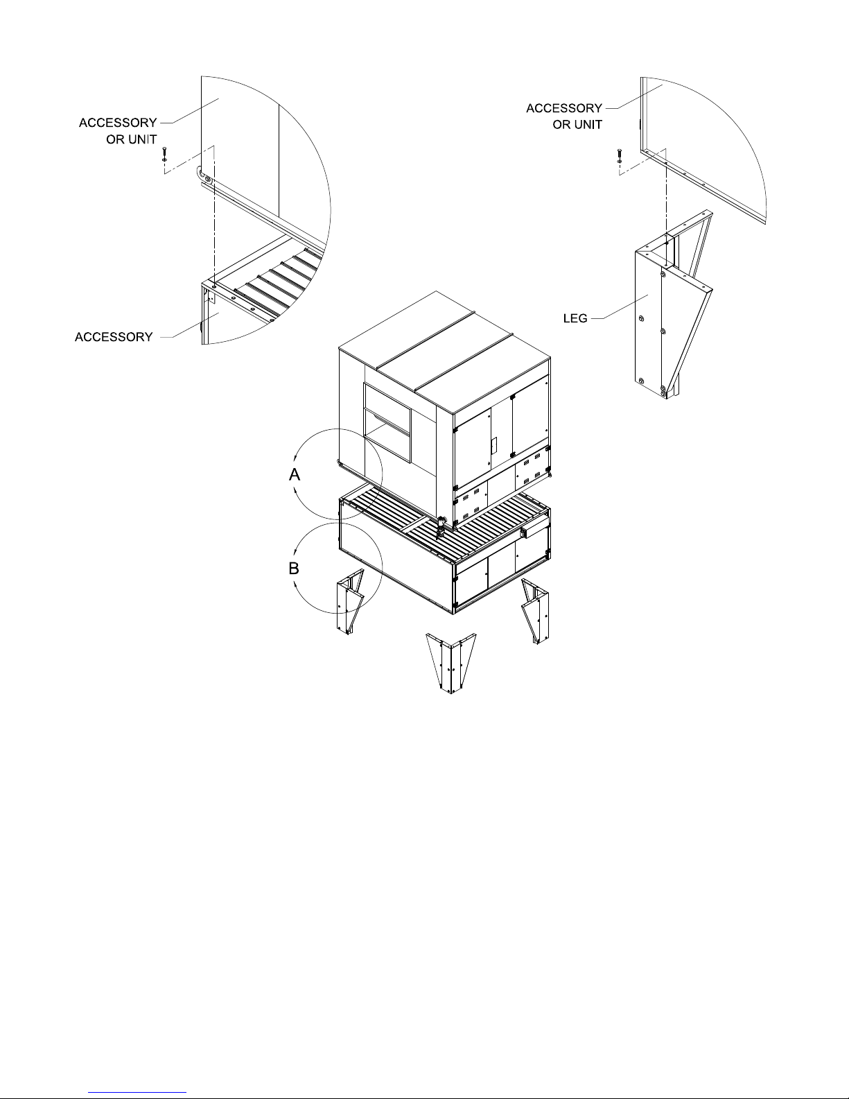
DETAIL A
DETAIL B
10. Apply a bead of latex based polyurethane caulk that
best matches the color of the exterior wall surface
of the facility and/or the color of the heater accessories at the joint between the top discharge duct and
outside wall surface. Make certain this is a continuous bead and that it runs the entire width of the duct.
Caulk all other exposed joints.
Cambridge Engineering, Inc. 20 M-Series Technical Manual
11. Install the discharge plenum by screwing the plenum
to the discharge duct. Install hanging rods from ceiling supports to the plenum’s support brackets.

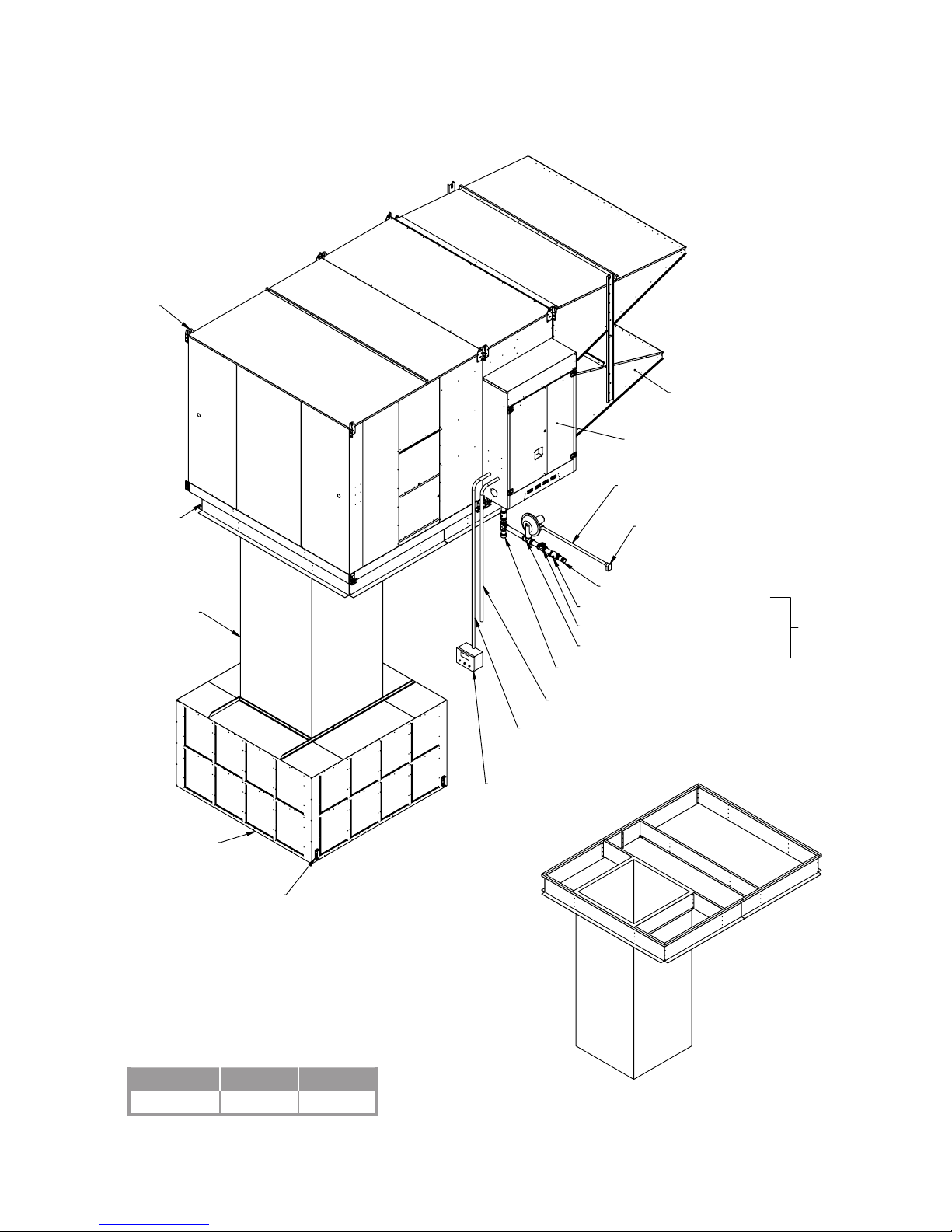
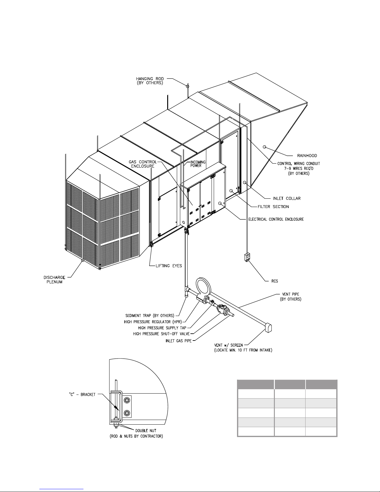
TYPICAL INSTALLATION
HIGH PRESSURE REGULATOR (HPR)
VERTICAL MOUNT - OUTDOOR CONFIGURATION
HORIZONTAL BLAST
M118 - M136
LIFTING
BRACKETS
EXTERNAL WALL
WALL FLASHING
(BY OTHERS)
CONTROL WIRING CONDUIT
7-9 WIRES REQ'D
(BY OTHERS)
Wall Opening
Model W H
M118
M120
M125
M130
M136
RCS
INCOMING
POWER
25.5" 25.5"
29.5" 29.5"
35" 35"
41" 41"
47" 47"
SEDIMENT TRAP
(BY OTHERS)
VENT PIPE
(BY OTHERS)
INLET GAS PIPE
HIGH PRESSURE SHUT-OFF VALVE
HIGH PRESSURE SUPPLY TAP
VENT w/ SCREEN
(LOCATE MIN.
10 FT FROM INTAKE)
HPR
(OPTION)
M-Series Technical Manual 21 Cambridge Engineering, Inc.

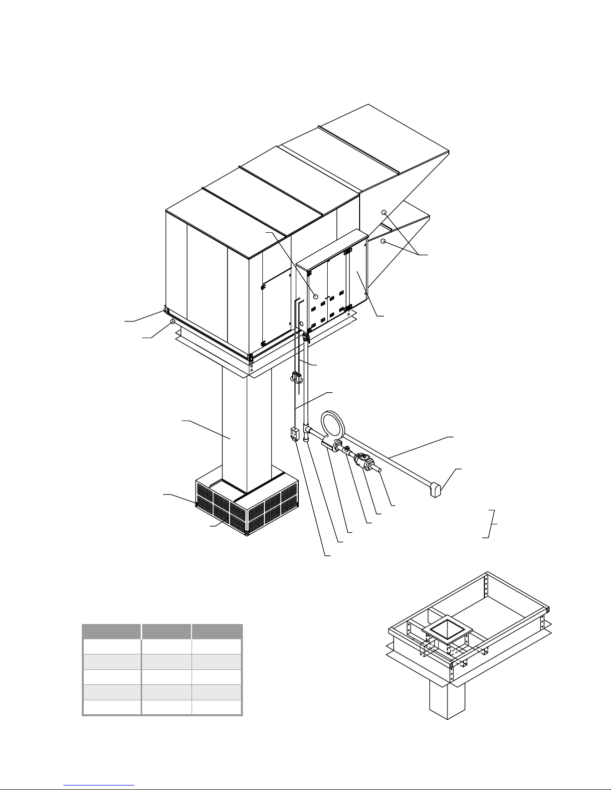
TYPICAL INSTALLATION
(OPTION)
VERTICAL MOUNT - OUTDOOR CONFIGURATION
UP BLAST
M118 - M136
DISCHARGE DUCT
DISCHARGE ELBOW
W/ TURNING VANES
DISCHARGE DUCT
Model W H
M118
M120
M125
M130
M136
Wall Opening
25.5" 25.5"
29.5" 29.5"
35" 35"
41" 41"
47" 47"
WALL FLASHING
(BY OTHERS)
EXTERNAL WALL
RCS
CONTROL WIRING CONDUIT
7-9 WIRES REQ'D
(BY OTHERS)
INSULATION
DUCT OPENING COLLAR
TEK SCREW
OUTER PERIMETER
INCOMING
POWER
SEDIMENT TRAP
(BY OTHERS)
DISCHARGE DUCT
UNIT ROOF
LIFTING BRACKETS
VENT PIPE
(BY OTHERS)
VENT w/ SCREEN
(LOCATE MIN. 10 FT
FROM INTAKE)
INLET GAS PIPE
HIGH PRESSURE SHUT-OFF VALVE
HIGH PRESSURE SUPPLY TAP
HIGH PRESSURE REGULATOR (HPR)
HPR
Cambridge Engineering, Inc. 22 M-Series Technical Manual

INSTALLATION INSTRUCTIONS
VERTICAL MOUNT - INDOOR CONFIGURATION
IMPORTANT
Before proceeding with installation, verify the feasibility of the location selected with respect to accessibility
to the equipment for service and maintenance functions.
IMPORTANT
To prevent contaminated air from being drawn into the
heater, install the heater’s inlet at least 10 feet from
any building exhaust, process exhaust, sewer stacks,
or other sources that would allow contaminants to be
drawn into the heater. Consult local codes for applicable building code provisions for ventilation air.
1. Prepare the wall for installation. (See page 25 for
opening dimensions for your specific heater.)
4. Attach each Mounting Leg to the inlet elbow using
the 1/2"-13 x 1-1/2" bolts. The bolts install downward through a clearance hole in the accessory into
a threaded insert in the Mounting Leg. Install all
four legs on the accessory, and then attach the inlet
collar to the inlet elbow using the 5/16"-18 x 1/2"
bolts. Position this assembly with the inlet collar
situated through the wall. Level the assembly by
placing shims under the appropriate legs.
5. Position the next inlet accessory, if specified, on
the inlet elbow, and then secure them to each other
using the 1/2"-13 x 1-1/2" bolts. The bolts install
downward through a clearance hole in the upper
accessory into a threaded insert in the inlet elbow.
IMPORTANT
Accurate measurements are critical and will affect the
installation process.
2. Install heater support rods per the structural engineer’s recommendations.
3. Use a crane or comparable lifting device to raise and
position the equipment. Block the heater where necessary. Use a spreader bar to prevent damage and
connect slings to the lifting eyes.
The Vertical Mount heaters may be shipped in
sections due to shipping constraints. Review the
Accessory Identification drawings (see page 4) to
identify the locations of these sections.
IMPORTANT
Cambridge Engineering recommends mounting the
heater’s rain hood a minimum of 60" off the ground or
other surfaces in areas where snow accumulation could
impact operation.
6. Position the heater on the last inlet accessory.
Secure the heater using the 1/2"-13 x 1-1/2" bolts.
The bolts install downward through a clearance hole
in the heater into a threaded insert in the inlet accessory.
7. Attach the rain hoods to the inlet collar using the
5/16"-18 x 1/2" bolts.
8. Install fiberglass insulation in the gaps around the
wall opening and inlet collar. Apply enough insulation material to accommodate the full thickness of
the wall.
9. Install finish trim pieces (by others) to the top, sides
and bottom of the inlet collar on both the inside and
outside wall surfaces.
M-Series Technical Manual 23 Cambridge Engineering, Inc.
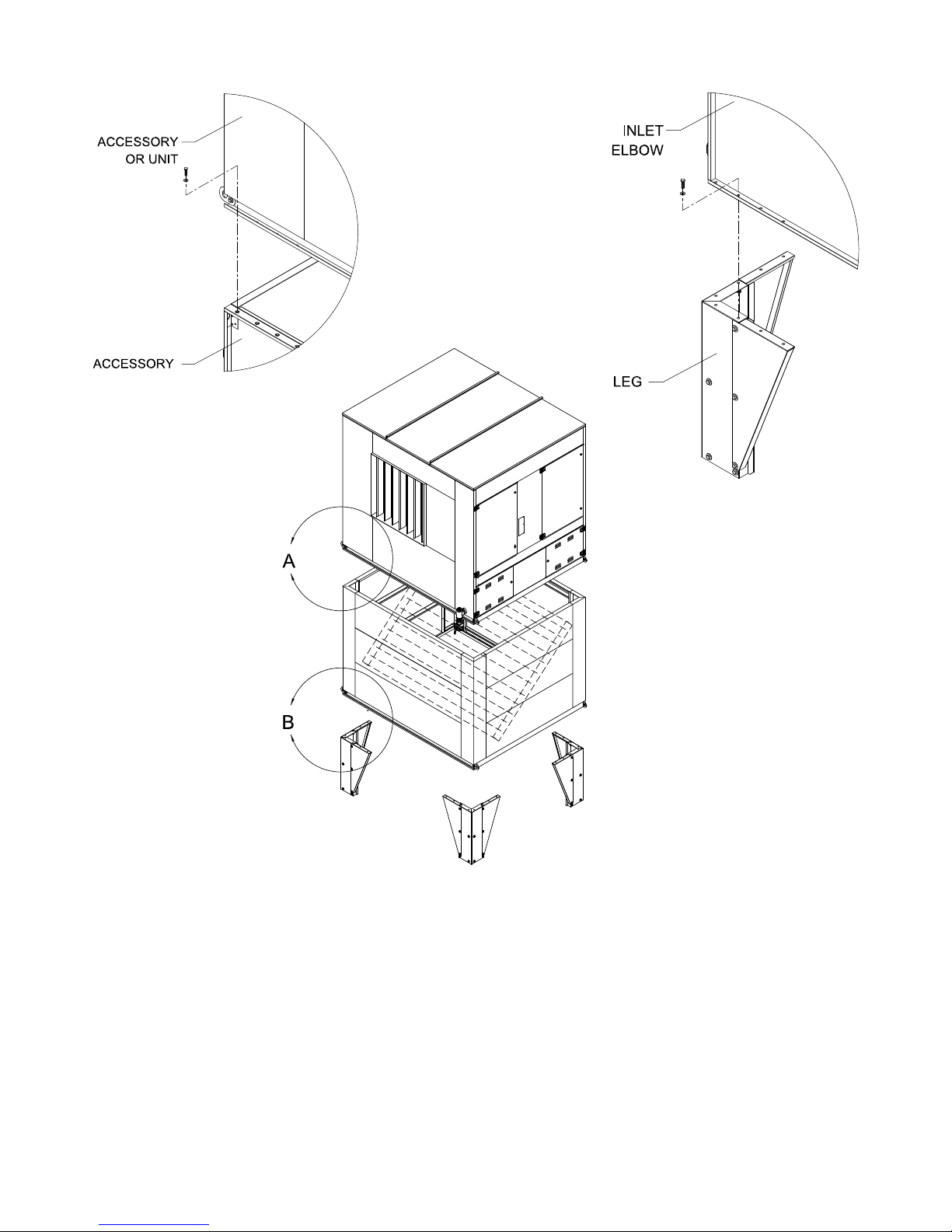
DETAIL A
DETAIL B
10. Apply a bead of latex based polyurethane caulk that
best matches the color of the exterior wall surface of
the facility and/or the color of the heater accessories
at the joint between the top inlet collar and outside
wall surface. Make certain this is a continuous bead
and that it runs the entire width of the collar. Caulk
all other exposed joints.
Cambridge Engineering, Inc. 24 M-Series Technical Manual
11. Install the discharge plenum by screwing the plenum
to the heater. Install hanging rods from the ceiling
supports to the plenum’s support brackets.
 Loading...