

CAMBRIDGE DL-CSW-10AT-LFT Installation, Setup And Operation

2
TABLE OF CONTENTS
Specifications-------------------------------------------------------3
Owner’s Information-----------------------------------------------4
Parts Description----------------------------------------------------5
Unpacking your Scale----------------------------------------------5
Equipment Needed for Installation-------------------------------6
Installation: Scale Section-----------------------------------------6-7
Installation: CSW-10AT-LFT Meter & Bracket---------------------8-9
Meter Connections-------------------------------------------------10
Operation------------------------------------------------------------11
1.0 Scale Procedure------------------------------------------------12
1.1 Software Navigation Flowchart-------------------------12-13
1.2 Navigation Keys-------------------------------------------13
1.3 Scale Menu Definitions-----------------------------------14-15
1.4 Numeric Entries---------------------------------------------------16
1.5 Set Up Parameters------------------------------------------------16
2.0 Calibration Procedures------------------------------------------------17
2.1 Calibration Menu Definitions-----------------------------------17
2.2 Calibration---------------------------------------------------------18
2.3 Linearity Calibration---------------------------------------------18
3.0 Communications Setup------------------------------------------------19
3.1 Communications Menu Definitions----------------------------19-20
4.0 Testing Procedure------------------------------------------------------21
4.1 Testing Menu Definitions----------------------------------------21
5.0 Warranty----------------------------------------------------------------22
6.0 Assistance--------------------------------------------------------------22

3
SPECIFICATIONS
Model CSW-10AT-LFT Electronic Lift Truck Scale:
Accuracy: .01% of applied load.
Operating Temperature: 14 to 140 deg. F (-10 to 60 deg. C)
Overload: 500% of Rated Capacity.
Capacity: 5,000 Pounds.
Meter: CSW-10AT-LFT with:
- .56 inch led display
- RS-232 Port for peripheral Device
- Mounting Hardware
- Operator Friendly
Warranty: Twelve (12) month Warranty against defect in
workmanship and/or materials
4
topNew Text
OWNERS INFORMATION
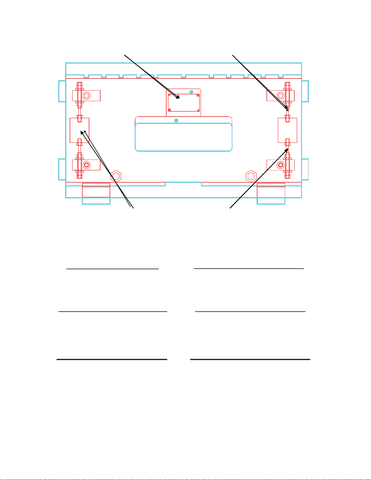
Junction Box Top Flexure Rod
Load Cell Bottom Flexure Rod
Meter Serial Number: Scale Section Serial Number:
#1 Load Cell Serial Number: #2 Load Cell Serial Number:
Scale Capacity and Graduation
Capacity: X Graduation: lbs

5
PARTS DESCRIPTION
SCALE SECTION
The scale section attaches to the lift truck carriage and you will install your
existing forks to the front of it. The scale section detects the weight of the load.
The weight of the load is then sent to the CSW-10AT-LFT Meter through the signal
cable.
CSW-10AT-LFT METER
The CSW-10AT-LFT Meter converts the weight from the scale section into
an accurate digital weight and displays it. Additionally, the CSW-10AT-LFT
sends data/information to peripheral devices. Mounting hardware is also
provided for the CSW-10AT-LFT so that it may be mounted to your fork truck
in either the dash mount or overhead mount.
UNPACKING YOUR SCALE
Your CAMBRIDGE Lift Truck Scale is shipped on a pallet. A Lift Truck Scale
system includes the following components:
1) One Scale Section to attach to the forklift carriage with bottom cleats.
2) One Signal Cable (coil).
3) One Power Cable.
4) One Electronic Meter (CSW-10AT-LFT) with mounting hardware.
5) One Cable Protection Guard - attached to the scale section.
6) Ten 5 1/2 inch wire ties.
7) Ten 21 inch wire ties.
Upon receipt of your scale system, please inspect to make sure the above parts
are present in your shipment.

6
EQUIPMENT NEEDED FOR INSTALLATION
Prior to installing your lift truck scale, gather all equipment (listed below)
needed to complete the installation;
- 1/2-inch hex allen wrench for removing and reinstalling the bottom cleats
- 1-1/2 inch open end wrench for adjusting the carriage adjustment bolts and
tightening the nuts of the carriage adjustment bolts
- Cutting pliers for cutting the wire ties
- Adjustable wrench (10-inch) for installing the cable protection guard
- 5/16-inch hex allen wrench for removing and installing fork stops
- 4-inch grinder
INSTALLATION: SCALE SECTION
NOTE: The Scale Section is shipped with the carriage adjustment bolts backed
out. You must adjust the carriage adjustment bolts. Improper installation
of the scale section causes most weighing problems. When installing the
the scale section keep the following in mind.
1) Scale section must touch the carriage at four points.
2) Scale section must be as parallel as possible to the carriage.
3) Scale section must not rock, swing, or slide in any direction.
INSTALLATION:
1) Remove forks from your existing truck. Remove backrest if required
2) Make sure the carriage face is not too rough; if it is, use the grinder
over any uneven areas.
3) Remove the bottom cleats from the scale section using the 1/2 inch
hex allen wrench.
4) Remove the cable protection guard and bolt. Install the lifting eye provided.
This allows you to lift the complete scale for installation.

7
INSTALLATION: SCALE SECTION-Continued
5) Attach the scale section to the existing carriage. The top cleats of the scale
will hold it to the carriage.
6) Make sure the top cleats are seated solid on the top of the carriage. The
center stop pin should also be seated solid in the center notch of the carriage.
7) Raise the carriage and adjust the carriage adjustment bolts so that both
bolts touch the plate of the carriage and daylight can be seen between
the scale section and the carriage face. (lock down the bolts with locking
nuts, 1 1/2-inch). Make sure the bolts are tight.
8) Install the bottom cleats provided with your system. Make sure they are
tight. There must be daylight showing on the back and bottom of the
cleats. No part of the cleat should touch the bottom of the carriage. If
this happens, repeatability will be affected. Corrective action would be
to install washers between the cleat and scale back plate to provide a
clearance gap.
9) Remove the fork stops and attach the forks to the front of the scale.
10) Reinstall the fork stops.
11) Remove the lifting eye and reinstall the cable protection guard and bolt.
The scale section installation is now complete.
 Loading...