

Page 1
Page 2

TABLE OF CONTENTS
Meter Connections ---------------------------------------------------------- 3
1.0 Operation ---------------------------------------------------------------- 4
1.1 Key Functions -------------------------------------------------------- 4
1.2 Error Messages ------------------------------------------------------- 4
2.0 Scale Procedure --------------------------------------------------------- 5
2.1 Software Navigation Flowchart ------------------------------------ 5 & 6
2.2 Navigation Keys ------------------------------------------------------ 6
2.3 Scale Menu Definitions ---------------------------------------------- 7 & 8
2.4 Numeric Entries ------------------------------------------------------- 9
2.5 Set Up Parameters ----------------------------------------------------- 9
3.0 Calibration Procedures -------------------------------------------------- 10
3.1 Calibration Menu Definitions ---------------------------------------- 10
3.2 Calibration -------------------------------------------------------------- 11
3.3 Linearity Correction --------------------------------------------------- 11
4.0 Communications Setup -------------------------------------------------- 12
4.1 Communications Menu Definitions --------------------------------- 12 & 13
5.0 Testing Procedure -------------------------------------------------------- 14
5.1 Testing Menu Definitions --------------------------------------------- 14
6.0 Warranty ------------------------------------------------------------------- 15
7.0 Assistance ------------------------------------------------------------------ 16
CAMBRIDGE SCALE WORKS, INC. 2 MANUAL P/N 5999-1014-01
Page 3
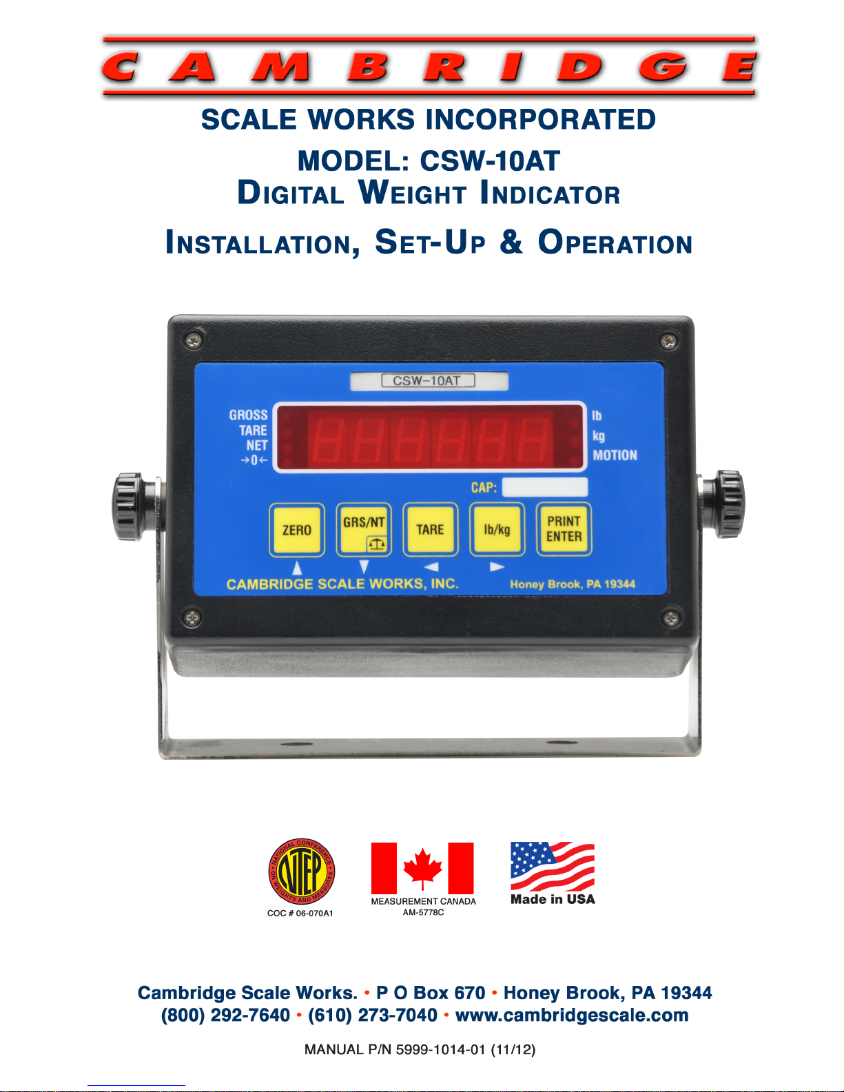
To connect power via AC wall adapter cable to the CSW-10AT
Meter. First make sure the On/Off Switch on the Rear of
Meter is in the OFF position. Connect the Transformer to y
your 110VAC outlet.
Next, connect the other
End of the cable to the
Rear of the Meter for
Power.
Meter Connections
Communications port Signal connection
PIN # DESCRIPTION PIN # DESCRIPTION
2 ----------- RXD 1 ----------- +EXC
3 ----------- TXD 2 ----------- -SIG
4 ----------- +5V 5 ----------- SHIELD LOAD CELL
6 ----------- -EXC
7 ----------- +SIG
5 ------------ SGND
CAMBRIDGE SCALE WORKS, INC. 3 MANUAL P/N 5999-1014-01
Page 4

1.1 Key Functions:
ZERO Brings the scale to a zero balance reading.
If the Zero key is pressed and held for 5 seconds the
Calibration zero value will be displayed.
GRS/NET Toggles the display between Gross weight and Net weight.
This key is also used to enter setup mode. Begin by pressing
and holding this key until the Parameter (Pxxx) Event counter
is displayed, then release. Immediately after COdE is displayed
enter in sequence (within 5 sec) Tare, lb/kg, GRS/NET, and
Print/Enter the display will indicate
ScAlE
.
-P xxx and C xxx are event counters that will increment
each time one or more changes are made to the Scale
or Calibration Parameters.
TARE Enters the Gross weight value into the Tare display and
switches to the Net display mode.
If the Tare key is pressed and held for 5 seconds the
current Tare value will be displayed.
lb/kg Toggles the display between pounds and kilograms.
PRINT Outputs the displayed weight data to the RS-232 Port.
Note: All keys are disabled when the scale is in motion or overload.
1.2 Error Messages
ScnEg When the weight is more than 10 divisions negative from
the zero calibration point.
oLD The Scale is in an overload condition.
bAt LO
Will flash when the Battery voltage falls to 10.8VDC and will
be displayed continuously when the voltage falls to 10.2VDC.
Err d
More than 5,000 scale divisions have been selected in
S1 Ntep or S1 Angle mode.
More than 20,000 scale divisions have been selected in
S1 NO mode.
1.0 OPERATION
CAMBRIDGE SCALE WORKS, INC. 4 MANUAL P/N 5999-1014-01
Page 5

2.1 SOFTWARE NAVIGATION FLOWCHART
SCALE
CALIBRATION
RS-232
TEST
END
S1
Ntep
Ntep,no,angle
(Ntep)
S2
CAPACITY
1-999,999
(5000)
S3
COUNT BY
1,2,5,/DEC
(1)
S4
OVERLOAD
105% OF CAP
OR ENTERED
S5
ZERO LIMIT
S6
FILTER
S7
MOTION BAND
S8
MOTION DELAY
100%,1.9%
(100%)
0 Fastest to 7
slowest (3)
1 TO 99
Divisions (2)
0 to 99
UPDATES (4)
C1
Zero & Clear All
Points
C2
ZERO
SHOW RAW
COUNTS THEN 0
SHOW RAW
COUNTS THEN 0
SHOW ACTUAL
WEIGHT
C3
SPAN POINT
C4
SPAN POINT
C5
SPAN POINT
C6
SPAN POINT
C7
SPAN POINT
END
R1
BAUD RATE
R2
Output Format
R3
Output Type
R4
Receiver mode
1200,8,N,1-
19200,8,N,1?
WT ONLY,
G, N (GTN)
(Key) Polled,
Continuous
(Disabled)
Rec.,Remote
END
T1
VERSION
T2
DISPLAY
LIGHT
SEGMENTS
SOFTWARE
VERSION
T3
BUTTONS
b1-b4,
b5 EXITS
T4
A TO D
A/D RAW
COUNTS
T5
SERIAL
Jumper Rx,Tx
Loop Back
T6
Cal Factors ?
T7
DEFAULT
YES, NO
END
2.0 SCALE PROCEDURE
CAMBRIDGE SCALE WORKS, INC. 5 MANUAL P/N 5999-1014-01
Page 6

2.2 NAVIGATION KEYS
During setup you will be required to make numeric entries. (Ex: Capacity, Zero Band, etc...)
The following table outlines the keys used to perform these entries along with their function.
ZERO-------KEY IS USED TO NAVIGATE UP.
GRS/NET---KEY IS USED TO NAVIGATE DOWN.
TARE--------KEY IS USED TO NAVIGATE LEFT.
lb/kg---------KEY IS USED TO NAVIGATE RIGHT.
PRINT-------KEY IS USED TO ENTER DATA AND RETURNS.
2.1 SOFTWARE NAVIGATION FLOWCHART (CONTINUED)
S9
Motion Display
Normal, Blank,
Dashes (Normal)
S10
ZERO BAND
1-99
DIVISIONS(2)
S11
ZERO DELAY
0-99
UPDATES(2)
1-99
DIVISIONS(1)
1-99
1/4secinc.(0)
lb ,kg, lb/kg
(lb/kg)
S12
Zero Tracking
S13
Tracking DELAY
S14
Display lb/kg
S15
SCALE ID
S16
BRIGHTNESS
S17
SLEEP MODE
END
1-99 (1)
ID IN TX
1-15
(15) BRIGHTEST
0 to 30 min
blanks dsp (0)
CAMBRIDGE SCALE WORKS, INC. 6 MANUAL P/N 5999-1014-01
S18
ANGLE LIMIT
0 - 9 Deg.
(6)
Page 7

2.3 Scale Menu Definitions:
S1 NTEP
(Ntep): Maximum divisions limited to 5,000.
Scale negative message is displayed if the gross weight
goes more than 10 divisions below zero. If a capacity and
count by of more than 5,000 divisions is selected ERR d
will be displayed and you will be returned to S2 to
select a new capacity or count by.
Angle: Enables angle correction for Legal For Trade
lift truck scales.
No: 20,000 maximum division limits and no scale negative tests.
S2 Capacity
1 to 950,000 pounds (5,000).
S3 Count By .001, .01, .1, (1), 10, 100,
.002, .02, .2, 2, 20, 200
.005, .05, .5, 5, 50, 500
S4 Over load (105%) of scale capacity or user entered value.
S5 Zero Limit (100%) or 1.9% of scale capacity.
S6 Filter 0 - 7 (3) 0 is the fastest response or least filtering and 7 is
the slowest response or most filtering
S7 Motion Band 1 to 99 divisions (2) the weight display must be
stable within the selected number of division
for the motion indicator to be turned off.
S8 Motion Delay 0 to 99 updates (4) the weight display must be
within the motion band for the selected number
of updates for the motion indicator to be turned off.
S9 Motion (Normal): When the scale is in motion the motion LED will
Display light.
Blank: When the scale is in motion the display will be
blanked out.
Dashes: When the scale is in motion the display will show
all Dashes.
S10 Zero Band 1 to 99 divisions (2) the weight display must return
to Zero within the selected number of divisions to
to be considered Zero.
CAMBRIDGE SCALE WORKS, INC. 7 MANUAL P/N 5999-1014-01
Page 8

2.3 Scale Menu Definitions Continued:
S11 Zero Delay 0 to 99 updates (4) the weight display must be within
the zero band for the selected number of updates to
be considered Zero.
S12 Zero Tracking 1 to 99 divisions (2) the number of graduations
allowed to be Automatically Zeroed off.
S13 Tracking Delay 0 to 99 updates (0) the amount of time the display
must be within the allowed graduations before it will
be automatically Zeroed.
(0) disables zero tracking.
S14 Lb/Kg (Lb/KG): Allows the indicator to be switched between pounds
and kilograms by pressing the lb/kg key.
LB: This sets the display to Pounds only.
Kg: This sets the display to Kilograms only.
S15 Scale ID (1) to 99 scale ID used in RF link output.
S16 Brightness 0 to (15) adjusts the LED display intensity 15 is
the brightest.
S17 Sleep Mode (0) to 30 minutes. The display will turn off after the
the set amount of time elapses with no scale activity.
S18
Angle Limit (6) Adjusts maximum angle.
END Exits back to the main Menu.
( ) indicates Factory Set defaults.
CAMBRIDGE SCALE WORKS, INC.
8 MANUAL P/N 5999-1014-01
Page 9

2.4 Numeric Entries
When entering a numeric value, First press and release the lb/kg key to move
right into the menu where the numeric value will be entered. Then press and release
the Zero key, the first digit in the value will flash. Press and release the ZERO and
GRS/NET keys to increase or decrease the digits value. Press and release the Tare
key to move to the next digit. Repeat the steps above to adjust the digits value.
Repeat all steps until the numeric value is correct, then press and release the
PRINT
key to enter the data. The display will return to the menu.
2.5 Set Up Parameters
To begin press and hold the GRS/NET key until the Parameter (Pxxx) Event
counter is displayed, then release. Immediately after COdE is displayed, (within
5 seconds) enter in sequence Tare, lb/kg, GRS/NET, and Print/Enter, The display
will indicate ScAlE.
-P xxx and C xxx are event counters that will increment each time one or more
changes are made to the Scale or Calibration Parameters.
With the display indicating ScAlE, press the GRS/NET key to move down. This
allows the operator to change any of the scale Parameters S1 thru S17. For example,
press the GRS/NET key to move down until S2 is displayed, S2 is used to set the
Capacity of the Scale. Press the lb/kg key to move right in the S2 Parameter. The
current capacity will be displayed. Press the ZERO key; the first digit will flash.
Enter the capacity using the steps described in section 1.3. When the capacity is
correct, press the Print key to enter the value. The display will return to S2.
Entering the Count By. Press the GRS/NET to move down, S3 will be displayed.
Press the lb/kg key to move right into this parameter. The current "Count by" will be
displayed. Press the ZERO and GRS/NET keys to adjust the divisions. Press the Tare
and lb/kg keys to adjust the decimal point. Press the PRINT key when finished to enter
the data. The display will return to S3. Exit Set up Mode by pressing the Tare Key, End
will be displayed, then press Print/Enter.
CAMBRIDGE SCALE WORKS, INC. 9 MANUAL P/N 5999-1014-01
Page 10

3
.1
Calibration Menu Definitions:
C1 Zero All Raw counts, (pitch and roll if in angle mode) will be displayed.
When ZERO is pressed an analog zero is done and all
calibration span points will be cleared.
If in angle mode the pitch and roll offsets will also be zeroed.
C2 Zero Zeroed Raw counts, (pitch and roll if in angle mode will be
displayed). When ZERO is pressed an analog zero is done
and all calibration span points will NOT be cleared.
If in angle mode the pitch and roll offsets will also be zeroed.
C3 Span Point The last Calibration weight will be displayed then the
actual weight on the scale will be displayed.
If you do not wish to change the span point, press the
TARE key to exit without making any changes.
If the displayed weight does not match the known test
weight, press the ZERO key to enter the correct weight.
Use the steps described in section 2.4 for numeric entry.
When the weight is correct press the Print key to enter
the new value.
C4 to C7 Span points C4 to C7 are for linearity correction, they can be used in
order and in any quantity or not at all if no correction is
necessary.
You may also return to C4 to C7 later and add a new
correction point without affecting any original calibration
points.
The last calibration weight will be displayed then the actual
weight on the scale will be displayed. If no calibration weight
has been entered at this span point
"notset"
will be displayed
then the actual weight on the scale is displayed. If the
displayed weight does not match the known test weight,
follow the steps described for C3 Span point on adjusting the
weight and entering the value.
END Exits back to the main Menu.
3.0 CALIBRATION PROCEDURES
CAMBRIDGE SCALE WORKS, INC. 10 MANUAL P/N 5999-1014-01
Page 11

3.2 Calibration
Press and hold the
GRS/NET
key, as described previously in section 2.5. ScAlE
will be displayed. Press the lb/kg key to move right, CALib will be displayed. Press
the GRS/NET key to move down, C1
will be displayed. Press the lb/kg key to move
right, the Raw counts will be displayed. With no weight on the scale and the scale
level, press the ZERO button, “0” will be displayed. Press the Print/Enter key to enter
the data. “0” is now entered and the display returns to C1.
Note: With the scale completely level use C1 or C2 to zero the angles. There is no need to use both C1 and C2.
need to use both C1 and C2.
Press GRS/NET key to move down, C3 will be displayed. Press the lb/kg key to
move to the right, the last calibrated weight will flash then the current weight on the
scale is displayed. Place a known test weight on the scale with the forks level. Press
the ZERO key, the first digit of the weight will flash. Use the ZERO and GRS/NET
keys to increase or decrease the digits value. Press the TARE key to move left, the
next digit will flash. Repeat the steps until the correct weight is entered. Press the
PRINT key to record the data. The display will return to C3.
Press the GRS/NET key until End is displayed, then Press PRINT. Calibration
is now complete.
3.3 Linearity Correction
If Linearity Correction is needed, Press the GRS/NET key (from the calibration
menu) to move down to C4. Press the lb/kg key to move right, the last calibrated
weight will flash or “notset” will flash if this point has not been previously set. Next
the current weight on the scale will be displayed. Place a known test weight on the
scale with the forks level. Press the ZERO Key for the first digit of the displayed
weight to flash. Enter the weight as described in section 1.4, then press the PRINT
key to record the data. Continue these steps for C5, C6 and C7.
Linearity Correction points (C4-C7) can be used in any order and in any quantity
or not at all if no correction is necessary. After calibration is complete you may also
return to these correction points and make changes to its value without affecting any
of the original calibration points.
CAMBRIDGE SCALE WORKS, INC. 11 MANUAL P/N 5999-1014-01
Page 12

4.1 Communications Menu Definitions:
R1 Baud Rate 1200 to 115200 baud (9600), 8, n, 1
R2 Output 0 - (Gross, Tare, Net)- "CR, LF, CR, LF [32 bytes of 2Eh],
Format CR, LF, CR, LF, Gross (lb or kg), :, six ASCII characters
[indicated weight], CR, LF, Tare (lb or kg), sp, :, six
ASCII characters (indicated weight), CR, LF, CR, LF, CR
LF, CR, LF" [100 bytes total output].
1 - (Weight only)- "Six ASCII Characters [indicated weight],
CR, LF" [8 bytes total output].
2 - (Net only)- "NT, Sp, Six ASCII Characters [indicated
weight], Sp, lb or kg, CR, LF" [14 bytes total output].
3 - (Gross only)- "GR, Sp, Six ASCII Charactes [indicated
weight], Sp, lb or kg, CR, LF" [14 bytes total output].
R3 Output Type 0 - Output on command, standard print.
Output as selected by R2 Output Format.
If "Q" is received on the serial port the scale will output
the same as if the PRINT key were Pressed.
The same holds true for Z = Zero
U = lb/kg
D = GRS/NET
T = TARE
1 - Slave Display Output (numeric only) continuous
Stx, Six ASCII Characters (indicated weight), CR, LF
[9 bytes total output].
2 - Slave Display Output (alphanumeric) continuous
Stx GR or NT or TR, six ASCII Characters (indicated
weight), lb or kg, CR, LF [15 bytes total output].
3 - RF Link Output.
4 - Used for QSI terminal.
4.0 COMMUNICATIONS SETUP
CAMBRIDGE SCALE WORKS, INC. 12 MANUAL P/N 5999-1014-01
Page 13

4.1 Communications Menu Definitions Continued:
R4 Receiver 0 - Disabled - normal scale mode.
1 - Standard Receiver.
Receives R3.3 RF link output string displaying data as
it appears on the scale. All keys are disabled except the
PRINT key.
2 - Remote control.
Receives R3.3 RF link output string displaying data as
it appears on the scale and allows full control of all scale
meter functions.
END Exits back to the main Menu.
( ) indicates Factory Default setting
CAMBRIDGE SCALE WORKS, INC. 13 MANUAL P/N 5999-1014-01
Page 14

5.1 Testing Menu Definitions:
T1 Version Displays Software Version.
T2 Display Lights all display segments and indicating LED s
T3 Buttons Press the Zero key, b1 will be displayed.
Press the GRS/NET key, b2 will be displayed.
Press the Tare key, b3 will be displayed.
Press the lb/kg key, b4 will be displayed.
Pressing the print key will exit back to the menu T3.
T4 A to D Displays Raw counts where a 1mV/V signal from the scale
will display 25,000 counts.
When in angle mode Down GRS/NET will cycle Pitch, Roll
and Raw counts.
T5 Serial Serial communications can be verified by connecting pins
2 and 3 on the serial port. A single character will be echoed
and pass or fail will be displayed.
T6 Setup data Setup data will be sent out on the printer port.
T7 Default Resets the meter back to factory defaults clearing all
calibration and setup data. "r you sure?" will be displayed
then press the Tare key to exit without Defaulting, or press
the Print key to reset the meter to factory default.
END Exits back to the main Menu.
5.0 TESTING PROCEDURES
CAMBRIDGE SCALE WORKS, INC. 14 MANUAL P/N 5999-1014-01
Page 15

CAMBRIDGE warrants the CSW-10AT to be free of defects in workmanship
and/or materials for 12 months from the date of shipment. This warranty of
workmanship and/or materials is valid, if in the opinion of CAMBRIDGE, the
equipment has not been mechanically, environmentally, or electrically abused.
This warranty is limited, at the option of CAMBRIDGE, to repair, replace or an
appropriate credit adjustment not to exceed the original equipment sale price paid
to CAMBRIDGE. CAMBRIDGE
assumes no liability in connection with the sales
of its products beyond that stated above.
Warranty replacement parts and/or repair services are performed at the factory
in Cumberland, Maryland or by an authorized Service Group approved by
CAMBRIDGE.
Warranty does not include travel expense if a factory technician is requested
to perform repairs at a location other than the factory.
It's the user's responsibility to follow the proper set-up, calibration and operating
procedures of the CSW-10AT as described in this manual. If the operator has
difficulty using their
CSW-10AT properly, please contact CAMBRIDGE at
1-301-724-4082. Any of our technicians will be happy to work with the user via
telephone.
Thank You!
6.0 WARRANTY
CAMBRIDGE SCALE WORKS, INC. 15 MANUAL P/N 5999-1014-01
Page 16

If at any time you require assistance with your Model:
CSW-10AT Meter please contact us at:
CAMBRIDGE SCALE WORKS, INC.
115 West Mary Street
Cumberland, MD 21502
Phone: (301) 724-4082
Fax: (301) 724-4964
7.0 Assistance
CAMBRIDGE SCALE WORKS, INC. 16 MANUAL P/N 5999-1014-01
 Loading...