

Cambridge BLOW-THRU, DIRECT GAS-FIRED INDUSTRIAL BLOW-THRU User Manual
S-SERIES
®
DIRECT GAS-FIRED
INDUSTRIAL BLOW-THRU® SPACE HEATER
TECHNICAL MANUAL
mWARNING:
Improper installation, adjustment, alteration, service or maintenance can cause property
damage, injury or death. Read the installation, operating, and maintenance instructions
thoroughly before installing or servicing this equipment.
FOR YOUR SAFETY
The use and storage of gasoline or other flammable vapors and liquids in open containers
in the vicinity of this appliance is hazardous.
FOR YOUR SAFETY
If you smell gas:
1. Open windows.
2. Don’t touch electrical switches.
3. Extinguish any open flame.
4. Immediately call your gas supplier.
Made in the USA
ASHRAE
ASHRAE
90.1
COMPLIANT
COMPLIANT
®
S-TM8-0120

S-SERIES
BLOW-THRU
®
SPACE HE ATER
TECHNICAL MANUAL
LIMITED WARRANTY
Cambridge Air Solutions' Limited Warranty is included within the Terms and Conditions that are sent
with every Order Acknowledgement. For questions regarding Limited Warranty, contact Cambridge Air
Solutions' Customer Service Group at 1-800-473-4569.
Copyright © 2020
Cambridge Air Solutions
All Rights Reserved
Cambridge Air Solutions
760 Long Road Crossing Dr.
Chesterfield, MO. 63005
Phone: (636) 532-2233, (800) 899-1989
Fax: (636) 530-6133
www.cambridgeair.com

CONTENTS
Hazard Summary ................................................2
Typical System Overview ................................... 3
AccessoryIdentication .............................3
Heater Operation ........................................ 5
HeaterConguration .................................. 5
Installation Instructions ....................................... 6
Uncrating Instructions ................................ 6
Mounting Location .....................................6
Roof Top Mounting -
Curb / Stand / Rail......................................7
Roof Top / Thru Wall Mounting -
Stand / Rail ................................................. 8
Under Roof Mounting - Curb ....................8
Roof Top Mounting ....................................9
Thru Wall Mounting .................................11
Roof Top / Thru Wall Mounting ..............13
Under Roof Mounting .............................. 15
Vertical Indoor Mounting ......................... 17
Vertical Outdoor Mounting ...................... 19
Vertical S-Series
Structural Inlet Elbow .............................. 21
Vertical S-Series Structural
Non-Adjustable Elbow .............................25
Vertical S-Series Adjustable Stand ...........27
Vertical S-Series 3', 4', &5'
Duct Extensions .......................................30
Vertical S-Series Adjustable Elbow .........32
Vertical S-Series Structural
Filter Section ............................................ 34
S-Series 24", 38", & 50"
Wall Sleeves ............................................. 37
S-Series Downturn With Lugs ................ 39
S-Series Upturn ....................................... 41
Horizontal S-Series 4’
Mounting Stand .......................................43
Vertical Inlet Skirt ................................... 46
Rain Hood Inlet Skirt .............................. 47
Unit Inlet Skirt .........................................48
Gas Piping ................................................ 49
Electrical Wiring .....................................50
Remote Control Station and Temperature
Sensor Locations ...................................... 51
Thermistor Sensor .................................... 53
Start-Up Instructions ......................................... 54
Calibration Procedures ..................................... 60
Operating Instructions ....................................... 63
Operating Sequence .................................63
Electronic Thermostat .............................. 64
TSS Controller ........................................66
Bacnet Controller ..................................... 75
Maintenance Instructions .................................. 79
Troubleshooting Instructions ............................83
Troubleshooting Guide ............................83
Damper Motor Replacement
& Adjustment ........................................... 89
Reference ..........................................................91
Electrical Control Enclosure
Isometric Drawing ...................................91
Electrical Wiring Diagrams .....................92
Remote Control Station Electrical
Connection Diagram ...............................97
Building Automation System ................... 98
Gas Train Drawings .................................99
Individual Component
Descriptions ...........................................103
ANSI/ASHRAE/IESNA
Standard 90.1 .........................................109
Maintenance Log ............................................ 110
QR Code.......................................................... 113

HAZARD SUMMARY
Hazard Identification
Warnings and Cautions appear at appropriate sections throughout this manual. Read these carefully.
mWARNING: Indicates a potentially hazardous situation which could result in
death or serious injury.
CAUTION: Indicates a situation that may result in accidents with equipment or
mCAUTION: Indicates a potentially hazardous situation which may result in
minor or moderate injury. It may also be used to alert against
unsafe practices.
property damage only.
The following safety precautions apply to the
installation, operation, and maintenance of the
equipment described by this technical manual.
mWARNING:
Any unauthorized modification of this equipment
shall void the warranty.
mWARNING:
Only qualified personnel should attempt
installation, service, and repair of this equipment.
Use extreme caution and observe safety
regulations at all times.
mWARNING:
Recirculation of room air is not permitted.
Adequate building relief must be provided so as to not
over pressurize the building when the heating system
is operating at its rated capacity. It should be noted
that this can be accomplished by taking into account,
through standard engineering methods, the structure’s
designed infiltration rate, by providing properly sized
relief openings, or by interlocking a powered exhaust
system, or by a combination of these methods.
If the failure or malfunction of this heater creates
a hazard to other fuel burning equipment in the
building, (e.g. when the heater is providing the makeup air to a boiler room), the unit is to be interlocked to
open inlet air dampers or other such devices.
If the heater is installed such that an inlet duct is
utilized, the duct system must be purged with at least
four air changes prior to an ignition attempt.
Installation in Aircraft Hangars
Refer to the Standard for Aircraft Hangars,
ANSI/NFPA 409, for specific information on
the installation requirements for these heaters in
aircraft hangars.
Installation in Parking Garages
Refer to the Standard for Parking Structures,
ANSI/NFPA 88A, or the Standard for Repair
Garages, ANSI/NFPA 88B, for specific
information on the installation requirements for
these heaters in public
Installation in Car Wash Facilities
A non-recirculating, S-Series Space Heater used in
a Car Wash tunnel application may be designated
as a T-Series Heater on the nameplate.
This S-Series Technical Manual also applies to all
T-Series Heaters.
If in doubt regarding installation application, contact
Cambridge Customer Service Group at 1-800-4734569 during the hours of 8:00 a.m. to 5:00 p.m.
Central Time, Monday through Friday.
garages.
IMPORTANT
Cambridge Air Solutions 2 S-Series Technical Manual
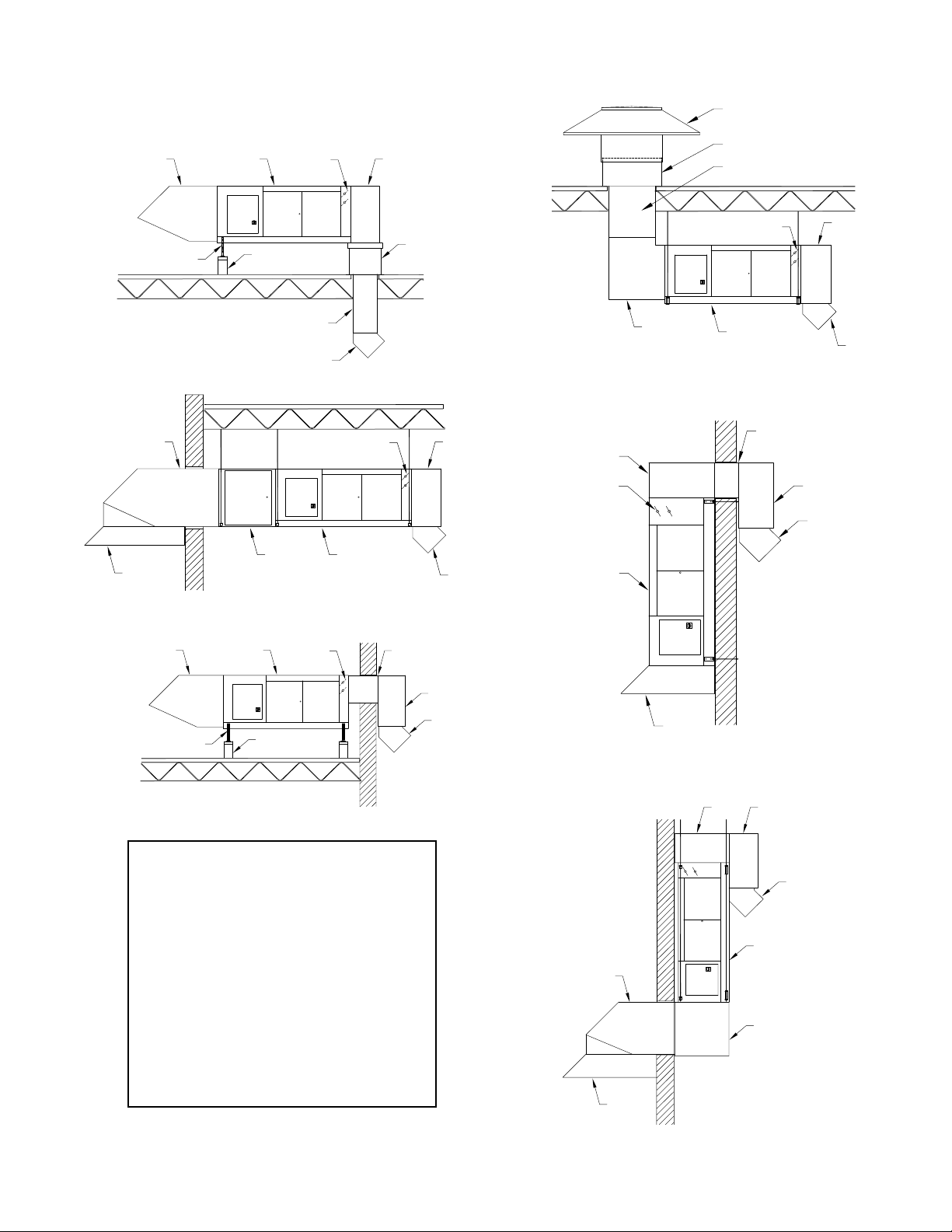
TYPICAL SYSTEM OVERVIEW
RH-RT
MDD
DT
UNIT
C
DE
DE
IP
ISU
ACCESSORY IDENTIFICATION
Under Roof Mounting
RH-TW
ISR
Roof Top Mounting
AMS
MR
DD
DE
Thru Wall Mounting
MC
ID
MDD
M
IE
UNIT
DT
Outdoor Vertical Mounting
MDD
UNITFS
DT
DT
MDD
UNIT
WALL SLEEVE
(BY OTHERS)
DT
DE
Roof Top / Thru Wall Mounting
RH-RT
AMS
Component Identification
AMS Adjustable Mounting Stand
DD Discharge Duct
DE Directional Elbows
DT Downturn
FS Filter Section
ID Inlet Duct
IE Inlet Elbow
IP Inlet Plenum
ISR Inlet Skirt-Rain Hood
ISU Inlet Skirt-Unit
MC Mounting Curb
MDD Motorized Discharge Damper
MR Mounting Rail
RH-RT Rain Hood-Roof Top
RH-TW Rain Hood-Thru Wall
UNIT
MDD
MR
WALL SLEEVE
(BY OTHERS)
DT
DE
Indoor Vertical Mounting
DT
DT
UNIT
RH-TW
IE
ISR
S-Series Technical Manual 3 Cambridge Air Solutions
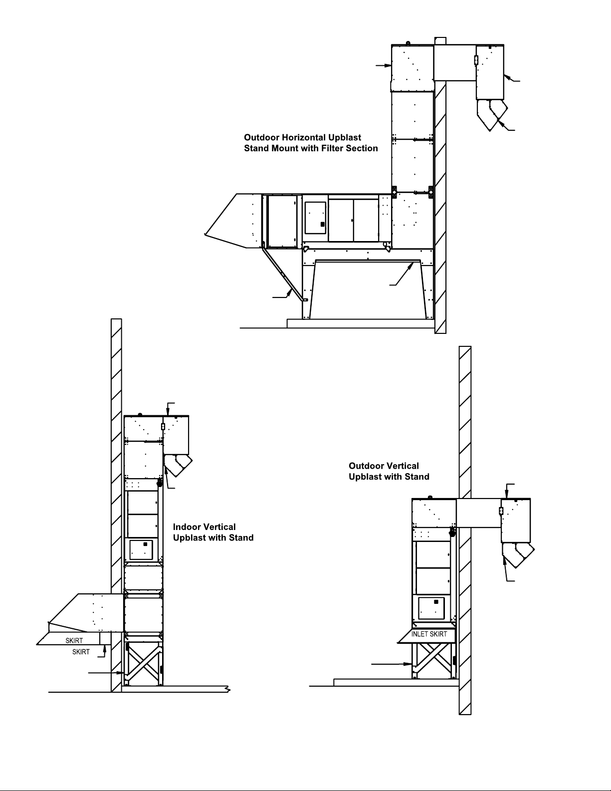
TYPICAL SYSTEM OVERVIEW
ACCESSORY IDENTIFICATION
ADJUSTABLE
ELBOW
WALL
SLEEVE
DOWNTURN
DUCT
EXTENSION
DIRECTIONAL
ELBOWS
DUCT
EXTENSION
DOWNTURN
DUCT
EXTENSION
DOWNTURN
DIRECTIONAL
ELBOWS
RAINHOOD
FILTER
SECTION
SUPPORT
FILTER
SECTION
UPTURN
HORIZONTAL
MOUNTING
STAND
DOWNTURN
WALL
SLEEVE
DIRECTIONAL
ELBOWS
RAINHOOD
EXTENSION
ADJUSTABLE
STAND
RAINHOOD
STRUCTURAL
FILTER
SECTION
STRUCTURAL
INLET
ELBOW
DOWNTURN
ADJUSTABLE
STAND
Cambridge Air Solutions 4 S-Series Technical Manual
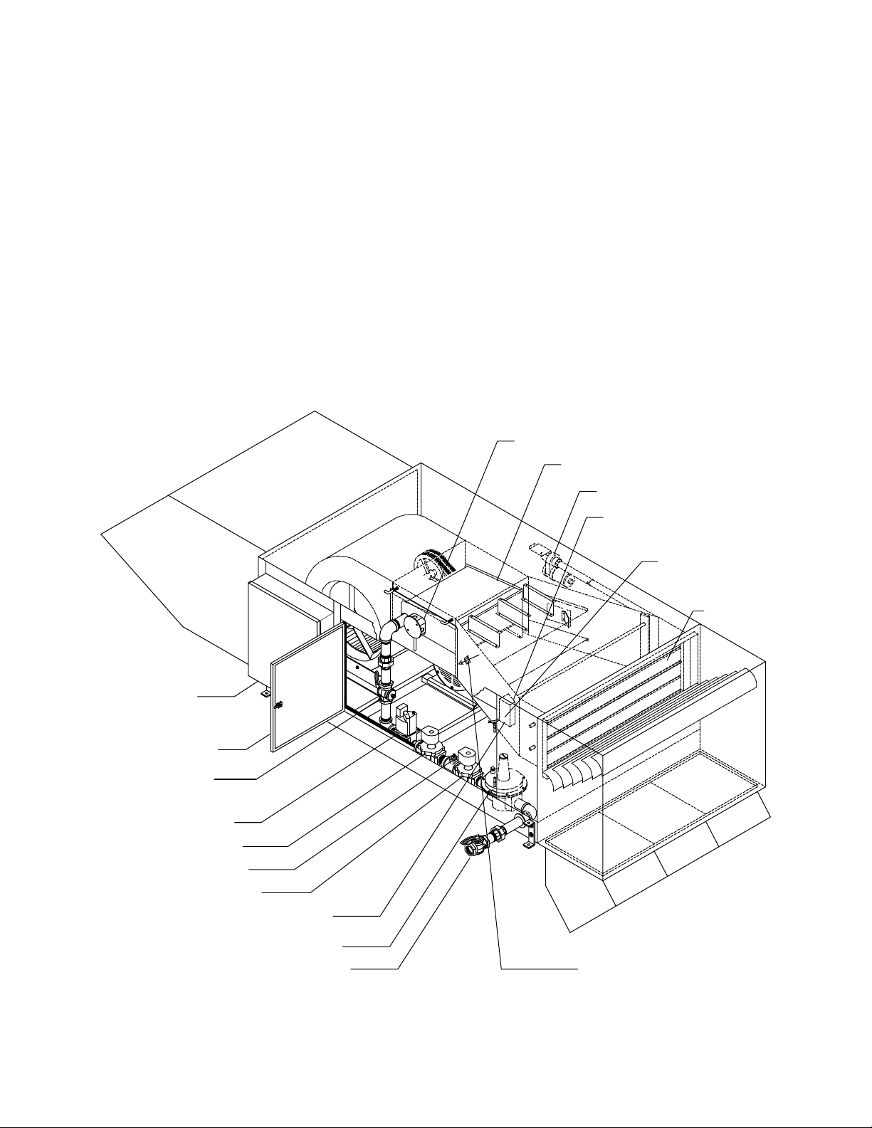
TYPICAL SYSTEM OVERVIEW
HEATER OPERATION
Cambridge S-Series Blow-Thru® heaters are utilized
to meet the space heating requirements of commercial
or industrial buildings. The control system is typically
designed to cycle the heaters on and off in response to
the rise and fall of the space temperature. The heater
will discharge air at the temperature selected (up to
HEATER CONFIGURATION
160ºF). The operating thermostat is typically located
near the perimeter of the building in a location which
is out of the direct path of the heated discharge air,
insulated from cold surfaces, and shielded from cold
drafts created by air infiltrating the building.
IGNITER & FLAMEROD
BURNER ASSEMBLY
DAMPER MOTOR
DISCHARGE TEMPERATURE SENSOR
ELECTRICAL
CONTROL ENCLOSURE
HINGED ACCESS DOOR
PORT FOR MEASURING
MANIFOLD PRESSURE
MODULATING GAS VALVE
SAFETY SHUT-OFF VALVE
LEAK TEST PORT
SHUT-OFF VALVE
DISCHARGE AIR TEMPERATURE
SAMPLING BOX
MANUAL SHUT-OFF VALVE BURNER VIEWPORT
HIGH LIMIT
DAMPER BLADES
REGULATOR
S-Series Technical Manual 5 Cambridge Air Solutions

INSTALLATION INSTRUCTIONS
UNCRATING INSTRUCTIONS
1. Verify that the number of items on the Bill of
Lading matches the number of items received.
2. Check for shipping damage. Take photographs of
any damage.
IMPORTANT
If damage is found, immediately file a claim with the
carrier before proceeding further.
3. Check the items received to make sure they agree
with the ordering information including verification
of data on the unit nameplate.
IMPORTANT
Do not discard any components or accessories.
MOUNTING LOCATION
Verify feasibility of the installation location selected
with respect to accessibility to the heater for service
and maintenance functions. Ensure the positioning
of the heater does not inhibit fork truck operation,
storage rack locations, or other operations within
the facility. Ensure the heater inlet and outlet are not
blocked or severely restricted in any way that would
affect the rated airflow through the heater or affect the
desired air distribution pattern of the heater.
It is the responsibility of the installer to communicate
any potential problems with the installation to
the person or persons responsible for providing
the installation instructions or drawings prior to
proceeding with the installation.
IMPORTANT
Where the mounting height of the heater is a
consideration, work platforms or service lifts should
be provided for accessibility to the equipment for
service and maintenance activities.
IMPORTANT
Field constructed intake accessories should be
designed to minimize the entry of snow and rain.
IMPORTANT
The minimum clearance from the face of the
electrical control enclosure to surrounding
grounded surfaces for service activities is 42”.
Adequate clearance of 42” for burner removal is
also required. Access for service functions is also
required on the side of the unit opposite the control
enclosure for a distance of 24”.
Cambridge Air Solutions 6 S-Series Technical Manual
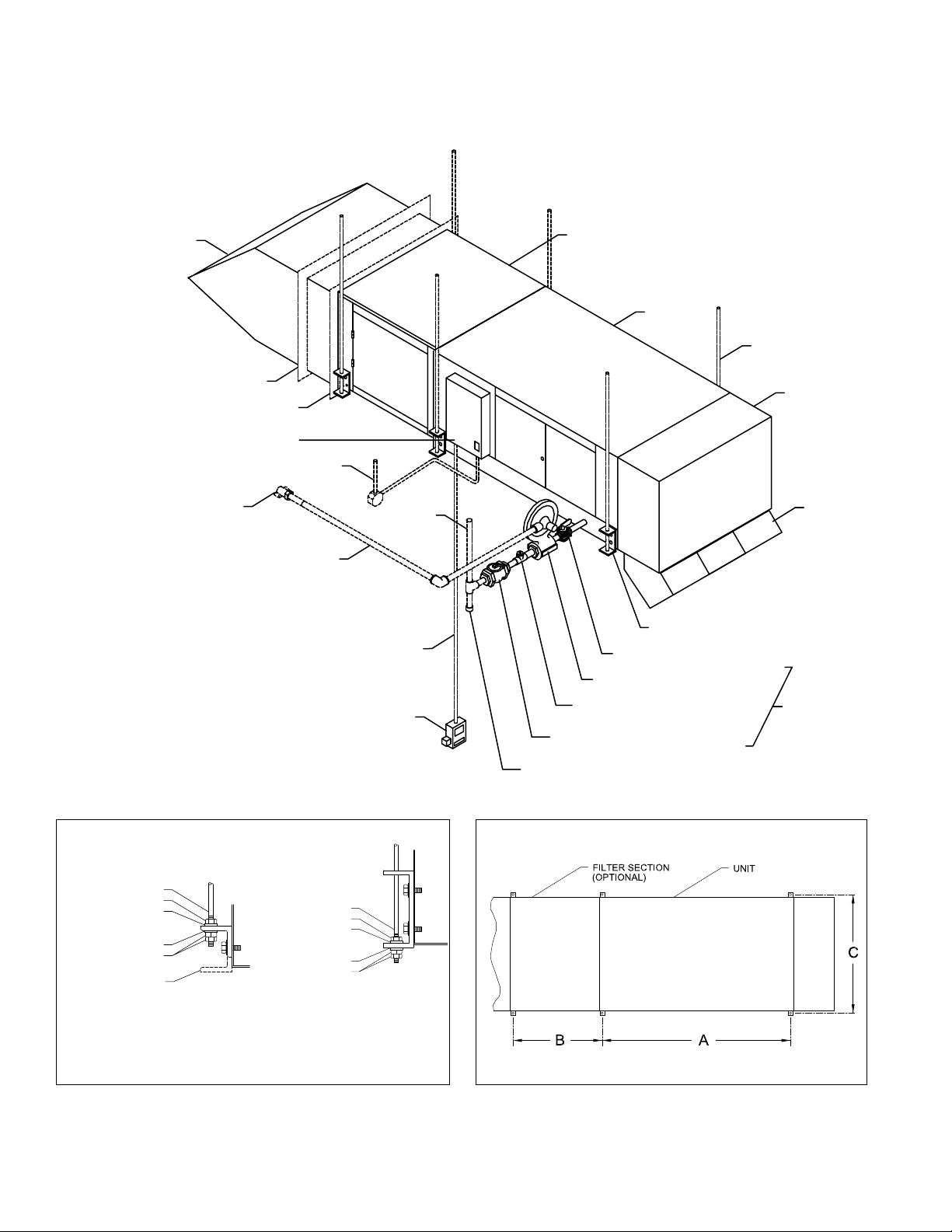
INSTALLATION INSTRUCTIONS
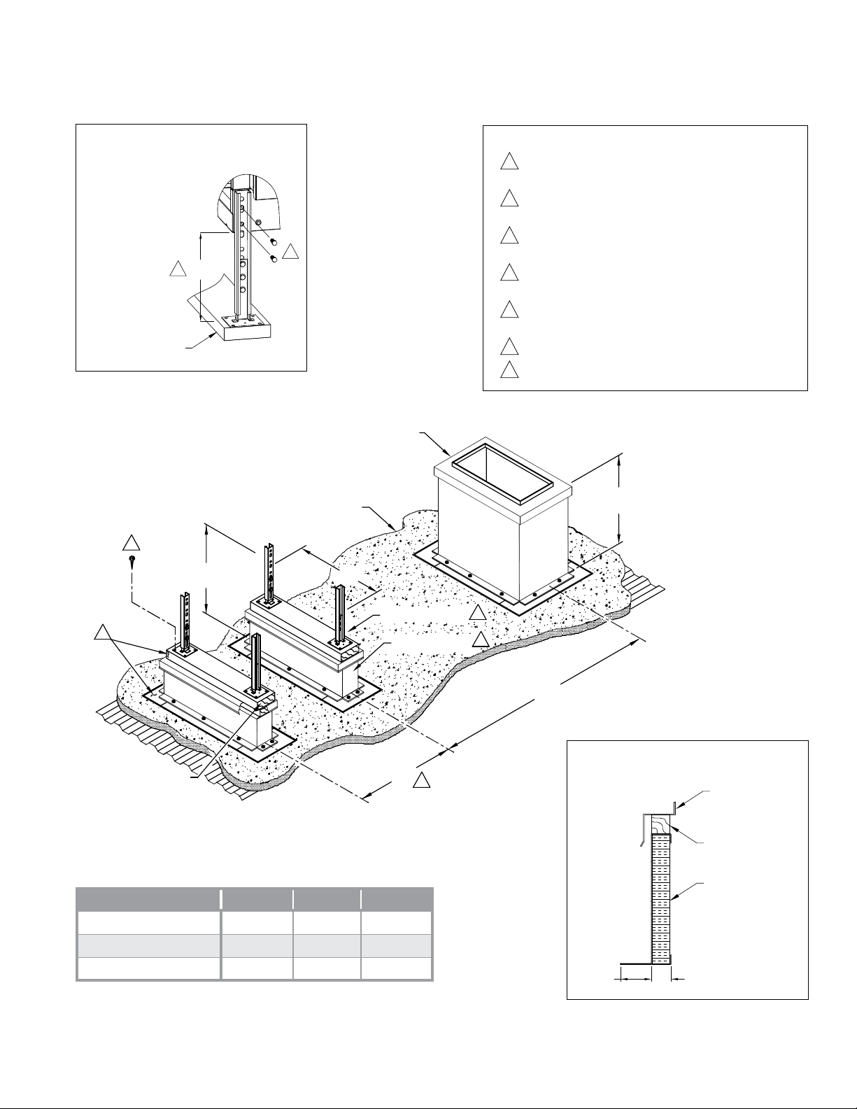
ROOF TOP MOUNTING - CURB / STAND / RAIL
STAND DETAIL
2 x 6 TREATED LUMBER
NOTES
1
TREATED TIMBER AS REQUIRED UNDER MOUNTING
CURB, RAIL AND STAND TO SECURE AND LEVEL UNIT.
2
SECURE MOUNTING STAND TO TIMBER WITH WOOD LAG
SCREWS AS SHOWN.
3
SECOND MOUNTING ASSEMBLY IS REQUIRED ONLY ON
6
10½"
7
DOWNTURN / CURB
WITH FLASHING
ROOF INSULATION
UNITS WITH FILTER SECTIONS.
4
MOUNTING STAND CONSTRUCTION:
12 GA. GALVANIZED STEEL
5
MOUNTING RAIL CONSTRUCTION:
18 GA. GALVANIZED STEEL
6
REMOVE HANGER BRACKET AND REPLACE SCREWS
7
ADJUSTABLE ± 3¾”
24"
REF.
2
TYP.
1
2 X 6 TREATED LUMBER
Model A B C
S400/S800
S950/S1200/S1600
S1850/S2200/S3200
24"
65½” 33¼” 25 3/8”
78 5/8” 33¼” 42”
90¼” 36¼” 47 1/8”
C
MOUNTING STAND
MOUNTING RAIL
B
3
4
5
A
CURB SECTION
FLASHING
2 x 2 WOOD NAILER
(PROVIDED)
INSULATION
S-Series Technical Manual 7 Cambridge Air Solutions
INSTALLATION INSTRUCTIONS
ROOF INSULATION
2 x 6 TREATED LUMBER
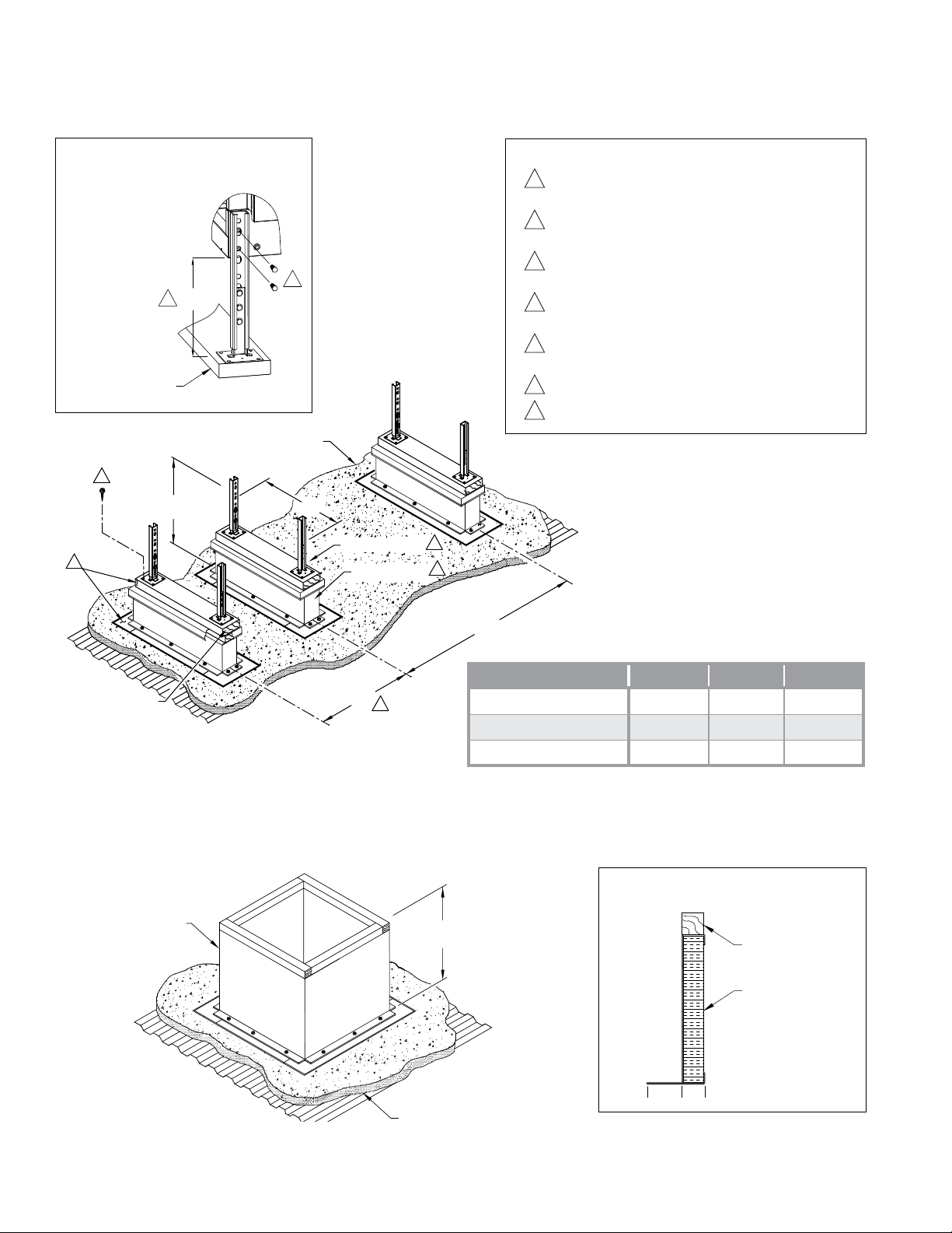
ROOF TOP / THRU WALL MOUNTING - STAND / RAIL
STAND DETAIL
2
1
7
TYP.
NOTES
1
TREATED TIMBER AS REQUIRED UNDER MOUNTING RAIL
AND STAND TO SECURE AND LEVEL UNIT.
2
SECURE MOUNTING STAND TO TIMBER WITH WOOD LAG
SCREWS AS SHOWN.
3
THIRD MOUNTING ASSEMBLY IS REQUIRED ONLY ON
6
10½"
ROOF INSULATION
24"
C
MOUNTING STAND
MOUNTING RAIL
4
5
UNITS WITH FILTER SECTIONS.
4
MOUNTING STAND CONSTRUCTION:
12 GA. GALVANIZED STEEL
5
MOUNTING RAIL CONSTRUCTION:
18 GA. GALVANIZED STEEL
6
REMOVE HANGER BRACKET AND REPLACE SCREWS
7
STAND IS ADJUSTABLE ±3¾”
2 X 6 TREATED LUMBER
B
3
UNDER ROOF MOUNTING - CURB
CURB
A
S400/S800
S950/S1200/S1600
S1850/S2200/S3200
24"
REF.
Model A B C
57 7/8” 33¼” 25 3/8”
69 7/8” 33¼” 42”
75¾” 36¾ ” 47 1/8”
CURB SECTION
2 x 2 WOOD NAILER
(PROVIDED)
INSULATION
Cambridge Air Solutions 8 S-Series Technical Manual
INSTALLATION INSTRUCTIONS
ROOF TOP MOUNTING
mWARNING:
Due to the size and weight of this equipment, it
is recommended the heater mounting structure
be reviewed and approved by a qualified
structural engineer and the roof manufacturer
before installing this equipment.
IMPORTANT
Before proceeding with the installation, verify the
feasibility of the location selected with respect to
accessibility for service and maintenance functions.
IMPORTANT
To minimize snow and rain ingestion, position the
heater inlet opposite the prevailing winds.
mCAUTION
To prevent contaminated air from being drawn
into the heater, install the heater’s inlet at least
10 feet from any building exhaust, process
exhaust, sewer stacks, or other sources that
would allow contaminants to be drawn into
the heater. Consult local codes for additional
references.
1. Prepare roof penetration to the dimensions below.
See page 6 for Roof Top Mounting - Curb/Stand/
Rail drawing.
IMPORTANT
Accurate measurements are critical and will affect
the installation process. Verify that the roof opening
aligns with the curb opening.
2. Secure the mounting curb and mounting rail(s) per
the structural engineer and roof manufacturer’s
recommendations.
IMPORTANT
The roof curb and mounting rail(s) should be
installed so that the heater will mount level.
Cambridge recommends mounting the heater a
minimum of 24” off the roof surface in areas where
snow accumulation could impact heater operations.
3. Attach the mounting stands to the heater while the
heater is on the ground. Adjust the height of the
stands so the heater inlet is slightly (1/8” below
level) lower than the discharge. This allows any
ingested moisture to drain out of the heater, through
weep holes located at the inlet of the heater, onto
the roof surface.
4. Lower the discharge duct through the mounting
curb and the roof opening and secure the
counterflashing to the mounting curb.
5. Use a crane or comparable lifting device to raise
and position the equipment. Use a spreader bar to
prevent damage and connect slings to the lifting
brackets.
mWARNING:
Do not attach lifting means to heater accessories.
Make connections to heater only.
IMPORTANT
Inlet accessories may be attached on the ground or
on the roof depending on the method chosen by the
installer.
6. Caulk all the joints between the heater and the
accessories with silicone caulk to prevent water
leaks.
IMPORTANT
Do not caulk the downturn/counterflashing for the
curb interface.
7. Seal all roof penetrations to prevent roof leaks.
8. Install the directional elbows. Consult the job
layout for the orientation of the elbows.
Roof Opening*
Model L W
S400/S800
S950/S1200/S1600
S1850/S2200/S3200
Weight
550 lbs. 13” 24¾”
800 lbs. 15” 41½”
1500 lbs. 24¼” 46½”
S-Series Technical Manual 9 Cambridge Air Solutions
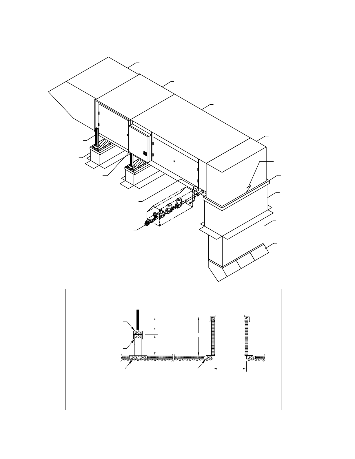
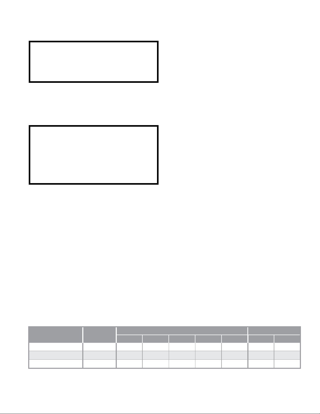
TYPICAL INSTALLATION
ROOF TOP MOUNTING
RAIN HOOD
FILTER SECTION
(OPTIONAL)
UNIT
ADJUSTABLE MOUNTING STAND
MOUNTING RAIL
ELECTRICAL CONTROL ENCLOSURE
(PROVIDED WITH EXTERNAL GAS TRAIN)
EXTERNAL GAS TRAIN WITH ENCLOSURE
(APPLICABLE TO SOME FM AND XL GAPS OPTIONS)
XL GAPS: FORMERLY IRI (INDUSTRIAL RISK INSURERS)
ELECTRICAL JUNCTION BOX
FM: FACTORY MUTUAL
CURB / RAIL / STAND DETAIL
DOWNTURN
NOTE:
DO NOT CAULK
THIS JOINT
COUNTERFLASHING
MOUNTING CURB
DISCHARGE DUCT
DIRECTIONAL
ELBOWS
2 X 6 TREATED LUMBER
2 X 4 TREATED LUMBER
(BY OTHERS)
(PROVIDED)
TREATED LUMBER
(BY OTHERS)
TREATED LUMBER (THICKNESS OF ROOF INSULATION) AS
REQUIRED UNDER MOUNTING STANDS AND CURB TO SECURE
AND LEVEL THE UNIT AND TO SPREAD THE LOAD. (BY OTHERS)
10½"
12"
TREATED LUMBER
(BY OTHERS)
24"
ROOF
OPENING
* Dimensions allow for ¾” clearance on each side
Cambridge Air Solutions 10 S-Series Technical Manual
INSTALLATION INSTRUCTIONS
THRU WALL MOUNTING
mWARNING:
Due to the size and weight of this equipment, it
is recommended the heater mounting structure be
reviewed and approved by a qualified structural
engineer before installing this equipment.
IMPORTANT
Before proceeding with the installation, verify the
feasibility of the location selected with respect to accessibility to the equipment for service and maintenance functions.
mCAUTION
To prevent contaminated air from being drawn into
the heater, install the heater’s inlet at least 10 feet
from any building exhaust, process exhaust, sewer
stacks, or other sources that would allow contaminants to be drawn into the heater. Consult local
codes for additional references.
1. Prepare wall penetration to the dimensions below.
2. Connect inlet accessories to the unit including
filter section (optional) and rain hood prior to lifting the heater in place. Note the inlet skirt for rain
hood (optional) is installed from the outside of the
building (page 20).
5. Use a forklift or comparable lifting device to
raise and position the heater. Take precautions
to prevent equipment damage (dents and/or
scratches) when the heater is being lifted into
position.
6. Use washers and double lock nuts to secure the
unit on the hanging rods.
IMPORTANT
The discharge end of the heater should be raised
slightly (1/8” above level). This allows any ingested
moisture to drain out of the heater through weep
holes located in the rain hood to the exterior of the
building.
7. Apply shims, by others, at the bottom of the rain
hood to take up slack in the opening, leaving a
small joint between the top of the rain hood and
the wall.
8. Install fiberglass insulation in the gaps around the
wall opening and the rain hood. Apply enough
material to accommodate the full thickness of the
wall.
9. Install finish trim pieces (by others) to the top,
sides and bottom of the rain hood on both the
inside and outside wall surfaces.
3. Install hanging rods to adequate ceiling supports
and align with the hanging brackets on the unit.
Refer to hanging rod size shown on table below.
Locate the hanging rods so that the weep holes
provided in the rain hood are located a minimum
of 3” beyond the outside wall surface.
4. Remove the lag bolts used to fasten the unit to the
skid. Do not remove the hanging brackets from the
side of the heater. On S400/S800 model heaters,
rotatethemountingbrackets180˚andretightenthe
securing hardware.
Model Qty. Size A B* C H W
S400/S800
S950/S1200/S1600
S1850/S2200/S3200
*Foroptionalltersection
** Dimensions allow for 1” clearance on each side
Weight
550 lbs. 4 (6*) 3/8” dia. 57 7/8” 33¼” 27 7/8” 26” 25½”
800 lbs. 4 (6*) 3/8” dia. 69 7/8” 33¼” 43 7/8” 29” 42¼”
1500 lbs. 4 (6*) 1/2” dia. 75¾” 36¾” 48 7/8” 38¾” 47¼”
10. Apply silicone caulk at the joint between the top
of the rain hood and the outside wall surface.
Make certain this is a continuous bead and that it
runs the entire width of the rain hood. Caulk all
other exposed joints.
11. Install the directional elbows. Consult the job
layout for the orientation of the elbows.
Hanging Rods Wall Opening**
S-Series Technical Manual 11 Cambridge Air Solutions
TYPICAL INSTALLATION
SHIPPING POSITION
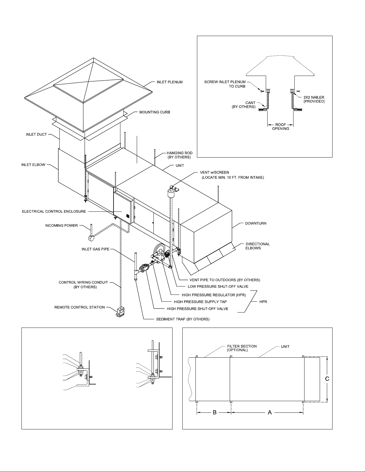
THRU WALL MOUNTING
RAINHOOD
EXTERIOR WALL TRIM
(BY OTHERS)
INTERIOR WALL TRIM
ELECTRICAL CONTROL ENCLOSURE
(LOCATE MIN. 10 FT. FROM INTAKE)
VENT w/SCREEN
(BY OTHERS)
INCOMING POWER
VENT PIPE TO OUTDOORS
(BY OTHERS)
CONTROL WIRING CONDUIT
INLET GAS PIPE
(BY OTHERS)
FILTER SECTION
(OPTIONAL)
UNIT
HANGING BRACKET
LOW PRESSURE SHUT-OFF VALVE
HIGH PRESSURE REGULATOR (HPR)
HANGING ROD
(BY OTHERS)
DOWNTURN
DIRECTIONAL
ELBOWS
HANGING ROD
NUT
WASHER
DOUBLE LOCK NUTS
WASHER
HANGING RODS, NUTS AND WASHERS BY OTHERS
L BRACKET
FOR S400 - S800 UNITS
REMOTE CONTROL STATION
HANGING ROD
NUT
WASHER
DOUBLE LOCK NUTS
WASHER
C BRACKET
FOR S950 - S3200 UNITS
HIGH PRESSURE SUPPLY TAP
HIGH PRESSURE SHUT-OFF VALVE
SEDIMENT TRAP
HANGING ROD DETAILHANGING BRACKET DETAIL
(OPTIONAL)
Cambridge Air Solutions 12 S-Series Technical Manual
INSTALLATION INSTRUCTIONS
ROOF TOP / THRU WALL MOUNTING
mWARNING:
Due to the size and weight of this equipment, it
is recommended the heater mounting structure be
reviewed and approved by a qualified structural
engineer and the roof manufacturer before
installing this equipment.
IMPORTANT
Before proceeding with the installation, verify the feasibility of the location selected with respect to accessibility to the equipment for service and maintenance
functions.
IMPORTANT
To minimize snow and rain ingestion, position the
heater inlet opposite the prevailing winds.
mCAUTION
To prevent contaminated air from being drawn
into the heater, install the heater’s inlet at least 10
feet from any building exhaust, process exhaust,
sewer stacks, or other sources that would allow
contaminants to be drawn into the heater. Consult
local codes for additional references.
1. Prepare wall penetration to the dimensions below.
See page 7 for Roof Top/Thru Wall Mounting
Stand/Rail drawing.
IMPORTANT
3. Attach the mounting stands to the heater while
the heater is on the ground. Adjust the height
of the stands so the heater inlet is slightly (1/8”
below level) lower than the discharge. This allows
any ingested moisture to drain out of the heater,
through weep holes located at the inlet of the heater, onto the roof surface.
4. Use a crane or comparable lifting device to raise
and position equipment. Use a spreader bar to
prevent damage and connect slings to the lifting
brackets.
mWARNING:
Do not attach lifting means to heater accessories.
Make connections to heater only.
IMPORTANT
Inlet accessories may be attached on the ground or
on the roof depending on the method chosen by the
installer.
5. Install the wall sleeve to the heater discharge.
6. Install fiberglass insulation in gaps around the wall
opening and wall sleeve. Apply enough material to
accommodate the full thickness of the wall.
7. Install finish trim pieces (by others) to top, sides
and bottom of the wall sleeve on both the inside
and outside wall surfaces.
Accurate measurements are critical and will affect
installation process.
2. Secure the mounting rails per the structural
engineer and roof manufacturer’s
recommendations.
IMPORTANT
The mounting rails should be installed so that the
heater will mount level. Cambridge recommends
mounting the heater a minimum of 24” off the roof
surface in areas where snow accumulation could
impact heater operations
Model H W
S400/S800
S950/S1200/S1600
S1850/S2200/S3200
1500 lbs. 27½” 50”
Weight
550 lbs. 16” 28¼”
800 lbs. 18” 45”
8. Apply silicone caulk at the joint between the top
of the wall sleeve and the outside wall surface.
Make certain this is a continuous bead and that it
runs the entire width of the wall sleeve. Caulk all
other exposed joints.
9. Seal all roof penetrations to prevent roof leaks.
10. Install the downturn and directional elbows.
Consult the job layout for the orientation of the
elbows.
Wall Opening*
S-Series Technical Manual 13 Cambridge Air Solutions
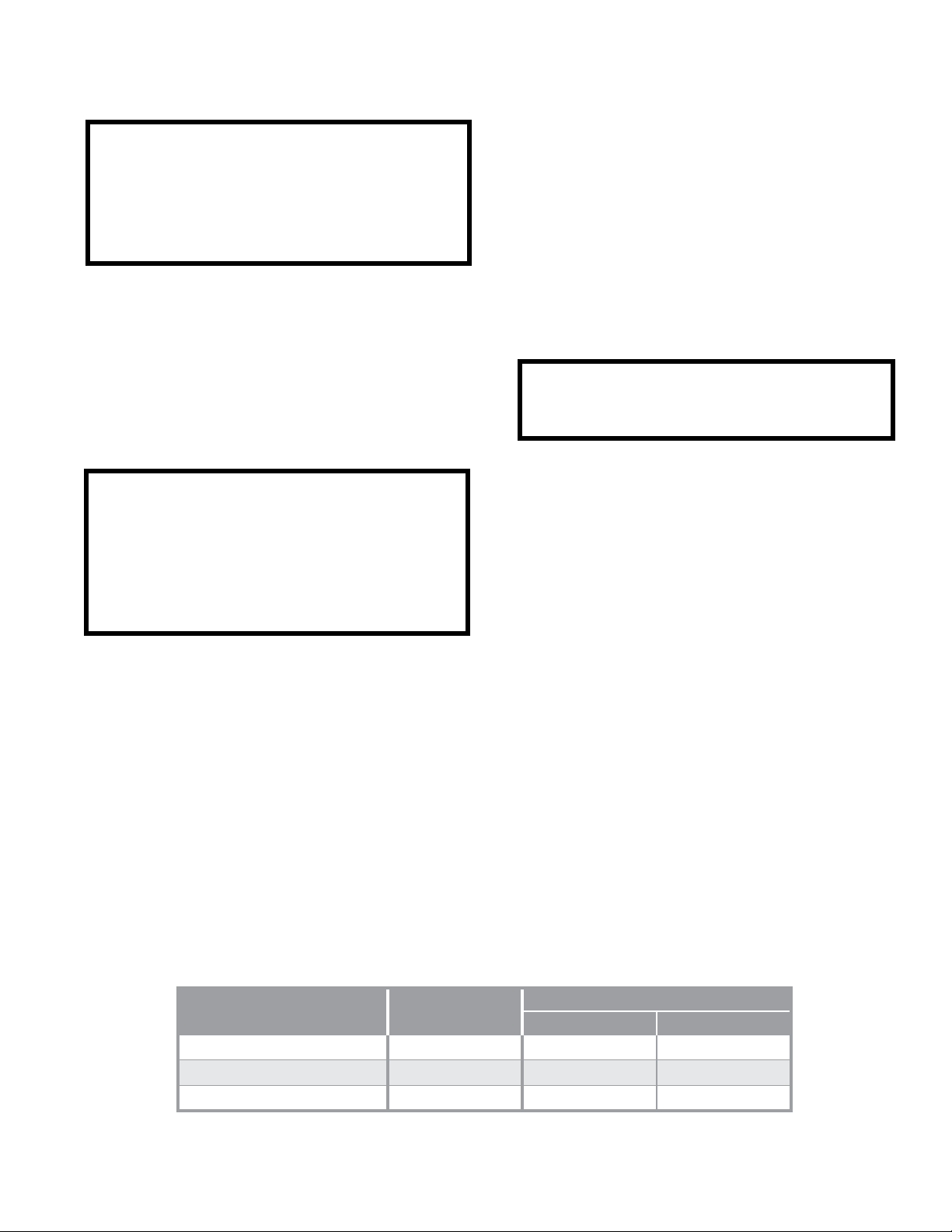
TYPICAL INSTALLATION
(BY OTHERS)
ROOF TOP / THRU WALL MOUNTING
RAIN HOOD
ADJUSTABLE MOUNTING STAND
MOUNTING RAIL
FILTER SECTION
(OPTIONAL)
UNIT
WALL SLEEVE
EXTERIOR WALL TRIM
(BY OTHERS)
INTERIOR WALL TRIM
(BY OTHERS)
ELECTRICAL CONTROL ENCLOSURE
(PROVIDED WITH EXTERNAL GAS TRAIN)
EXTERNAL GAS TRAIN WITH ENCLOSURE
(APPLICABLE TO SOME FM AND XL GAPS OPTIONS)
ELECTRICAL JUNCTION BOX
STAND DETAIL
2 X 6 TREATED LUMBER
2 X 4 TREATED LUMBER
(BY OTHERS)
(PROVIDED)
10½"
12"
DOWNTURN
DIRECTIONAL
ELBOWS
TREATED LUMBER
* Dimensions allow for 1½” clearance on each side
Cambridge Air Solutions 14 S-Series Technical Manual
INSTALLATION INSTRUCTIONS
UNDER ROOF MOUNTING
mWARNING:
Due to the size and weight of this equipment, it
is recommended the heater mounting structure be
reviewed and approved by a qualified structural
engineer and the roof manufacturer before
installing this equipment.
IMPORTANT
Before proceeding with the installation, verify the
feasibility of the location selected with respect to accessibility to the equipment for service and maintenance functions.
m CAUTION
To prevent contaminated air from being drawn
into the heater, install the heater’s inlet at least 10
feet from any building exhaust, process exhaust,
sewer stacks, or other sources that would allow
contaminants to be drawn into the heater. Consult
local codes for additional references.
IMPORTANT
The mounting curb or mounting structure should
be installed such that the heater’s inlet plenum will
mount level.
3. Seal all roof penetrations to prevent roof leaks.
4. Lower the inlet duct through the mounting curb
and the roof opening.
5. Secure the inlet plenum to the curb.
6. Connect inlet accessories to the heater including
filter section (optional) and inlet elbow prior to
lifting the heater in place.
7. Install hanging rods to adequate ceiling supports
and align with the hanging brackets on the heater.
Refer to hanging rod size shown on table below.
8. Remove the lag bolts used to fasten the unit to the
skid. Do not remove the hanging brackets from the
side of the heater. On S400/S800 model heaters,
rotatethehangingbrackets180˚,andretightenthe
securing hardware.
1. Prepare roof penetration to the dimensions below.
See page 7 for Under Roof Mounting - Curb drawing
IMPORTANT
Accurate measurements are critical and will affect
the installation process. Verify that the roof opening
aligns with the curb opening.
2. Install the mounting curb and the mounting structure per the structural engineer and roof manufacturer’s recommendations.
Model Qty. Size A B* C L W
S400/S800
S950/S1200/S1600
S1850/S2200/S3200
*Foroptionalltersection
** Dimensions allow for ¾” clearance on each side
Weight
550 lbs. 4 (6*) 3/8” dia. 57 7/8” 33¼” 27 7/8” 25” 25”
800 lbs. 4 (6*) 3/8” dia. 69 7/8” 33¼” 43 7/8” 30” 41¼”
1500 lbs. 4 (6*) 1/2” dia. 75¾” 36¾” 48 7/8” 37¼” 46¾”
9. Use a forklift or comparable lifting device to
raise and position the heater. Take precautions
to prevent equipment damage (dents and/or
scratches) when the heater is being lifted into
position.
10. Use washers and double lock nuts to secure
equipment on the hanging rods.
11. Install the directional elbows. Consult the job
layout for the orientation of the elbows.
Hanging Rods Roof Opening**
S-Series Technical Manual 15 Cambridge Air Solutions
TYPICAL INSTALLATION
SHIPPING POSITION
UNDER ROOF MOUNTING
CURB DETAIL
FILTER SECTION (OPTIONAL)
TREATED LUMBER (THICKNESS OF ROOF INSULATION) AS
REQUIRED UNDER MOUNTING CURB TO SECURE AND LEVEL
THE UNIT AND TO SPREAD THE LOAD. (BY OTHERS)
DOUBLE LOCK NUTS
FOR S400 - S800 UNITS
Cambridge Air Solutions 16 S-Series Technical Manual
HANGING ROD
NUT
WASHER
WASHER
DOUBLE LOCK NUTS
HANGING RODS, NUTS AND WASHERS BY OTHERS
L BRACKET
FOR S950 - S3200 UNITS
HANGING ROD
NUT
WASHER
WASHER
C BRACKET
HANGING ROD DETAILHANGING BRACKET DETAIL
INSTALLATION INSTRUCTIONS
VERTICAL INDOOR MOUNTING
mWARNING:
Due to the size and weight of this equipment, it
is recommended the heater mounting structure be
reviewed and approved by a qualified structural
engineer before installing this equipment.
IMPORTANT
Before proceeding with the installation, verify the
feasibility of the location selected with respect to accessibility to the equipment for service and maintenance functions.
m CAUTION
To prevent contaminated air from being drawn
into the heater, install the heater’s inlet at least 10
feet from any building exhaust, process exhaust,
sewer stacks, or other sources that would allow
contaminants to be drawn into the heater. Consult
local codes for additional references.
1. Prepare wall penetration to the dimensions below.
2. Connect the inlet accessories to the heater including
the filter section (optional), the inlet elbow and the
rain hood prior to standing the heater upright. Note
the inlet skirt for the rain hood (optional) is installed
from the outside of the building (page 20).
3. Install hanging rods to adequate ceiling and/or wall
supports per the structural engineer’s recommendations and align with the hanging brackets on the
heater. Refer to the hanging rod size shown on the
table below. Locate the hanging rods so that the
weep holes provided in the rain hood are located a
minimum of 3” beyond the outside wall surface.
4. Remove the lag bolts used to fasten the unit to the
skid. Rotate the hanging brackets for the vertical
application and retighten the securing hardware.
5. Utilizing the lifting brackets on the front of the heater,
use a forklift or comparable lifting device to raise
and position the heater. Take precautions to prevent
equipment damage (dents and/or scratches) when the
heater is being lifted into position.
6. Use washers and double lock nuts to secure
equipment on hanging rods.
IMPORTANT
The rain hood should be sloped slightly (1/8” off
level). This allows any ingested moisture to drain out
of the heater through weep holes located in the rain
hood to the exterior of the building.
7. Apply shims at the bottom of the rain hood to take up
slack in the opening, leaving a minimal joint between
the top of the rain hood and the wall.
8. Install fiberglass insulation in the gaps around the
wall opening and the rain hood. Apply enough
material to accommodate the full thickness of the
wall.
9. Install finish trim pieces (by others) to the top, sides
and bottom of the rain hood on both the inside and
outside wall surfaces.
10. Apply silicone caulk at the joint between the top
of the rain hood and the outside wall surface.
Make certain this is a continuous bead and that it
runs the entire width of the rain hood. Caulk all
other exposed joints.
11. Install the second downturn and directional
elbows. Consult the job layout for the orientation
of the elbows.
Model Weight
S400/S800
S950/S1200/S1600
S1850/S2200/S3200
Qty. Size A B H W
650 lbs. 4 3/8” dia. 23 3/8” 27 7/8” 26” 25½”
950 lbs. 4 3/8” dia. 26” 43 7/8” 29” 42¼”
1750 lbs. 4 1/2” dia. 34 7/8” 48 7/8” 38¾” 47¼”
Hanging Rods Wall Opening*
S-Series Technical Manual 17 Cambridge Air Solutions
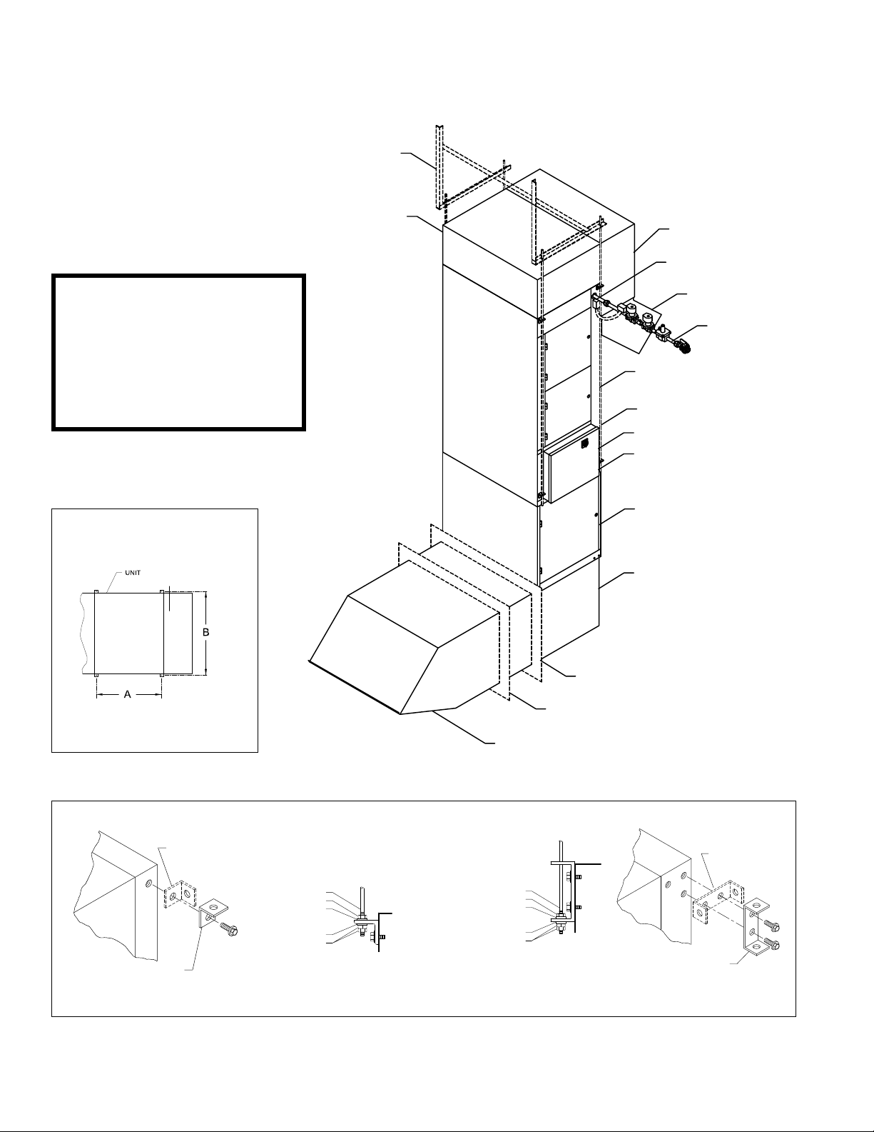
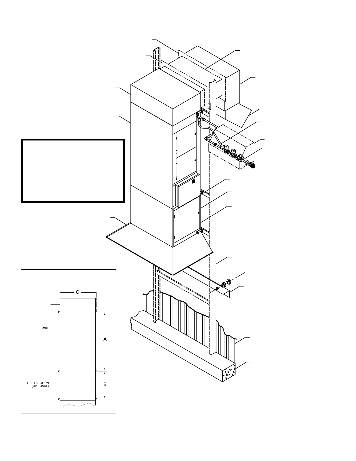
TYPICAL VERTICAL INDOOR INSTALLATION
STRUCTURAL
KNEE BRACE
(BY OTHERS)
mWARNING:
The primary structural support
element of a vertically mounted
heater is the base. Any support
to the heater cabinet should be
considered secondary, only as a
means to help stabilize the heater.
HANGING ROD DETAIL
SECOND DOWNTURN
(OPTIONAL)
DOWNTURN
DOWNTURN
SECOND DOWNTURN
(OPTIONAL)
GAS TRAIN WIRING
(FIELD CONNECTED)
DIRECTIONAL
ELBOWS
GAS TRAIN
HANGING ROD
(BY OTHERS)
UNIT
BASE OF HEATER
ELECTRICAL CONTROL
ENCLOSURE
FILTER SECTION
(OPTIONAL)
INLET ELBOW
INTERIOR WALL TRIM
(BY OTHERS)
EXTERIOR WALL TRIM
(BY OTHERS)
RAIN HOOD
HANGING BRACKET DETAIL
SHIPPING POSITION
DOUBLE LOCK NUTS
MOUNTING POSITION
L BRACKET
FOR S400 - S800 UNITS
* Dimensions allow for 1” clearance on each side
HANGING RODS, NUTS AND WASHERS BY OTHERS
HANGING ROD
NUT
WASHER
WASHER
HANGING ROD
NUT
WASHER
WASHER
DOUBLE LOCK NUTS
SHIPPING POSITION
MOUNTING POSITION
C BRACKET
FOR S950 - S3200 UNITS
Cambridge Air Solutions 18 S-Series Technical Manual

INSTALLATION INSTRUCTIONS
VERTICAL OUTDOOR MOUNTING
mWARNING:
Due to the size and weight of this equipment, it
is recommended the heater mounting structure be
reviewed and approved by a qualified structural
engineer before installing this equipment.
IMPORTANT
Before proceeding with the installation, verify the
feasibility of the location selected with respect to accessibility to the equipment for service and maintenance functions.
mCAUTION
To prevent contaminated air from being drawn
into the heater, install the heater’s inlet at least 10
feet from any building exhaust, process exhaust,
sewer stacks, or other sources that would allow
contaminants to be drawn into the heater. Consult
local codes for additional references.
1. Prepare wall penetration to the dimensions below.
2. Connect the inlet accessories to the heater including the filter section (optional).
7. Install the wall sleeve to the downturn.
8. Install fiberglass insulation in the gaps around the
wall opening and the wall sleeve. Apply enough
material to accommodate the full thickness of the
wall.
9. Install finish trim pieces (by others) to the top,
sides and bottom of the wall sleeve on both the
inside and outside wall surfaces.
10. Apply silicone caulk at the joint between the wall
sleeve and the outside wall surface. Make certain
this is a continuous bead and that it runs the entire
width of the wall sleeve. Caulk all other exposed
joints.
11. Mount the gas train enclosure to the wall structure
and connect gas piping between the heater and the
enclosure.
12. Install the inlet skirt to the heater inlet and attach
the skirt extension to the exterior wall (page 21).
13. Install wall sleeve, second downturn and
directional elbows. Consult the job layout for the
orientation of the elbows.
3. Install structural uprights and associated wall supports per structural engineers recommendations.
4. Remove the lag bolts used to fasten the unit to the
skid.
5. Utilizing the lifting brackets on the front of the
heater, use a forklift or comparable lifting device
to raise and position the heater. Take precautions to prevent equipment damage (dents and/or
scratches) when the heater is being lifted into position.
6. Secure the heater in place with contractor supplied
hardware.
* Dimensions allow for 1½” clearance on each side
S-Series Technical Manual 19 Cambridge Air Solutions
TYPICAL VERTICAL OUTDOOR INSTALLATION
INTERIOR WALL FLASHING
(BY OTHERS)
EXTERIOR WALL FLASHING
(BY OTHERS)
DOWNTURN
UNIT
mWARNING:
The primary structural support
element of a vertically mounted
heater is the base. Any support
to the heater cabinet should be
considered secondary, only as a
means to help stabilize the heater.
WALL SLEEVE
SECOND DOWNTURN
(OPTIONAL)
DIRECTIONAL
ELBOWS
GAS TRAIN WIRING
(FIELD CONNECTED)
GAS TRAIN ENCLOSURE
GAS TRAIN
ELECTRICAL CONTROL ENCLOSURE
BASE OF HEATER
INLET SKIRT
(FIELD ASSEMBLED)
MOUNTING DETAIL
DOWNTURN
FILTER SECTION
(OPTIONAL)
CHANNEL SUPPORT
(BY OTHERS)
SECURE STRUCTURAL CHANNEL
TO WALL (AS REQUIRED)
(BY OTHERS)
BUILDING WALL
BUILDING FOOTING
Cambridge Air Solutions 20 S-Series Technical Manual
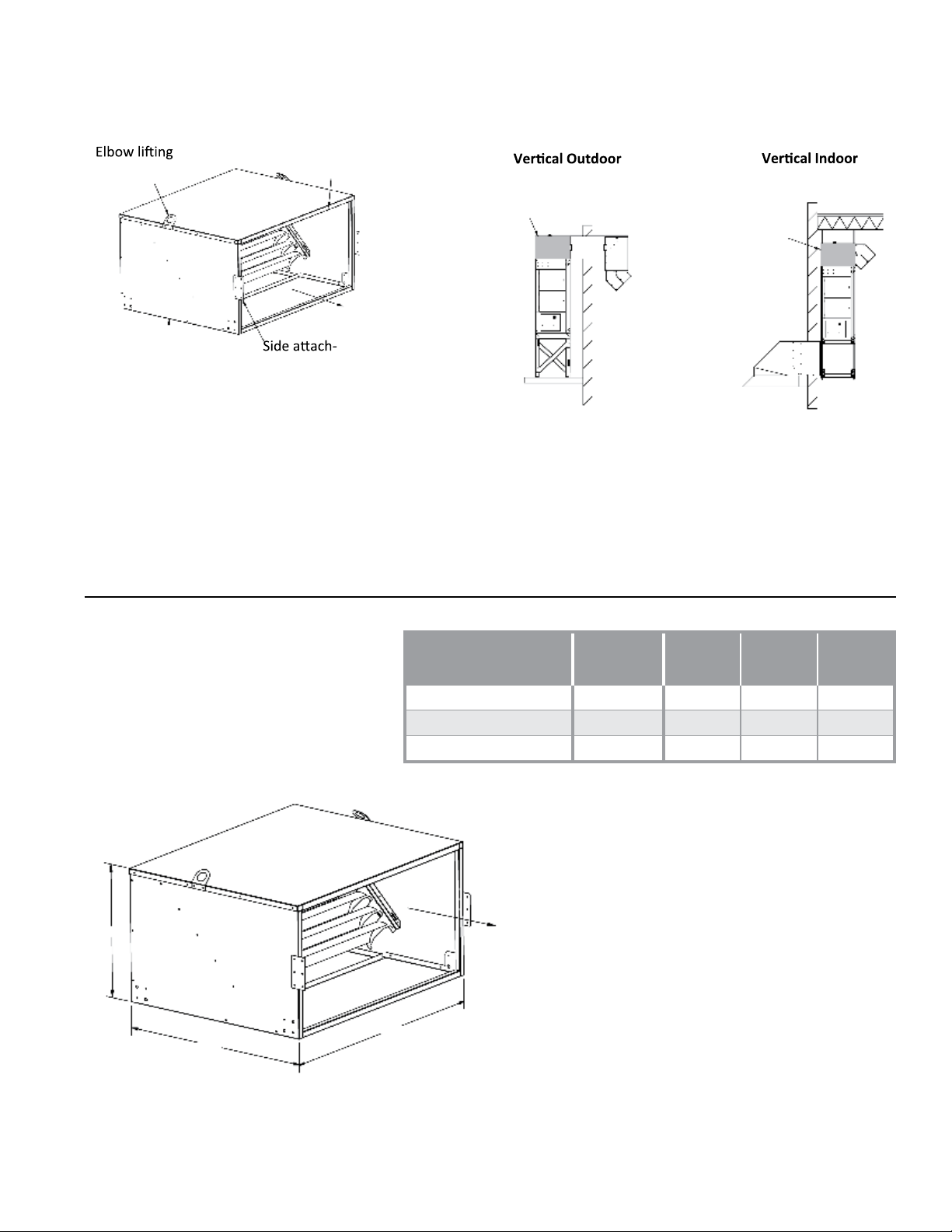
INSTALLATION INSTRUCTIONS
brackets (4 plcs)
Airflow
Stand-Mounted
Structural
inlet elbow
Floor-Mounted
Structural
inlet elbow
Ceiling-Mounted
Structural
inlet elbow
Retaining clip
Retaining clip
(downblast
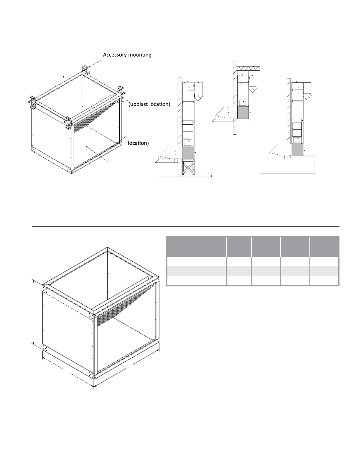
VERTICAL S-SERIES STRUCTURAL INLET ELBOW
Ceiling-Mounted
brackets (4 plcs)
Stand-Mounted
Retaining clip
Structural
Retaining clip
(downblast
Airflow
The vertical S-Series structural inlet elbow is suitable for indoor or outdoor use. The elbow has been structurally
reinforced to support the weight of the unit and any additional accessories applicable to your installation. It can be
used in floor-mounted applications, with or without a stand, as well as ceiling-mounted applications when hanging
the unit with threaded rod. The elbow is insulated to prevent condensation and reduce noise levels.
Structural
inlet elbow
Model Weight A B C
inlet elbow
Floor-Mounted
Structural
inlet elbow
A
S400/S800
S950/S1200/S1600
S1850/S2200/S3200
C
B
150 lbs. 27 1/2” 25 3/8” 25 3/8”
205 lbs. 30 3/4” 28” 42”
300 lbs. 40 3/8” 37 3/8” 47 1/8”
S-Series Technical Manual 21 Cambridge Air Solutions
INSTALLATION INSTRUCTIONS
Ø 5/8” holes for
wall support
Accessory
bracket
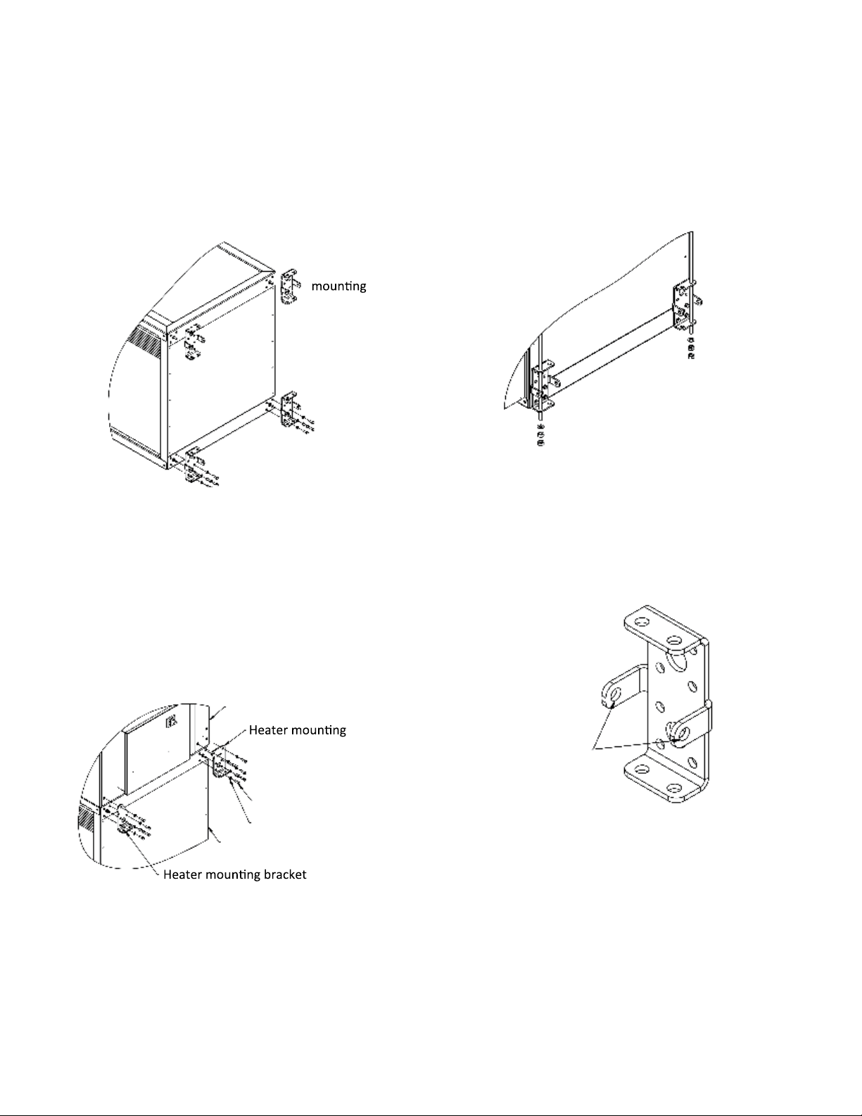
VERTICAL S-SERIES STRUCTURAL INLET ELBOW
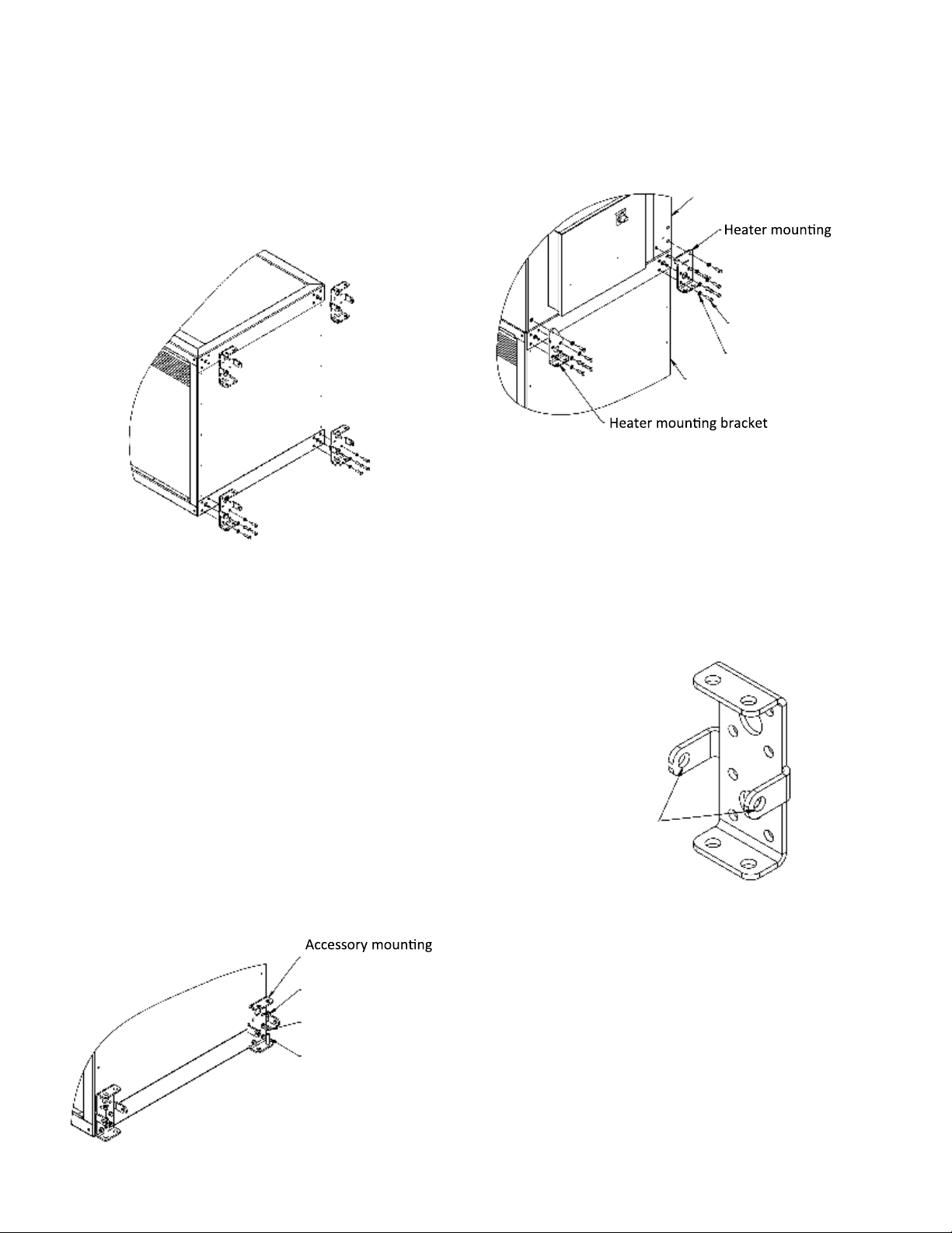
CEILING-MOUNTED APPLICATIONS
1. Remove the accessory mounting brackets from the top
of the inlet elbow and reattach them on the bottom of
the inlet elbow for hanging.
Accessory
bracket
2. If heater is vertical downblast, remove the retaining
clip and attach to the opposite flange. .
3. Use the included heater mounting brackets to attach
the inlet elbow to the heater (or filter section if
applicable).
6. Secure threaded rod to ceiling structure as needed.
7. Double-nut the end of the rod below the mounting
bracket at the bottom of the inlet elbow.
8. It is recommended to run support back to the wall to
prevent swaying or tipping of heater and accessories.
• Use the provided holes in the mounting brackets to
run threaded rod (by others) to support on walls (by
others).
• If filter section is included, attach heater to filter
sec-tion using provided accessory mounting brackets
after inlet elbow and filter section are connected.
Heater
bracket
Bolts
Lock washers
Structural inlet elbow
4. If not already attached, secure elbow to discharge of
heater using provided heater mounting brackets.
5. Position heater with attached accessories upright and
lift into place.
Ø 5/8” holes for
wall support
9. For indoor installations, attach thru-wall rain hood and
inlet skirt if applicable.
Cambridge Air Solutions 22 S-Series Technical Manual
INSTALLATION INSTRUCTIONS
Ø 5/8” holes for
wall support
Structural inlet
elbow
Accessory
bracket
Adjustable stand
Bolt
Lock washer
Ø 5/8” holes for
wall support
VERTICAL S-SERIES STRUCTURAL INLET ELBOW
STAND-MOUNTED APPLICATIONS
1. Once the stand is set, attach inlet elbow to stand using
the provided accessory mounting brackets.
Structural inlet
elbow
Accessory
bracket
Adjustable stand
Bolt
Lock washer
2. If filter section included, attach filter section to
inlet elbow using the provided accessory mounting
brackets. If filter section is not included, skip to
step 3.
3. Attach heater to inlet elbow (or filter section) below
using the provided heater mounting brackets.
5. It is recommended to run support back to the wall to
prevent swaying or tipping of heater and accessories.
• Use the provided holes in the mounting brackets to
run threaded rod (by others) to support on walls (by
others).
Ø 5/8” holes for
wall support
6. For indoor installations, attach thru-wall rain hood and
inlet skirt if applicable.
Heater
bracket
Bolts
Lock washers
Structural inlet elbow
4. Continue attaching discharge accessories with
provided mounting brackets as needed.
S-Series Technical Manual 23 Cambridge Air Solutions
INSTALLATION INSTRUCTIONS
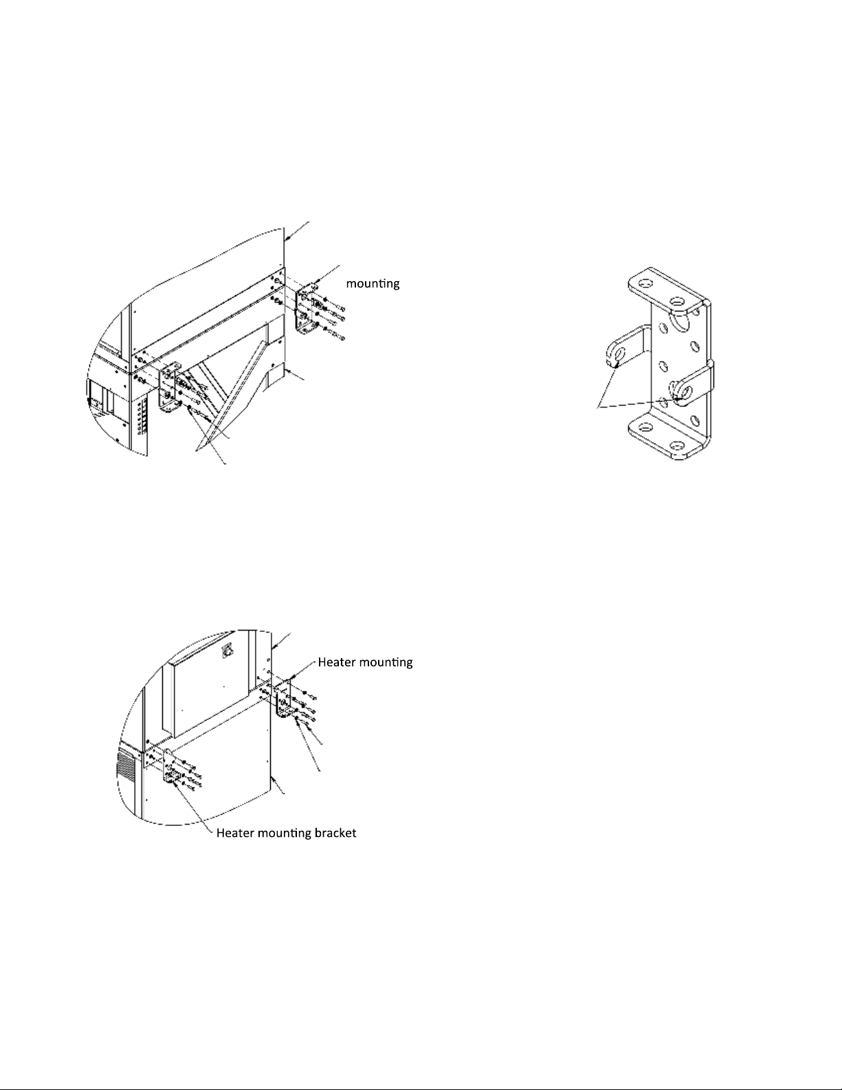
Ø 5/8” holes for
wall support
Heater
bracket
Bolts
Lock washers
Structural inlet elbow
Heater
bracket
Bolts
Lock washers
Structural inlet elbow
Heater
bracket
Bolts
Lock washers
Structural inlet elbow
VERTICAL S-SERIES STRUCTURAL INLET ELBOW
FLOOR-MOUNTED APPLICATIONS
1. Remove the mounting brackets from the top of the
inlet elbow and reattach them on the bottom of the
inlet elbow for anchoring to the floor.
2. Determine the distance needed between the building
wall and the heater.
3. Place inlet elbow where desired and mark anchor locations using holes in the attached mounting brackets.
9. Continue attaching discharge accessories to heater as
needed using the provided mounting brackets.
Heater
bracket
Bolts
10. It is recommended to run support back to the wall to
prevent swaying or tipping of heater and accessories.
• Use the provided holes in the mounting brackets to
run threaded rod (by others) to support on walls (by
others).
Lock washers
Structural inlet elbow
11. For indoor installations, attach thru-wall rain hood
and inlet skirt if applicable.
4. Install wedge anchors, minimum 0.5”x6” (not
provided), as recommended by manufacturer into
concrete floor where marked.
5. Set inlet elbow over anchors.
6. Make sure inlet elbow is level using shims (by others)
if necessary.
7. Once level, secure elbow to anchors with washer and
Ø 5/8” holes for
wall support
lock nut (not provided).
8. Attach heater (or filter section if applicable) to inlet
elbow using the provided mounting brackets.
bracket
Anchor lock nut
Washer
Installed anchor
Cambridge Air Solutions 24 S-Series Technical Manual
INSTALLATION INSTRUCTIONS
Non-adjustable elbows
Non-adjustable
elbows
Airflow
ment plates
Retaining clip
VERTICAL S-SERIES NON-ADJUSTABLE ELBOW
brackets (Qty 2)
Airflow
Retaining clip
Non-adjustable elbows
ment plates
The non-adjustable elbow is suitable for discharge ductwork to turn air 90° for either indoor or outdoor S-Series
installations. It attaches to the discharge end of a vertical heater or vertical duct extensions with 4 accessory
Non-adjustable
elbows
mounting brackets (shipped with the heater or vertical duct extension) that can either be suspended via threaded
hanging rod or secured horizontal to the wall in stand mounted applications. The discharge end of the elbow attaches
easily to wall sleeves or downturns with lugs. directional elbows with a discharge collar can also be attached directly
to the non-adjustable elbow if desired. Non-adjustable elbows are insulated to help mitigate noise and thermal losses.
A
Model Weight A B C
S400/S800
S950/S1200/S1600
S1850/S2200/S3200
Airflow
C
B
45 lbs. 13” 25 3/8” 25 3/8”
75 lbs. 15” 28” 42”
130 lbs. 24 5/8” 37 1/2” 47”
S-Series Technical Manual 25 Cambridge Air Solutions
INSTALLATION INSTRUCTIONS
Non-adjustable elbow
Non-adjustable elbow
Wall sleeve
Non-adjustable
elbow
Accessory
bracket
Heater
Retaining clip
Non-adjustable elbow
Discharge collar
Non-adjustable elbow
ment plates
Wall sleeve
Non-adjustable elbow
Non-adjustable elbow
ment plates
Wall sleeve
Non-adjustable elbow
Wall sleeve
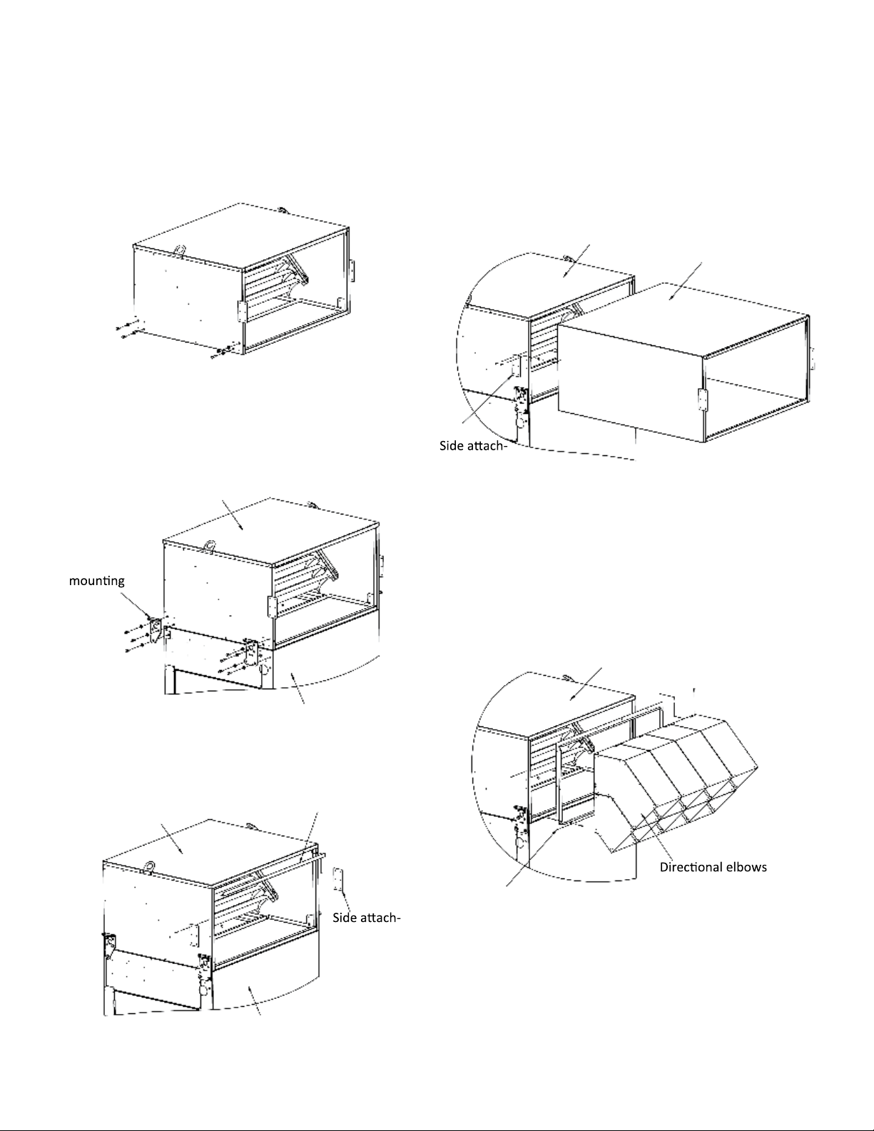
VERTICAL S-SERIES NON-ADJUSTABLE ELBOW
1. Prepare the non-adjustable elbow for assembly by
re moving the bolts and washers from the sides.
For ceiling mounted applications please refer to the
installation instructions for the structural inlet elbows.
2. Prepare the upstream accessory or heater by removing
the accessory mounting brackets.
3. Lift the non-adjustable elbow into place and secure it
using the bolts and washers removed in the previous
step.
Accessory
bracket
Non-adjustable
elbow
5a. If attaching a wall sleeve or a downturn with lugs,
secure it using both the retaining clip and side
attachment plates. Follow additional installation steps
detailed in the appropriate accessory installation
instructions.
Non-adjustable elbow
Wall sleeve
ment plates
5b. If attaching a discharge collar and directional elbows
replace the screws removed in step 4. Attach the
dis-charge collar to the discharge face of the nonadjustable elbow and secure using self-tapping
screws. Arrange the directional elbows in the desired
configu-ration before securing them to the discharge
collar.
Heater
4. If not already done, remove the side attachment plates
from the discharge end of the non-adjustable elbow. If
attaching a discharge collar with directional elbows,
also remove the retaining clip.
Non-adjustable
elbow
ment plates
Discharge collar
6. Seal all seams between heater and accessories
using appropriate contractor grade caulk to mitigate
Heater
potential water ingestion and pressure loss.
Cambridge Air Solutions 26 S-Series Technical Manual
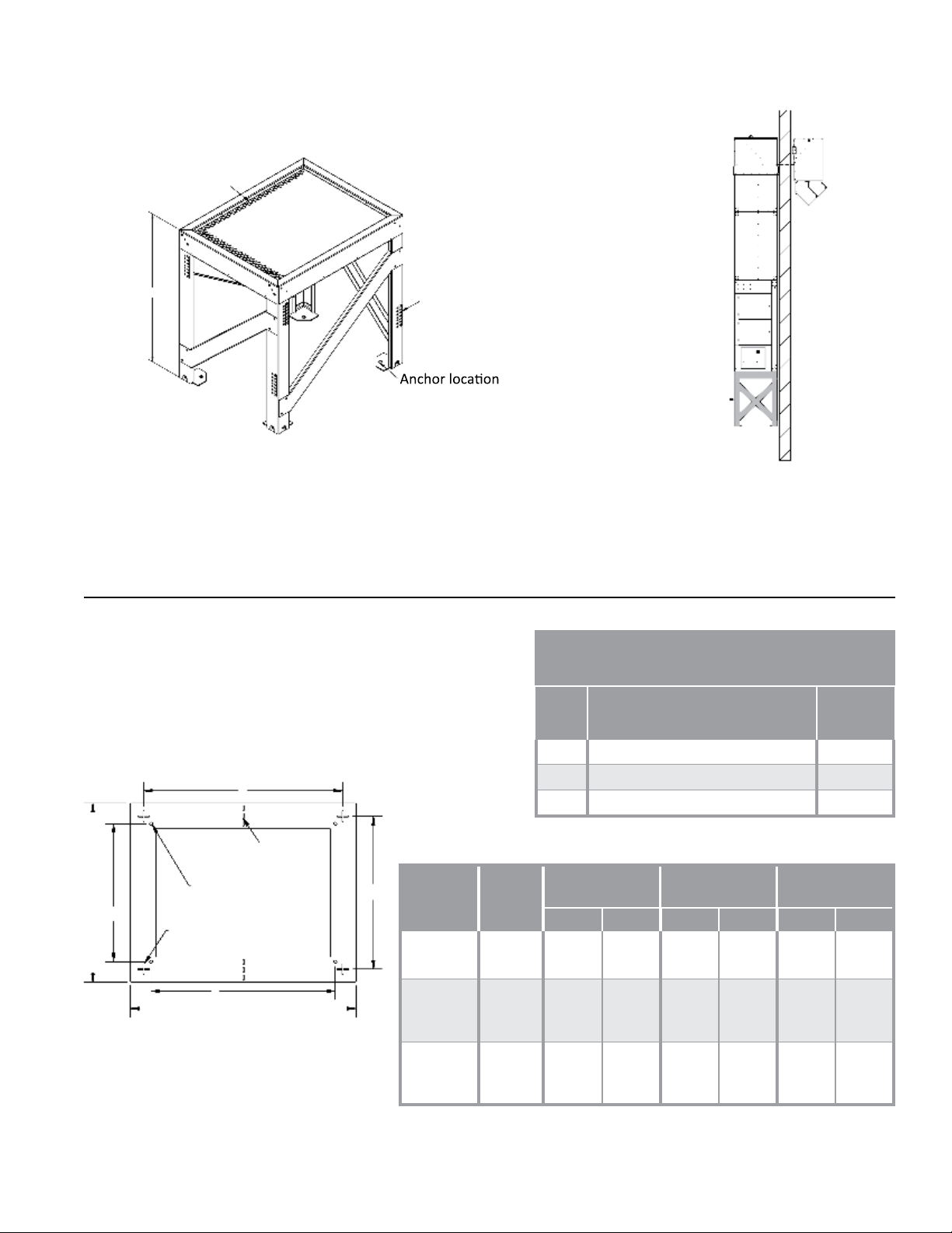
INSTALLATION INSTRUCTIONS
Adjustable
stand
Height adjustment
label (2/leg)
(4 plcs)
48”-54”
Inlet screen
VERTICAL S-SERIES ADJUSTABLE STAND
Inlet screen
48”-54”
Height adjustment
label (2/leg)
(4 plcs)
Adjustable
stand
The Vertical S-Series Adjustable Stand is suitable for use in the up blast configuration in both indoor and outdoor
locations. The 48” height is low enough so the control can may still be accessible without lifts or ladders, but high
enough to avoid snow ingestion from the ground during winter months. The stand features 6” of adjustment (up to
54”) and is suitable for applica-tions when you prefer the heater to be easily accessible for service, yet floor space or
slab size may come at a premium.
1. Determine distance needed between building wall and
heater (12” recommended).
Parts List
• Outer edge of template matches footprint of vertical
unit and stand w/ centerline of heater indicated.
Item Description Qty.
Adjustable stand (assembled) 1
Template 1
Leveling shims 20
Anchor
Footprint
A B C D E F
Locations (o)
Sonotube
Locations (+)
A
1
Template Detail
E
Centerline
Anchor center
C
Sonotube center
D
B
F
Stand
Size
S400/
S800
S950/
S1200/
S1600
S1850/
S2200/
S3200
Weight
176 lbs. 25 1/2” 25 1/2” 16 3/4” 16 3/4” 19 7/8” 19 7/8”
196 lbs. 28” 42” 19 1/2” 33 1/2” 36 1/2” 22 1/2”
222 lbs. 37 1/2” 47” 28 7/8” 38 1/2” 41 5/8” 32”
2
3
Heater/Stand
S-Series Technical Manual 27 Cambridge Air Solutions

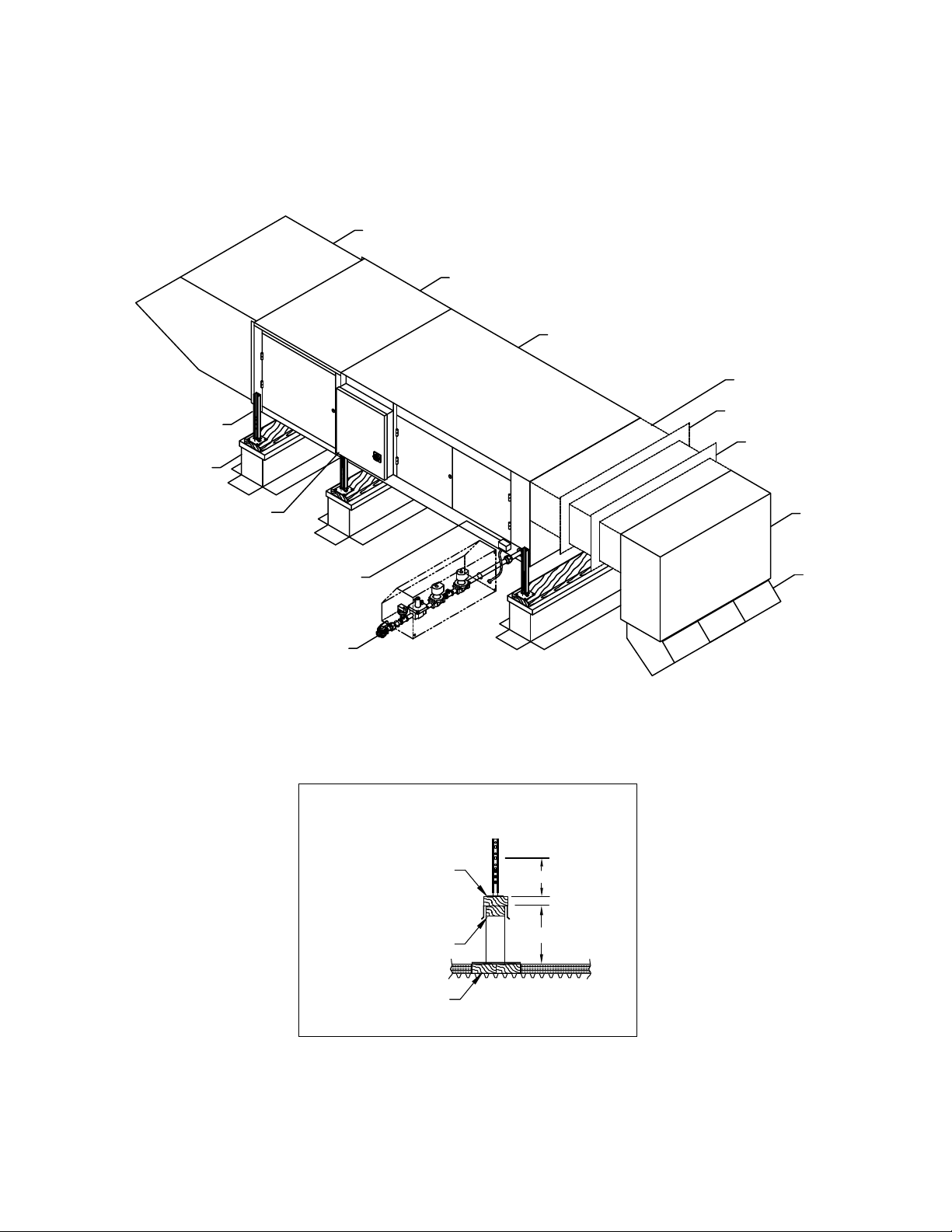
INSTALLATION INSTRUCTIONS
Anchor lock nut
Washer
Stand shim
Stand leg
Anchor lock nut
Washer
Stand shim
Stand leg
VERTICAL S-SERIES ADJUSTABLE STAND
2. Use provided template to mark anchor locations on
existing concrete slab. Consult structural engineer as
to adequacy of existing slab for structural support.
• If no slab available, installation of sonotubes with
housekeeping pad is recommended. Use template to
mark center locations of sono-tubes (indicated with
”+” cutout).
• Install sonotubes as recommended by struc-tural
engineer and use template to mark an-chor locations
(indicated with ”o” hole) on sonotubes.
Anchor-
holes
Drilled holes for
anchors
Template
Centerline
Sonotube-
cutouts
Concrete slab
7. Make sure stand is both level and square.
• If shimming necessary, insert provided shims where
needed to level the stand.
• Once level and square, secure base to anchors with
washer and lock nut (not provided).
• Shims are NOT intended to be used for ad-justing
the overall stand height. See next step.
Anchor lock nut
Stand leg
Washer
Stand shim
8. Determine if default stand height (48”) is correct for
heater installation.
• If adjustment needed, remove height adjust-ment
bolts (2/leg), and raise stand necessary amount using
the height label as a guide.
3. Once concrete/sonotubes are marked, remove and
discard template.
4. Drill holes for anchors.
5. Set stand over anchor locations.
6. Install outdoor rated wedge anchors, minimum
0.5”x6” (not provided), as recommended by
manufacturer into concrete slab/sonotubes where
marked.
• Reattach height adjustment bolts.
Washer
Height
adjustment
bolt (2/leg)
Height label
Nut
Lock washer
Cambridge Air Solutions 28 S-Series Technical Manual
 Loading...