

Cambo CS-32, CS-33, CS-34 Instruction Manual
Instruction Manual CS-
31> Camera Mounting Frame
1
CS-32/33/34
CAMERA MOUNTING SYSTEM CS-30 VIEWING LOUPE
INSTRUCTION MANUAL
EN
Please read this manual carefully before using the Cambo CS-31> system!
Warnings
!!!!
CAUTION
(when using the CS-30 loupe)
Avoid exposure off direct sunrays on the loupe, the loupe (convex lens) acts as a burning-
glass and will damage the LCD surface.
Only “click off” the CS-30 loupe sideways, thus from “left to right” or from “right to left”, DO NOT
“click off” the loupe “top to bottom” or “bottom to top”, this will damage the CS-30 housing.
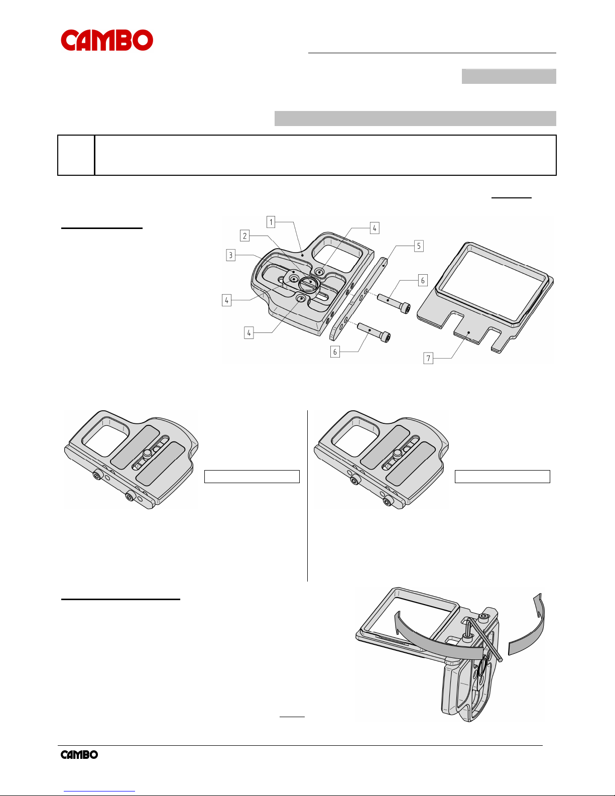
Overview parts
1 Base Plate
2 Camera Screw (1/4” 20 WW)
3 Screw Offset Adapter
4 Mounting Hole (1/4” 20 WW)
5 Clamp Plate (of the frame)
6 Hex Screw
7 Mounting Frame CS-30 Loupe
(The image shows the CS-33 high frame)
8 Hex key (3mm DIN911)
To increase the compatibility with different camera bodies, the “clamp plate” can be mounted in two different
positions, according the images below. The positions of the “hex screws” relate to a particular camera model and
frame type. The camera models, “screw positions” and “frame type” are stated below.
●
= Hex screw
○
= Empty hole
L
= Left
R
= Right
● ○ ● ○
L
L
●
= Hex screw
○
= Empty hole
L
= Left
R
= Right
○ ● ○ ●
R
R
Camera model Screw position Frame type
Canon 1D MKIV Left-Left CS-34 1D frame
Canon 5D MKII Left-Left CS-33 high frame
Canon 7D Left-Left CS-32 low frame
Canon 550D Left-Left CS-32 low frame
Pentax K-x Left-Left CS-32 low frame
Camera model Screw position Frame type
Nikon D300s Right-Right CS-33 high frame
Nikon D90 Right-Right CS-32 low frame
Pentax K-7, K-5 Right-Right CS-32 low frame
Canon 60D Right-Right CS-32 low frame
Mounting instructions
Note: in this instruction we use a Canon 5D MKII body as example, the instruction
steps are similar for other camera models (except for the positioning of the “hex
screws” and “frame type” used).
Note: Do not over tighten the hex screws when clamping the “mounting frame”, this
will damage the “clamp plate”.
Please set the screws in the position related to the used camera
model using the provided “hex key” (in this example its in the left-left
position). Please slide the frame (in this example a CS-33 high
frame) between the “clamp plate” and “base plate” in a way that the
screws are positioned in the slots of the frame, than gently
tighten
the “hex screws”.
Instruction Manual CS-
31> Camera Mounting Frame
2
Mounting instructions
(subsequent)
1 Align the “screw offset adapter” with the tripod mounting hole
of the camera body.
2 Place the camera body onto the “base plate”.
3 Please use a coin to tighten the “camera screw”, don’t
completely fasten the “base plate” yet, allow the “base plate”
to slide.
4 Slide the “base plate” until the foam layer of the “mounting
frame” touches the monitor of the camera body, then tighten
the “camera screw”.
5 Use the provided “hex key” to slightly loosen the “hex screws”.
6 Now please turn on the camera and display an image.
7 Zoom-in the image (to clearly indicate the outlines of the
monitor).
8 Adjust the position of the “mounting frame” in a way that all
the outlines of the monitor are visible.
Note: in case of the Canon
D60 (16:9 screen type) please align the centre of frame and monitor.
9 Tighten the hex screws gently (don’t over-tighten the hex
screws, this will deform and damage the “clamp plate”.
The image on the right shows the correct installation of the CS-31>
camera mounting system
(the image shows a Canon 5D MKII body)
.
Please verify;
►
The correct alignment of the “mounting frame” and the outlines
of the LCD monitor.
►
The alignment of the rear of “mounting frame” and the LCD
monitor is parallel.
►
The foam layer of the “mounting frame” presses slightly against
the LCD monitor.
Tested camera models : Canon 1D MKIV, Canon 5D MKII, Canon 7D, Nikon D300s, Pentax K-7
Cambo Photographic Industry B.V. / Cambo Video and Broadcast Products B.V. Cambo R&D 26-10-2010
This instruction manual is prepared with care, although no responsibility, financial or otherwise, is accepted for any consequences related the information stated in
this instruction manual. All specifications in this instruction manual are subject to change without notice.
For more information please visit the Cambo web site: www.cambo.com
 Loading...