


CA-500/ 1000
A
UDIO AMPLIFIERS
CA-1050
P
RE
-A
MP
944 O Keefe Road
Hudson, WI 54016
(Tel) 715-381-9646
(Fax) 715-381
-
9647
www.calypsocontrol.com
sales@calypsocontrol.com
support@calypsocontrol.com

Table of Contents
1.0
CA-500 / CA-1000 / CA-1050 OVERVIEW
.................................................................................................................
3
1.1
P
ROGRAM MODE VS
. R
UN MODE
................................................................................................................................
4
1.2
W
IRING EVERYTHING
UP
...........................................................................................................................................
4
1.3
U
SING
CA
-C
ONFIG SOFTWARE
..................................................................................................................................
7
2.0
IR AND SERIAL CONTROL.....................................................................................................................................11
2.1
IR
C
OMMAND PROTOCOL
........................................................................................................................................11
2.2
S
ERIAL COMMAND PROTOCOL
................................................................................................................................13
3.0
T
ECHNICAL SPECIFICATI
ONS
.............................................................................................................................15
4.0
WARRANTY
................................................................................................................................................................16

Page
3
1.0 CA-500 / CA-1000 / CA-1050 Overview
The CA (controllable audio) series of products from Calypso bring high quality, fully
controlled
audio to classrooms, board rooms, training facilities and other small room applications in need of
compact,
easy-to-
use
integrated audio. The CA-500 and CA-1000 audio amplifiers deliver 32W
of extraordinarily clean power, optimized f
or
4 ohm and 8 ohm speakers, while providing full IR
and Serial control. The CA-
500
delivers
a single balanced or unbalanced input and stereo
output
, while the CA-1000 offers three stereo and one mono input, with an on-board mixer for
defining presets, digital gain control and automated ducking when microphone input is
detected.
And when more power is needed, the CA-
1050
pre-amp can be used for multichannel control over nearly any consumer or professional quality amplifier, still within the same
compac
t format.
CA Series setup is through its on-board serial programming port, using its companion CA-Config
software utility, a simple, graphical interface used to configure all variable settings on CA-
500,
CA
-1000 and CA-1050 units. This user manual rev
iew
s all three CA models and CA-
Config
software, which automatically detects which model it s connected to, and presents the
appropriate configuration options for that model. CA-Config is
not
designed to function as an
end
-user interface, but is intended as a configuration utility used only by authorized Calypso
resellers
.
CA-500
CA-1000
CA-1050
32W Audio Amplifier
32W Audio Amplifier
Pre-Amp
IR and Serial Control
IR and Serial Control
IR and Serial Control
(1) Balance/Unbalanced Input (1) Balance/Unbala
nced Input (1) Balance/Unbalanced Input
Headphone Jack
(2) Unbalanced Input
s
(2) Unbalanced Input
s
Speaker Out (L and R)
(1) Mono Input
(1) Mono Input
Mixer Presets
Mixer Presets
Audio Ducking (Microphone)
Audio Ducking (Microphone)
PA Detect
PA De
tect
Headphone Jack
Headphone Jack
Speaker
Out
(L and R)
Line Level Out

Page
4
1.1 Program mode vs. Run mode
CA Series products have
two (2) basic modes of operation:
a)
Program M
ode
allows general configuration of the device
plus IR/Serial Tr
igger.
b)
Run Mode
allows IR and SERIAL triggers to be
recognized and
decoded.
The device MUST BE IN PROGRAM MODE in order for it
to
communicate with CA-Config
software
.
If the serial settings on the device remain at their factory settings1, and properly connected via a
serial cable, the device will
automatically
be
placed into Program mode by CA-Config software
when
the software is launched. Program mode is indicated by a blinking blue LED on the
surface of the CA device.
If, however, the serial settings on the device have been modified, e.g., to enable remote, serial
control of the amplifier or pre-amp, CA-Config will not be able to initiate communications with the
device nor put it into Program mode. When this happens, the device must be forced int
o
Program Mode, using the following steps:
Unplug power
Short a 2-pin
terminal block
by connecting a wire that runs between pin-1 and pin-2 (hint:
a broken paperclip works well)
Insert the shorted
terminal block
into the 3-pin serial connector
slots on th
e right side of
the device
Power up the device
Immediately remove the shorted jumper
Connect the serial cable attached to the computer running
CA-Config software
T
he unit will now be in Program mode and the top, blue LED will
blink continually.
The LED glows a
steady blue w
hen
in Run
mode.
1.2 Wiring
Everything
Up
1.2.1 Power
All CA series units require a minimum 12VDC, 3.3A power supply, which is provided with
the unit.
Insert
the 2.5mm power supply
plug
into the receptacle located on the left side
of t
he unit.
1
Defau
lt Settings: BAUD=19200, PARITY=NONE, STOP=1
Short to Force
PGM Mode

Page
5
1.2.2 Serial Programming/Control Cable
Solder wires to pins 2, 3 and 5 of a female, 9-pin RS-232 connector
Connect the wire on pin 2 (Rx) to pin 2 (Tx) of a 3-pin
screw-down terminal block
Connect the wire on pin 3 (Tx) to pin 1 (Rx) of a 3-pin
screw-down terminal block
Connect the wire on pin 5 (Gnd) to pin 3 (Gnd) of a 3-pin
screw-down terminal block
Plug the terminal block into the 3 pin slot on the right side of the unit and plug the DB9
connector into your computers serial port
1.2.3 Channel 1 Audio
Input
Channel 1 input will accept a balanced or unbalanced stereo input via a 5-pin
screw-down
terminal block
.
1.2.4 Channel 2
Audio Input
(CA-1000 and CA-1050 only)
Channel 2 will accept an unbalanced stereo or mono input via an 1/8 inch
mini audio jack.
1.2.5 Ch
annel 3
Audio Input
(CA-1000 and CA-1050 only)
Channel 3
will accept an unbalanced stereo or mono input via an 1/8 inch
mini audio jack.
1.2.6 Channel 4
Audio Input
(CA-1000 and CA-1050 only)
Channel 4 will accept a mono input via a 2-pin
screw-down terminal
block
on the left side
of the unit.
NOTE ON CHANNEL INPUTS
: All channels are stereo (ch1, ch2, ch3)
except
channel4 (mono).
Channel 4 has
a permanent jumper linking its l
eft and right sides. Ch
annels 1 through
Ch
annel
3
have separate left and
right stereo
lines. While monitoring for
microphone input levels
(typically,
but not necessarily on channel 4), the system searches only the LEFT side. Hence single
channel microphone
s must be connected to the LEFT side input. Alternatively, the channel
used for mi
crophone input should be set to operate in mono mode.
1.2.7 Speakers
(4 ohm and 8 ohm)
Left and right 4 or 8 ohm speakers are wired via a 5-pin
screw-down terminal block
found
on the right side of the unit.
Two pins are used for the left speaker, two are used
for the
right speaker and the middle pin
can be
used as a common ground.
Page
6
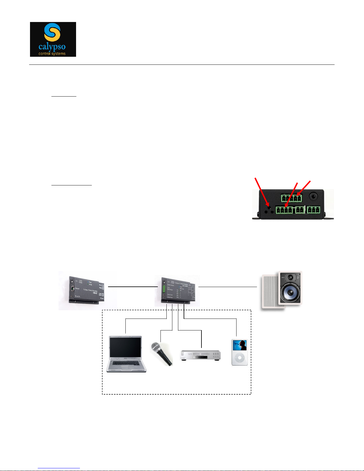
1.2.8 IR In
put
IR signals can be transmitted to the unit in two ways:
(a) The 3 triangular holes on the right side of the case allow for over-the-air IR
reception, good for line-of-sight t
ransmission, up to approximately 30 feet.
(b) IR signals may also be sent to the unit via hardwire, using the middle two pins on the
4-
pin connector located on the right side of the unit, labeled IR-
/GND and IR1+ IN.
Note that pin 3 is a shared ground conne
ctor.
1.2.9 Headphones
Headphones may be plugged into the unit using the 1/8 inch
mini jack located on the right
side. Note that the headphone
output
remains active even whe
n the
amplifier output is
muted on the CA-500 and CA-1000.
IR Window
IR Input Pins
Speaker Pins
Controller
CA-1000
IR or
Serial
Output
PC Audio
DVD Audio
Audio Inputs
Controller
CA-1000
IR or
Serial
Output
PC Audio
DVD Audio
Audio Inputs

Page
7
1.3 Using CA-Config Software
Once the unit is wired and powered up, CA Series configuration is managed entirely by CAConfig software, which is provided on a CD with the unit. CA-Config software must be install
ed
on the PC connected to the CA-1000 unit via the serial programming cable.
After
launch
ing the
software, select the
appropriate
serial port from the pull-
down;
it
should
automatically
initiate
communications
with the CA unit2. Note that reselecting the serial port from the drop-
down
menu re-initializes the application.
CA
-Config is a single-screen interface that provides all
settings and options with simple
push
buttons and pull-down menus.
2
Refer to section 1.1 for instructions on manually putting the unit into Program Mode.
Page
8
1.3.1
Input Channel Settings
The CA-500 CA-Config interface will provide access to Channel 1 In only, whereas all
channels will be active for CA-1000 and CA-1050 products. For each active channel, the
column of push buttons provide the following functions:
Enable / Disable
turns the channel on or off
Stereo / Mono
set the channel to stereo o
r mono input
(c
hannels 1-3 only)
Gain + / Gain
Use this setting to normalize volume across multiple inputs
, with 32 steps.
Ignore PA
3
available as an input to channel 4 (mono) only, this feature detects activity
on a PA system
and automatically triggers an automat
ed mute on input channels 1, 2 and
3.
The PA Detect circuit is triggered when the corresponding input on channel 4 exceeds
the defined Threshold setting.
This button rotates between three states:
o
Ignore PA
do nothing
o
PA w/norm
upon PA detect, mute
channels 1,2 and 3
and amplify channel 4 input
as per most recent (current) channel 4 settings. Note that current amplifier
settings may include low volume (determined by channel 4 Gain and Master
Volume) and/or mute, either of which would compromise the effectiveness of the
PA announcement.
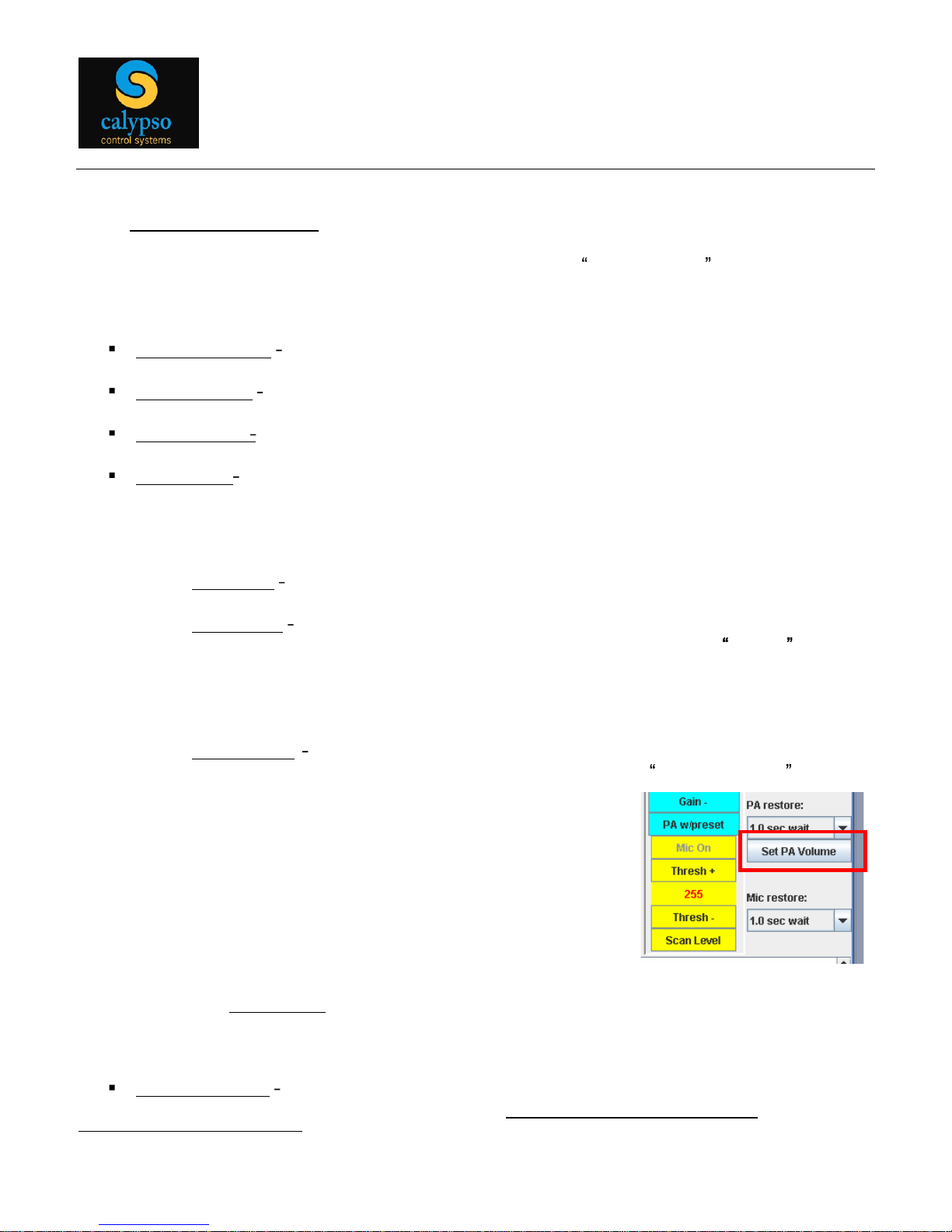
o PA w/preset
upon PA detect, mute channels 1,2 and 3 and amplify channel 4
input as per a preset channel 4 PA volume. Use the Set PA Volume button to
define the PA preset volume condition, as per
Master Out s
ettings
. Note that when using the PA
w/preset condition, channel 4 mute is automatically
turned off upon detection of a PA input.
In addition,
o
The
PA Restore
pull down defines the amount of time the amplifier waits between
the end of an active PA sig
nal and un-muting other channels
Mic Off / Mic On
use to define whether a microphone is connected
as the input device
to
the channel.
Note that t
he system allows for
only a single microphone input
.
3
Microphone detect and PA detect are mutually exclusive channel 4 conditions

Page
9
In multi-channel audio applications, microphones are often treated as a special input
device, capable of triggering automated ducking , where the volume of other inputs
automatically drop to preset levels, allowing microphone audio to be the dominant
source.
Accordingly, when a Mic On button is selected the Level setting for the active
microphone channel is changed to a Threshold setting, which is the microphone gain
threshold at which automated ducking of other channels initiates. Note that the
microphone threshold setting can be set manually, using the Thresh+ and Threshbuttons, or automatically, using the Scan Level button for the appropriate (i.e.,
microphone) channel.
Note: While monitoring for microphone input levels (typically, but not necessarily on
channel 4), the system searches only the LEFT side. Hence single channel
microphone
s
must be connected to the LEFT side input or plugged into a input set to operate in mono
mode.
After defining the ducking threshold level, one must also set the
setback
level of the other
audi
o inputs, using the existing, yellow
Setback
+ and
Setback buttons.
Finally, the Mic restore pull down defines the amount of time the amplifier waits between
the end of an active microphone signal and resetting the other channels to their normal
volum
e levels.
1.3.2 Master Out
Note: The amp waits 2 seconds after power on until output is enabled.
The settings on the Master Out menu bar determine audio output from the
CA
device.
1.
Channel Pull Down
use the pull down to switch between available
input
channels.
Change from Level to
Thresh
when Mic On
Define ducking levels for
non-microphone inputs

Page
10
2.
Set Start Ch
assign the current channel as the default channel used upon system start
up.
3. Vol + / Vol
-
increase and decrease output volume through 32 steps.
4.
Set Start Vol
assign the current volume setting as the default volume used upon system
start up. Warning: This allows full power start.
5. Mute Off -
toggle mute on and off
6. Bal R > / Bal L <
- balance left and right outputs through 16 steps (8 on each side).
1.3.3 Other Settings
CA
-Config includes a
number of additional
variable se
ttings.
1.
Both Codes
toggle button
selects
whether the
unit is scanning for CIRT1 IR codes, CIRT2 IR codes, or Both CIRT1 and CIRT2 codes.
A complete description of CIRT codes is provided in section 2.0 of
this
manual, which
covers IR control.
2.
IR Trg: 1
st
code
toggle the IR receiver to process the 1st, 2
nd
or 3
rd
IR code, transmitted
from a single IR remote control burst .
3.
IR Help
shows CIRT1 and CIRT2 IR codes (hex) and their corresponding CA
commands.
4. POT Settings
assists with remote diagnostics
and troubleshooting
5. Serial Port
define serial port communications settings
6.
Tone Off
toggle to turn a
900Hz
test tone on and off. The goal is to provide an output
signal
for testing speaker connections.
7.
CIRT 2 Settings
assign a specific 4-
char
CIRT (Calypso IR Trigger) code to specific CA
Series functions. Use the pulldown menu to select a specific function, type in a 4-
char
CIRT code and click the Assign button to associate the function with the code. Refer to
section 2.1 of this manual for d
etailed information on CIRT codes.

Page
11
8. AMP gain
use to
limit
maximum power output
.
2.0 IR and Serial Control
The CA Series of products are designed to be controlled by external devices that are capable of
transmitting IR or serial commands. For example, one could steer IR commands from a Calypso
CW
-1000 button panel to a CA-1000 IR input, and use the buttons to control
audio
channel
selection and volume. Similarly, a Pro I/O or ION controller could transmit IR or serial
commands to a CA-500, CA-
1000
or CA-1050 to provide PC-
based
amplifier
or pre-
amp
control
from PowerPoint, desktop icons or from other graphical interf
aces.
These tools make it
relatively easy to integrate audio control into a
full
range of AV presentation applications.
2.1 IR Command
Protocol
CA Series devices support
librar
ies
of IR codes known as CIRT (Calypso IR Trigger) codes
.
There are two distinct sets of CIRT codes, known as CIRT1 and CIRT2, both of which are
derived directly from standard, Sony 12-bit CD player IR commands (model CDP-
C715)
and re-
encoded as 2-byte hex strings for processing efficiency. All Calypso controllers with on-
board
IR learning have the ability to automatically convert the actual 12-bit Sony code into the
corresponding CIRT code.
CIRT1 codes are fixed , in that each code is pre-mapped to a specific CA Series function.
CIRT2 codes are
variable
, in that an integrator may define a valid
CIRT
code and then map it
to any CA Series function.
To implement IR control, an external device (e.g., Calypso CW-1000, Pro ION, ION contr
ollers
)
must
transmit CIRT codes to the CA unit, either through the air to the IR receive window, or
wired directly
through
the IR input terminal block. As a matter of convenience, CA products are
designed to boost the power of incoming CIRT commands, and re-transmit commands out to
another device. See section 1.2.9 for wiring details.
2.1.1 CIRT1 Codes - Fixed
Each CIRT1 code, shown in the table below, is mapped to a specific CA Series function.
Accordingly, the controlling device may be a Calypso ION, Pro I/O, UT-500 controller or any
other controller or IR transmitter that can be configu
red to send valid CIRT1 codes.

Page
12
CIRT1
(hex)
Function
Corresponding Sony
CDP-C715 Button
0880
Switch to input 1
Button 1
0881
Switch to input
2 (CA-1000, CA-1050 only) Button 2
0882
Switch to input 3 (CA-1000, CA-1050 only) Button 3
0883
Switch to input 4 (CA-1000, CA-1050 only) Button 4
08B1
Next channel
Next track
08B0
Previous channel
Prev track
0892
Vol Up (-2db step)
Master Vol Up
089
3
Vol Down (-2db step)
Master Vol Down
08B4
Vol Up (-4db step)
Shuttle FF
08B3
Vol Down (-4db step)
Shuttle Rev
08B2
Toggle mute
CD Play
08B9
Mute off
CD Pause
08B8
Mute on
CD Stop
2.1.2 CIRT2
Codes
User Defined
When necessary, you may configure the CA device to respond to ANY valid CIRT code, which
amounts to creating your own CIRT2 library. For example, the Calypso CB-1000 wall mount
button panel
contains the following
built-in CIRT code
s.
CB-1000 CIRT1
Codes
CB-1000 CIRT2 Codes
Button 1 = 01E
1
Button 1 = 02D1
Button 2 = 01E
2
Button 2 = 02D2
Button 3 = 01E
3
Button 3 = 02D3
Button 4 = 01E
4
Button 4 = 02D4
Button 5 = 01E
5
Button 5 = 02D5
Button 6 = 01E
6
Button 6 = 02D6
Button 7 = 01E7
Button 7 = 02D7
Button 8 = 01E8
Button 8 = 02D8
By mapping the CB-1000 CIRT codes to CA functions, the CB-1000 button panel can be
configured to control volume, channel, mute and other audio functions. CIRT code mapping
is
done using the CIRT 2 Settings pull down menu.

Page
13
2.2 Serial Command Protocol
The CA Series of products supports a fixed library of Serial commands, which
can
be
transmitted directly to the RS-
232
port
on the unit, which is also for CA-Config communications.
Note that each command mus
t end with a carriage return (
HEX = 0D).
Comm
and
Description
#ACHx
Select Audio Channel
x
1 =
Channel 1
2 = Channel 2
3 = Channel 3
4 = Channel 4
Command
Description
#ACH?
Return current channel selection
Command
Description
#ACF
Forward to next available channel
Command
Description
#ACR
R
everse to available channel
Command
Description
#AVIs
Increase volume, range 1-32 (-2db/step), steps 1
-3
s
1 = 1 step
2 = 2 steps
3 = 3 steps
Command
Description
#AVI
Increase volume 1 step, range 1-32 (-2db/step)
Command
Description
#AVDs
Decrea
se volume, range 1-32 (-2db/step), steps 1
-3
s
1 = 1 step
2 = 2 steps
3 = 3 steps
Command
Description
#AVD
Decrease volume 1 step, range 1-32 (-2db/step)

Page
14
Command
Description
#AVAv
Absolute volume setting, range 1-
32 (-2db)
v
1 thru 32
Command
D
escription
#AVA
?
Return current volume setting
Command
Description
#AVMx
Mute and un-mute output
x
0 = mute
1 = un-mute
Command
Description
#AVM
Toggle mute state
Command
Description
#AVM?
Return current mute setting

Page
15
3.0
Technical
Specifications
Audio Inputs
CA-500 Connectors/Channels
(1) 5-pin 3.81 Terminal Block
Header
(CH1)
balanced/unbalanced Stereo
CA-1000 / CA-1050 Connectors/Channels (1) 5-pin 3.81 Terminal Block
Header
(CH1)
balanced/unbalanced
Stereo
(2) 3.5mm Stereo Jack TRS (CH2 & CH3)
unbalanced Stereo
(1) 2-pin 3.81 Terminal Block
Header
(CH4)
balanced/unbalanced Mono
Impedance
>13k ohms unbalanced, >20k ohms
balanced
Nominal levels
+4 dBu (1.23 Vrms) balanced or -10 dBV
(316 mVrms)
unbalanced
Maximum level
+11dBu (2.75 Vrms) balanced or 2.9 dBV
(1.4 Vrms) unbalanced
Input level sensitivity for
maximum output
Amp Gain Setting 36db (max)
-
26 dBV (50mVrms) balanced / -32 dBV
(25mVrms) unbalanced
Amp Gain Setting 20db (min)
-9
dBV (350mVrms) balanced / -15 dBV
(175mVrms) unbalanced
Audio Output (Speakers)
Number / Signal type
1 stereo or 2 mono ( 2 channels total)
Connectors
5-
pin 3.81mm
screw down term block
Minimum load impedance
4 ohms
min
Amplifier type
Improved 9
2% Efficient Class D
Continuous power @ 1% THD
16
watts (rms) per channel @ 4 ohms, 8
watts (rms) per channel @ 8 ohms
Damping factor
>50 up to rated power with 4 ohm load
Frequency response
+/-1 dB, 20 Hz to 20 kHz, 1 watt output
THD + Noise
0.1% @ 1
kHz, at nominal level (1 watt, 8
ohm load)
S/N
>84
dB @ 20 Hz to 20 kHz at maximum
output
(unweighted, with balanced input)
Stereo channel separation
>65 dB @ 1 kHz, >58 dB @ 20 kHz
CMRR
>80 dB
Protection Circuits
Thermal and Short Circuit protected (Yellow
fault LED)
Output Limiter
4 settable gain levels (
20db, 26db, 32db,
36db
)
Headphone Outputs
Connector
3.5mm Stereo Jack TRS
Max output
-
2.0 dBV (0.8Vrms) into 32 Ohms
Frequency response
+/-1 dB, 20 Hz to 20 kHz,
THD + Noise
0.025% @ 1 kHz,
at maximum volume
Signal to noise ratio
>85 dB @ 20 Hz to 20 kHz at maximum
output
(unweighted, with balanced input)
Crosstalk
>65dB, 1kHz, channel-to-channel
Output impedance
75 Ohms
Working headphone impedance
32 to 600 Ohms
Audio Outputs
(Lin
e Out)
Connector
5-
pin 3.81mm Terminal Block Header
Max output (unbalanced)
+2.0 dBV (1.26Vrms)
Frequency response
+/-1 dB, 20 Hz to 20 kHz,
THD + Noise
0.025% @ 1 kHz, at maximum volume
Signal to noise ratio
>84
dB @ 20 Hz to 20 kHz at maximum ou
tput
(unweighted, with balanced input)
Crosstalk
>65dB, 1kHz, channel-to-channel
Output impedance
150 Ohms
Remote Control
Control port
RS232, 3-pin 3.81mm
screw down t
erminal
block
h
eader
IR remote
input
& IR wired, IR Repeater out
put
General
External Universal
Power Supply
100-240 VAC, 50/60 Hz, 1.5A;
12 VDC, 3.3A (nominal), regulated
Power input
requirements
12VDC
15VDC max, up to 3.5A
Power Output
12VDC
15VDC max, up to 0.5A (Active fuse)
Temperature/humidity Storage: -40 to
158 °F (-40 to +70 °C) / 10 - 90%,
non condensing
Operating: -32 to 122 °F (0 to +50 °C) / 10 - 90%,
non condensing
Enclosure type
Metal (Al), baked powdered black
Enclosure dimensions
1.2 H x 3.25 W x 5.1 D
3.1 cm H x 8.3 cm W x 13.0 cm D
Produc
t weight
0.5 lbs (0.2 kg)
Shipping weight
3 lbs (2 kg)
Warranty
3 years

Page
16
4.0
Warranty
CA-500/CA-1000/CA-1050 3-
Year Warranty
Calypso Control Systems 3-year Product Warranty Statement
This Non-Transferable warranty is provided to original purchasing end user, herein referred as
customer , of Calypso Control Systems product line defined as: Pro I/O, ION-e, ION-LT1, ION-
LT2, UT-500, ION-4s, ION-8r, ION-16i, CB-1000, CR-1200R, CA-500, CA-1000, and CA-
1050,
herein referred as product .
This warranty is applicable to product sold or distributed to customer by an authorized Calypso
Control Systems Dealer, OEM, Value Added Reseller or sold directly to the end user by Calypso
Control Systems, LLC. This warranty becomes effective from the moment the end user
completes purchase and receives product. This warranty shall remain in effect for 3 years from
the moment of purchase as long as the original customer of the product continues to own and
use the product. This warranty does not apply to accessories such as power supplies and
cables, which carry standard 12-month manufacturer warranties
.
Terms
Calypso Control Systems warrants that product shall be materially free of defects in material
and workmanship under normal use and service during the warranty period. In the event that
Calypso Control Systems receives notice from the customer during the warranty period that
product does not conform to this warranty, Calypso Control Systems shall, at its sole option,
either repair or replace the non-conforming product. The warranty on the replacement or
repaired product shall continue for the duration of the original warranty. All returned product
becomes the property of Calypso Control Systems.
Procedures
A product may only be returned with the prior written approval of Calypso Control Systems.
Such approval shall reference a Return Material Authorization number (RMA) issued by
authorized Calypso Control Systems technical support personnel. Transportation costs, if any,
incurred in connection with the return of a defective item to Calypso Control Systems shall be
borne by the Customer. Transportation costs incurred in connection with the re-delivery of a
repaired or replaced item to the Customer shall be borne by Calypso Control Systems.
However, such costs shall be borne by the Customer if Calypso Control Systems, reasonably
determines that the product is not defective. If Calypso Control Systems determines, in its sole
discretion, that the allegedly defective product is not covered by the terms of the warranty
provided hereunder, or that a warranty claim is made after the warranty period, the cost of repair
by Calypso Control Systems, including all shipping expenses, shall be reimbursed by the
Customer. Calypso Control Systems shall have no liability with respect to data contained in any

Page
17
system returned to Calypso
Control Systems.
Exclusions
The foregoing warranties and remedies are for the Customer s exclusive benefit and are non-
transferable. Any and all warranties shall be void regarding System components that are
damaged or rendered unserviceable by: (1) acts or omissions of non-Calypso Control Systems
personnel; (2) misuse, theft, vandalism, fire, water, or other peril; (3) alterations of or additions
to the System or any element thereof performed by personnel not certified by Calypso Control
Systems to perform such alterations and additions or (4) the Customer s failure to operate the
product in conformance with Calypso Control Systems published operating parameters,
including environmental specifications.
Disclaimer of Warranty
TO THE EXTENT ALLOWED BY APPLICABLE LAW, THE LIMITED WARRANTIES
REFERRED TO IN THE PARAGRAPHS ABOVE SHALL BE IN LIEU OF ALL OTHER
WARRANTIES WHETHER EXPRESSED, IMPLIED, STATUTORY, OR OTHERWISE.
CALYPSO CONTROL SYST
EMS,
LLC SPECIFICALLY DISCLAIMS ANY IMPLIED
WARRANTIES OF MERCHANTABI
LITY OR FITNESS FOR A PARTICULAR PURPOSE.
Limitation of Liability
TO THE EXTENT ALLOWED BY APPLICABLE LAW, CALYPSO CONTROL SYST
EMS
, LLC
AND ITS SUPPLIERS EXCLUDE THEMSELVES FROM ANY LIABILITY FOR ANY LOST
REVENUE OR PROFIT, LOSS OF BUSINESS, LOSS OF INFORMATION OR DATA, OR FOR
SPECIAL, INDIRECT, CONSEQUENTIAL, INCIDENTAL, OR PUNITIVE DAMAGES OF ANY
KIND CAUSED OUT OF OR IN CONNECTION WITH THE SALE, INSTALLATION,
MAINTENANCE, USE, PERFORMANCE, FAILURE, OR INTERRUPTION OF ITS PRODUCTS,
EVEN IF CALYPSO CONTROL SYSTEMS, LLC AND ITS AUTHORIZED RESELLERS HAVE
BEEN ADVISED OF THE POSSIBILITY OF SUCH DAMAGES. IN NO EVENT SHALL
CALYPSO CONTROL SYST
EMS
, LLC OR ITS SUPPLIERS TOTAL LIABILITY TO THE
CUSTOMER, WHETHER IN CONTRACT NEGLIGENCE, STRICT LIABILITY, TORT OR
OTHERWISE, EXCEED THE PRICE PAID BY THE CUSTOMER. THE FOREGOING
LIMITATIONS SHALL APPLY EVEN IF ANY REMEDY PROVIDED HEREIN SHALL FAIL ITS
ESSENTIAL PURPOSE. THIS LIMITATION OF LIABILITY, HOWEVER, WILL NOT APPLY TO
ANY CLAIMS FOR PERSONAL INJURY.
 Loading...