


GSA
Gas-Fired Steam Boilers
Boiler Manual
Contents Page
1 Prepare boiler location ........................................................ 2
2 Prepare boiler ..................................................................... 6
3 Install piping ........................................................................ 9
4 Install controls .................................................................. 11
5 Install gas piping ............................................................... 12
6 Field wiring ....................................................................... 13
7 Start-up ............................................................................ 14
8 Checkout procedure ......................................................... 16
9 Sequence of operation ...................................................... 17
10 Lighting instructions .......................................................... 18
11 Service and maintenance ................................................. 20
12 Troubleshooting ................................................................ 24
13 Replacement parts ........................................................... 26
14 Dimensions ...................................................................... 30
15 Ratings ............................................................................. 31
Hazard definitions
Hazards that will cause severe personal injury,
death or substantial property damage.
Hazards that can cause severe personal injury,
death or substantial property damage.
INSTALLER — Read all instructions before
installing. Read page 2 first. Follow all instructions
in proper order to prevent personal injury or death.
• Consider piping and installation when determining
boiler location.
• Any claims for damage or shortage in shipment
must be filed immediately against the transportation
company by the consignee.
• GSA boilers cannot be adapted for heater use.
This manual must only be used by a qualified heating installer/service technician. Failure to comply could result in
severe personal injury, death or substantial property damage.
When calling or writing about the boiler— Please have: • boiler model number from the boiler rating label and • CP number
from the boiler jacket. You may list the CP number in the space provided on the “Installation and service certificate” found on
page 16.
Hazards that will or can cause minor personal injury
or property damage.
Special instructions on installation, operation or
maintenance that are important but not related to
personal injury or property damage.
USER — Please read the following. Failure to
comply could result in severe personal injury, death
or substantial property damage.
• This manual is for use only by your qualified
heating installer/service technician.
• Please see the User’s Information Manual for your
reference.
• Have the boiler serviced by a qualified service
technician, at least annually.
Part Number 550-110-738/0703

GSA
Gas-Fired Steam Boilers – Boiler Manual
1 Prepare boiler locationRead this first!
Failure to adhere to the guidelines below can
result in severe personal injury, death or
substantial property damage.
The boiler contains ceramic fiber and
fiberglass materials. Use care when handling
these materials per instructions on page 32
of this manual. Failure to comply could result
in severe personal injury.
When servicing boiler —
1. To avoid electric shock, disconnect electrical supply
before performing maintenance.
2. To avoid severe burns, allow boiler to cool before
performing maintenance.
Boiler operation —
3. Do not block flow of combustion or ventilation air to boiler.
4. Should overheating occur, turn off or disconnect electrical
supply to boiler and shut off the gas supply at a location
external to the appliance, if possible.
5. Do not use this boiler if any part has been under water.
Immediately call a qualified service technician to inspect
the boiler and to replace any part of the control system
and any gas control that has been under water.
Boiler water —
6. DO NOT use petroleum-based cleaning or sealing
compounds in boiler system. Water seal deterioration will
occur, causing leakage between boiler sections, circulator
flanges, diaphragm tanks or other system components.
This can result in substantial property damage.
7. DO NOT use "homemade cures" or "boiler patent
medicines". Serious damage to boiler, personnel and/or
property may result.
8. Continual fresh makeup water will reduce boiler life. Mineral
buildup in sections reduces heat transfer, overheats cast
iron, and causes section failure. Addition of oxygen and
other gases can cause internal corrosion. Leaks in boiler
or piping must be repaired at once to prevent makeup
water.
9. Do not add cold water to hot boiler. Thermal shock can
cause sections to crack.
Codes & checklist
Installations must follow these codes:
• Local, state, provincial, and national codes, laws, regulations
and ordinances.
• National Fuel Gas Code, ANSI Z223.1–latest edition.
• Standard for Controls and Safety Devices for Automatically
Fired Boilers, ANSI/ASME CSD-1, when required.
• National Electrical Code.
• For Canada only: B149.1 or B149.2 Installation Code, CSA
C22.1 Canadian Electrical Code Part 1 and any local codes.
Certification
The GSA boiler gas manifold and controls met safe
lighting and other performance criteria when boiler
underwent tests specified in ANSI Z21.13–latest
edition.
Before locating the boiler:
❏ Check for nearby connection to:
• Venting connections
• Gas supply piping
• Electrical power
❏ Check area around boiler. Remove any combustible materials,
gasoline and other flammable liquids.
Failure to keep boiler area clear and free of
combustible materials, gasoline and other flammable
liquids and vapors can result in severe personal
injury, death or substantial property damage.
❏ Boiler must be installed so that gas control system components
are protected from dripping or spraying water or rain during
operation or service.
❏ If new boiler will replace existing boiler, check for and correct
system problems, such as:
1. System leaks causing oxygen corrosion or section cracks
from hard water deposits.
2 Part Number 550-110-738/0703

GSA
1 Prepare boiler location continued
Clearances
Gas-Fired Steam Boilers – Boiler Manual
Service clearances
1. Provide minimum clearances for cleaning and servicing the
boiler and for access to controls and components as listed in
the table below.
2. Provide at least screwdriver clearance to jacket front panel
screws for removal of front panel for inspection and minor
service. If unable to provide at least screwdriver clearance,
install unions and shutoff valves in system so boiler can be
moved for servicing.
Service clearances: Minimum
Top
(for cleaning flueways)
Front
(for access to controls and components)
46"
18"
Back 6"
Left side
(for cleaning and servicing)
24"
Right side 6"
Minimum clearance to combustible materials
General — all installations
1. Hot water pipes must be at least ½" from combustible material.
2. Single-wall vent pipe must be at least 6 inches from combustible
material.
3. Type B double-wall metal vent pipe — See vent manufacturer’s
recommendation for clearances to combustible material.
Small space — alcove (not closet) installation
GSA boilers are not approved for closet installation
— only for alcove installation, with minimum
clearances as shown in Figure 1 and the table below,
and the front side completely open — that is, a 3walled room.
Clearances from combustible materials: Minimum
Top 46"
Front
(provide means of access)
Back 6"
Left side
(provide means of access)
Right side 4"
Large space — (see minimum room volume, below)
If installed in a four-walled room, the room volume must be no less
than the following (Ceiling height, if over 8 feet, can only be counted
as 8 feet.):
GSA-075 & GSA-100 147 cubic feet
GSA-125 & GSA-150 184 cubic feet
GSA-175 & GSA-200 221 cubic feet
GSA-250 257 cubic feet
The room must provide the following minimum clearances (in all
directions) to the boiler and components:
Jacket and flue collector sides & rear 6 inches
Jacket front 18 inches
Vent pipe (other than Type B vent) 6 inches
Vent damper 6 inches
3"
4"
Figure 1 Minimum clearances - alcove installation only
Residential garage installation
Take the following special precautions when installing the boiler in
a residential garage. If the boiler is located in a residential garage,
per ANSI Z223.1, paragraph 5.1.9:
• Mount the boiler a minimum of 18 inches above the floor of the
garage to assure the burner and ignition devices will be no less
than 18 inches above the floor.
• Locate or protect the boiler so it cannot be damaged by a moving
vehicle.
Flooring and foundation
Do not install boiler on combustible flooring or
carpeting even if a concrete or aerated foundation is
used. Fire can result, causing severe personal injury,
death or substantial property damage.
1. Provide a solid brick or minimum 2-inch thick concrete
foundation pad if any of the following is true:
• floor can become flooded.
• the boiler mounting area is not level.
2. See Table 1 for minimum foundation dimensions.
3. Use a foundation with airways when:
• Electrical wiring or telephone cables buried in the concrete
floor of the boiler room.
• Concrete floor is “green”.
• Water is channeled under the concrete.
Table 1 Minimum foundation size
Boiler
model
GSA-075 — GSA-100
GSA-125 — GSA-150
GSA-175 — GSA-200
GSA-250
Minimum
foundation
length
5
29
/
8
"
5
29
/
8
" 23
5
29
/
8
" 27
5
29
/
8
" 31
Minimum
foundation
width
19"
1
/
4
1
/
2
3
/
4
"
"
"
3Part Number 550-110-738/0703

GSA
Gas-Fired Steam Boilers – Boiler Manual
1 Prepare boiler location continued
Vent system
Failure to follow all instructions can result in flue gas
spillage and carbon monoxide emissions, causing
severe personal injury or death.
Inspect existing chimney before installing boiler.
Failure to clean or replace perforated pipe or tile lining
will cause severe personal injury or death.
Do not alter boiler draft diverter or place any
obstruction or non-certified vent damper in breeching
or vent system. CSA certification will become void.
Flue gas spillage and carbon monoxide emissions
will occur causing severe personal injury or death.
The following requirements apply when you remove
an existing boiler from a vent system shared with
other appliances. If the new boiler will not use the
common vent, you must test (as described below)
each remaining appliance — operating by itself — to
verify that the vent system operates adequately.
When removing boiler from existing common vent
system:
At the time of removal of an existing boiler, the following steps shall
be followed with each appliance remaining connected to the common
venting system placed in operation, while the other appliances
remaining connected to the common venting system are not in
operation.
a. Seal any unused openings in the common venting system.
b. Visually inspect the venting system for proper size and horizontal
pitch and determine there is no blockage or restriction, leakage,
corrosion or other deficiencies which could cause an unsafe
condition.
c. Test vent system — Insofar as is practical, close all building
doors and windows and all doors between the space in which
the appliances remaining connected to the common venting
system are located and other spaces of the building. Turn on
clothes dryers and any appliance not connected to the common
venting system. Turn on any exhaust fans, such as range hoods
and bathroom exhausts, so they will operate at maximum speed.
Do not operate a summer exhaust fan. Close fireplace dampers.
d. Place in operation the appliance being inspected. Follow the
lighting instructions. Adjust thermostat so appliance will operate
continuously.
e. Test for spillage at draft diverter relief opening after 5 minutes
of main burner operation. Use the flame of a match or candle.
f. After it has been determined that each appliance remaining
connected to the common venting system properly vents when
tested as outlined above, return doors, windows, exhaust fans,
fireplace dampers, and any other gas-burning appliance to their
previous conditions of use.
Any improper operation of common venting system should be
corrected so the installation conforms with the National Fuel Gas
Code, ANSI Z223.1–latest edition. Correct by resizing to approach
the minimum size as determined using the appropriate tables in
Part 11 of that code. Canadian installations must comply with B149.1
or B149.2 Installation Code.
Equipment”, of National Fuel Gas Code, ANSI Z223.1–latest
edition and applicable building codes. Canadian installations
must comply with B149.1 or B149.2 Installation Codes.
2. See “Ratings” on page 31 for minimum chimney or vent sizes.
Chimney or vent termination:
• A chimney, or any vent other than a Type B vent with listed
vent cap, must extend at least 3 feet above the highest point
where it passes through a roof of a building, and at least
2 feet higher than any portion of a building within a horizontal
distance of 10 feet.
• Type B vents with listed caps may terminate as in Figure 2
if no closer than 8 feet from a vertical wall or similar
obstruction.
• Otherwise, Type B vents must terminate at least 2 feet above
the roof penetration and at least 2 feet higher than any portion
of a building within 10 feet.
3. A lined chimney is preferred and must be used when required
by local, state, provincial and national codes, laws, regulations
and ordinances. Vitreous tile linings with joints that prevent
retention of moisture and linings made of noncorrosive materials
are best. Advice for flue connections and chimney linings can
be obtained from local gas utility. Type B double-wall metal vent
pipe or single-wall vent pipe may be used as a liner.
4. Cold masonry chimneys, also known as outside chimneys,
typically have one or more walls exposed to outside air.
When any atmospheric gas-fired boiler with automatic vent
damper is vented through this type of chimney, the potential
exists for condensation to occur. Condensation can damage a
masonry chimney. The following are recommended to prevent
possible damage.
a. Line chimney with corrosion-resistant metal liner such as
AL29-4C® single-wall stainless steel or B-vent. Size liner
per National Fuel Gas Code ANSI Z223.1–latest edition.
b. Provide drain trap to remove any condensate.
5. Where two or more gas appliances vent into a common
chimney or vent, equivalent area should be at least equal to
area of vent outlet on largest appliance plus 50 percent of vent
outlet area of additional appliances.
Figure 2 Terminations with Type B vent fitted with
listed cap, provided vent is at least 8 feet
from any vertical wall or similar obstruction
Chimney or vent requirements
1. Venting must be installed according to Part 7, “Venting of
4 Part Number 550-110-738/0703

GSA
Gas-Fired Steam Boilers – Boiler Manual
1 Prepare boiler location continued
Air contamination Air openings
Please review the following information on potential combustion air
contamination problems.
See Table 2 for products and areas which may cause contaminated
combustion air.
To prevent potential of severe personal injury or death,
check for products or areas listed below before
installing boiler. If any of these contaminants are found:
• Remove contaminants permanently.
— OR —
• Isolate boiler and provide outside combustion air. See
national, provincial or local codes for further
information.
Table 2 Corrosive contaminants and likely locations
Products to avoid
Spray cans containing chloro/fluorocarbons
Permanent wave solutions
Chlorinated waxes/cleaners
Chlorine-based swimming pool chemicals
Calcium chloride used for thawing
Sodium chloride used for water softening
Refrigerant leaks
Paint or varnish removers
Hydrochloric acid/muriatic acid
Cements and glues
Antistatic fabric softeners used in clothes dryers
Chlorine-type bleaches, detergents, and cleaning solvents found in
household laundry rooms
Adhesives used to fasten building products and other similar products
Combustion air and ventilation openings must comply with Section
5.3, “Air for Combustion and Ventilation”, of National Fuel Gas Code
ANSI Z223.1–latest edition, or applicable local building codes.
Canadian installations must comply with B149.1 or B149.2
Installation Codes.
See table below for minimum combustion/ventilation air opening
sizes. Where openings are required, provide two (2) openings —
one within 12 inches of the ceiling, the other within 12 inches of the
floor, as shown in the table illustrations.
Provide adequate combustion and ventilation air to
assure proper combustion and reduce the risk of
severe personal injury, death or substantial property
damage caused by flue gas spillage and carbon
monoxide emissions.
Areas likely to have contaminants
Dry cleaning/laundry areas and establishments
Swimming pools
Metal fabrication plants
Beauty shops
Refrigeration repair shops
Photo processing plants
Auto body shops
Plastic manufacturing plants
Furniture refinishing areas and establishments
New building construction
Remodeling areas
Garages with workshops
5Part Number 550-110-738/0703

GSA
Gas-Fired Steam Boilers – Boiler Manual
1 Prepare boiler location continued
Air openings continued
Exhaust fans and air movers
The appliance space must never be under a negative pressure.
Always provide air openings sized not only to the dimensions
required for the firing rate of all appliances, but also to handle the air
movement rate of the exhaust fans or air movers using air from the
building or space.
2 Prepare boiler
Placement and setup
Place boiler/crate near position
1. Leave boiler in crate and on pallet until installation site is
ready.
2. Move entire crate and pallet next to selected location.
3. Remove crate. Leave boiler on pallet.
4. Unbolt boiler from pallet.
5. Remove boiler from pallet.
Motorized air dampers
If the air openings are fitted with motorized dampers, electrically
interlock the damper to:
• Prevent the boiler from firing if the damper is not fully open.
• Shut the boiler down should the damper close during boiler
operation.
To accomplish this interlock, wire an
damper open) in series with the thermostat input to the boiler. The
boiler will not start if this damper is closed, and will shut down should
damper close during operation.
Table 3 Manifold orifice sizing
isolated contact
(proving the
Inspect orifices and burners
1. Remove front jacket door. Remove base access panel (see
Figure 16, item 14, page 26).
2. Check for correctly-sized manifold orifices. See Table 3 for sizing.
(The orifice size is stamped on the orifice spud barrel.)
Correctly-sized manifold orifices must be used. Failure
to do so will result in severe personal injury, death or
substantial property damage.
3. Level and straighten burners.
Burners must be properly seated in slots in burner
rest with their openings face up. Main burner orifices
must inject down center of burner. Failure to properly
seat burners will result in severe personal injury,
death or substantial property damage.
4. Reinstall base access panel.
Do not operate boiler without access panel secured
in place. Failure to comply could cause momentary
flame rollout on ignition of main flame, resulting in
possible fire or personal injury hazard.
Pressure test
Perform hydrostatic pressure test
Pressure test boiler before attaching water or gas piping or electrical
supply.
Prepare boiler for test
1. Plug tappings or openings.
2. Do not use gauge supplied with boiler for pressure testing. Install
gauge with appropriate range.
Fill and pressure test
1. Fill boiler with water. Vent all air. Test boilers between 45-50 psi.
Do not leave boiler unattended. A cold water fill could
expand and cause excessive pressure resulting in
severe personal injury, death or substantial property
damage.
2. Check for maintained gauge pressure for more than 10 minutes.
Visually check for leaks if gauge pressure drops.
6 Part Number 550-110-738/0703
GSA
Gas-Fired Steam Boilers – Boiler Manual
2 Prepare boiler continued
Pressure test continued Draft diverter & spill switch
Drain and remove fittings
1. Drain boiler and repair leaks if found.
Leaks must be repaired at once. Failure to do so can
damage boiler, resulting in substantial property
damage.
Do not use petroleum based cleaning or sealing
compounds in boiler system. Severe damage to boiler
will result, causing substantial property damage.
2. Retest boiler after repairing leaks.
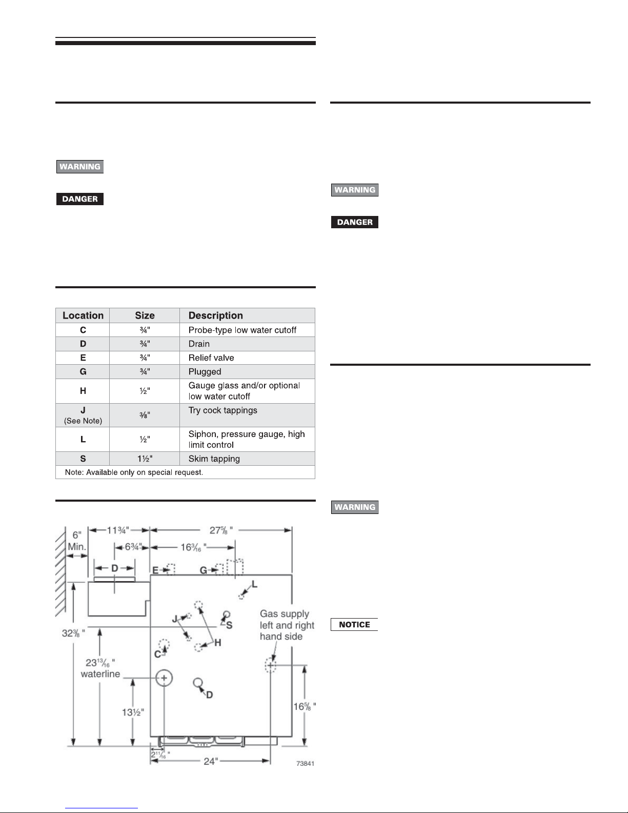
3. Remove plugs from any tappings that will be used for controls
and accessories. Refer to Table 4 and Figure 3, below.
Table 4 Control tapping
Figure 3 Control tapping locations
Draft diverter installation
1. Secure draft diverter to flue collector hood with sheet metal
screws. See Figure 16, items 1 and 9, on page 26. Use boiler
cement to provide gas tight seal.
Failure to maintain gas-tight seal can cause flue gas
spillage and carbon monoxide emissions, resulting
in severe personal injury or death.
Do not alter boiler draft diverter or place any
obstruction or non-approved vent damper in
breeching or vent system. CSA certification will
become void. Flue gas spillage and carbon monoxide
emissions will occur causing severe personal injury
or death.
Spill switch installation
1. Fasten spill switch to draft diverter as shown in Figure 16, item
20, page 26.
2. See Wiring diagram on page 17 to connect wires.
Install vent piping
1. Connect from draft diverter or vent damper outlet to chimney or
vent with same size vent connector.
2. Where possible, vertical venting to the outside from the draft
diverter or vent damper outlet will offer best performance.
3. Where horizontal vent connector is used, slope upward at least
¼" per lineal foot toward chimney or vent and support with
hangers to prevent sagging.
4. Breeching must not be connected to any portion of a mechanical
draft system that can operate under positive pressure.
Long horizontal vent connector, excessive number
of elbow or tees, or other obstructions that restrict
the flow of combustion gases should be avoided.
Severe personal injury, death or substantial property
damage could result.
Float-type low water cutoff — If field installing a floattype low water cutoff, it must be piped only to the
gauge glass tappings, items H, Figure 3. The tappings
are spaced 9" on center. Use only float-type low water
cutoffs with quick-connect hookups that will provide
a low water cutoff point no higher than 2" above the
center of the bottom tapping. See page 11, Figure 9,
for a typical installation.
7Part Number 550-110-738/0703

GSA
Gas-Fired Steam Boilers – Boiler Manual
2 Prepare boiler continued
Vent damper
These systems are used on gas-fired boilers with
vent dampers as shipped from factory. Boiler will not
operate without vent damper installed.
Damper blade
See vent manufacturer’s instructions to install plug (shipped with
damper) in damper hole. Install plug with
damper hole.
Minimum clearances
Provide a minimum of 6" between the vent damper and any
combustible material. (See “Minimum clearance to combustible
materials,” page 3, for minimum clearance from jacket top to ceiling
to maintain this dimension.)
Damper installation
Do not modify draft diverter or vent damper, or make
another connection between draft diverter and vent
damper or boiler except as noted below. This will void
CSA certification and will not be covered by warranty.
Any changes will cause severe personal injury, death
or substantial property damage.
1. Install vent damper as shown in vent damper manufacturer’s
instructions. Vent damper must be installed so that it serves
only one boiler and so damper blade indicator is visible to the
user. See Figure 4.
2. Screws or rivets used to secure the vent damper to the draft
diverter must not interfere with rotation of the damper blade.
3. Install damper harness between damper actuator and knockout
in jacket top panel. Use strain relief connectors and locknuts to
secure both ends of damper harness.
Keep wiring harness clear of all hot surfaces. Wire
insulation could be damaged, causing risk of electrical
short-circuit.
3
/
8" diameter hole in vent
4. Read and apply the harness plug warning label (shown above)
so that it is visible after installation
5. Plug damper harness receptacle into damper harness plug.
Bypassing (jumpering) vent damper will cause flue
products such as carbon monoxide to escape into
the house. This will cause severe personal injury or
death.
After boiler has operated once, if either end of harness
is disconnected, the system safety shutdown will
occur. The boiler will not operate until harness is
reconnected.
Effikal damper — Damper hold open switch must be
in Automatic Operation position for system to operate
properly.
Figure 4 Vent damper assemblies
8 Part Number 550-110-738/0703

3 Install piping
GSA
Gas-Fired Steam Boilers – Boiler Manual
General
1. Pipe before installing controls. Connect return piping after jacket
is attached. Connect supply piping before or after jacket is
attached.
Failure to properly pipe the boiler may result in
improper operation and damage to the boiler or
building.
2. See Figure 5 and Table 5. Pipe exactly as shown. Satisfactory
operation of a steam heating system depends on adequate
condensate return to boiler to maintain a steady water level.
Avoid adding raw makeup water. Where condensate return is
not adequate, install low water cutoff/pump control, condensate
receiver and condensate boiler feed pump. Refer to Table 7,
page 10, for sizing. See page 7, Table 4, for tapping locations.
Figure 5 Recommended piping, piping for parallel-
flow systems only.
Connecting to counterflow piping
Apply the recommended piping in Figures 4 through 7 only when
connecting to a parallel-flow system. When connecting to a
counterflow system, the boiler steam supply must connect into the
top of the counterflow system header, as shown in Figure 6.
Figure 6 Connection to counterflow steam piping
Table 5 Recommended pipe sizing
Boiler model number Riser (A) Header (H)
GSA-075 and GSA-100 2" 2" 1½"
GSA-125 through GSA-175 2½" 2 ½" 1½"
GSA-200 and GSA-250 3" 3" 1½"
Note: 24" minimum from waterline to header.
see Note
Equalizer (J)
Relief valve
Install relief valve in tapping on top of boiler. See Table 4, page 7,
for control tapping locations. See the tag attached to the relief valve
for manufacturer’s instructions.
Follow the steps below to avoid potential severe
personal injury, death or substantial property damage.
• When installing the relief valve, ensure that all
connections, including the valve inlet, are clean and
free from any foreign matter.
• Mount the relief valve only in the vertical position,
directly connected to the tapping designated in the
manual on top of the boiler.
• Use pipe compound sparingly, or tape, on external
threads only.
• Do not use a pipe wrench! Use proper type and size
wrench on wrench pads only.
9Part Number 550-110-738/0703

GSA
Gas-Fired Steam Boilers – Boiler Manual
3 Install piping continued
Relief valve continued
During operation, this valve may discharge large
amounts of steam and/or hot water. Therefore, to
reduce the potential for bodily injury and property
damage, a discharge line MUST be installed that:
• Is connected from the outlet to a safe point of
discharge with no intervening valve.
• Allows complete drainage of both the valve and the
discharge line.
• Is independently supported and securely anchored
so as to avoid applied stress as possible.
• Terminates freely to atmosphere where any
discharge will be clearly visible and is at no risk of
freezing.
• Is, over its entire length, of a pipe size equal to or
greater than that of the valve outlet.
Use only schedule 40 metal pipe for discharge. (Do
not use schedule 80, extra strong or double strong
pipe or connections.) DO NOT CAP, PLUG OR
OTHERWISE OBSTRUCT DISCHARGE PIPE
OUTLET! If discharge is piped upward, a condensate
drain must be provided in the elbow below the vertical
pipe to prevent condensate from returning into the
valve. Failure to comply with these instructions will
cause a dangerous spray of hot water and steam
that would cause severe personal injury or death.
Table 6 Reservoir pipe sizing
Boiler
model
number
GSA-075 75
GSA-100 100
GSA-125 125
GSA-150 150
GSA-175 175 1¾
GSA-200 200 2
GSA-250 250 2½
Designed full capacity steaming time of modern boilers is 10 minutes.
Boiler
gross
output
MBH
Time from initial steaming to average condensate
return (boiler steaming capacity based on 970 Btu per
15 minutes 20 minutes 30 minutes
gallons
1
1
1¼
1½ 1½ 3 2½
pipe
length
(feet)
1
1
1¼
1¾
2
2¼
pound of steam)
gallons
pipe
length
(feet)
1½
1½
2
2½
2
2¼
Use boiler feed system
gallons
pipe
length
(feet)
Use boiler feed
system
Condensate return
Modern steam boilers are designed to steam for less time than
older, larger boilers. When replacing an older steam boiler the system
condensate return time may be longer than the steaming time. This
could cause the following problems:
1. Boilers fitted with an automatic water feed could overfill.
2. Units fitted with only a low water cutoff would shut down and
cycle while waiting for condensate to return.
Following is a simple method for determining whether or not a
reservoir pipe is required to lengthen steaming time for a residential
installation:
1. Disconnect condensate return line at existing boiler.
2. Heat boiler and allow to steam for 10 minutes. Turn off boiler.
3. Measure length of time from when boiler started to steam to
when condensate begins to return through condensate line.
4. Measure length of time from when condensate begins to return
to when it stops returning. Divide this time by 2.
5. Add time measured in step 3 to time calculated in step 4. This
sum is the average time required for condensate to return to
the boiler.
6. If this total time is 10 minutes or less, no reservoir pipe is needed.
If total time for condensate to return to boiler (from step 5) is more
than 10 minutes, a reservoir pipe (or boiler feed system) is
recommended. See Table 6, this page, for suggested reservoir pipe
size. Install as shown in Figure 7, below.
For larger systems (as noted in Table 6), use a boiler feed system
with a condensate tank and feed pump. You will have to install a low
water cutoff/pump control on the boiler to operate the pump. Use
Table 7 to size boiler feed systems. See page 7, Table 4, for tapping
locations. (The use of a combination condensate tank and floatcontrolled condensate return pump is not recommended.)
For most residential installations a reservoir pipe may be all that is
necessary to ensure proper operation.
Figure 7 Recommended piping for parallel-flow
systems with optional reservoir pipe
Table 7 Boiler feed system sizing
Boiler
model
number
GSA-075 63 8 2 4 6 8 0.2
GSA-100 81 10 3 6 9 12 0.3
GSA-125 102 12 4 7 11 14 0.4
GSA-150 122 15 5 9 14 18 0.5
GSA-175 142 17 5 10 15 20 0.6
GSA-200 163 20 6 12 18 24 0.7
GSA-250 203 24 7 14 22 29 0.8
Notes
1. Maximum time to when condensate returns to boiler.
2. If pump capacity exceeds capacity shown, pump can be throttled with globe or
ball valve.
I=B=R
gross
output
(pounds
steam
per hour)
Conden-
sate
(gallons
per hour)
Minimum condensate receiver
capacity gallons for boiler
steaming times (minutes) of:
15 min. 30 min. 45 min. 60 min.
(note 1)
10 Part Number 550-110-738/0703
Suggested
feed pump
capacity
(GPM @
15 PSI)
(note 2)
 Loading...