

Page 1

GSA
Gas-Fired Steam Boilers
Boiler Manual
Contents Page
1 Prepare boiler location ........................................................ 2
2 Prepare boiler ..................................................................... 6
3 Install piping ........................................................................ 9
4 Install controls .................................................................. 11
5 Install gas piping ............................................................... 12
6 Field wiring ....................................................................... 13
7 Start-up ............................................................................ 14
8 Checkout procedure ......................................................... 16
9 Sequence of operation ...................................................... 17
10 Lighting instructions .......................................................... 18
11 Service and maintenance ................................................. 20
12 Troubleshooting ................................................................ 24
13 Replacement parts ........................................................... 26
14 Dimensions ...................................................................... 30
15 Ratings ............................................................................. 31
Hazard definitions
Hazards that will cause severe personal injury,
death or substantial property damage.
Hazards that can cause severe personal injury,
death or substantial property damage.
INSTALLER — Read all instructions before
installing. Read page 2 first. Follow all instructions
in proper order to prevent personal injury or death.
• Consider piping and installation when determining
boiler location.
• Any claims for damage or shortage in shipment
must be filed immediately against the transportation
company by the consignee.
• GSA boilers cannot be adapted for heater use.
This manual must only be used by a qualified heating installer/service technician. Failure to comply could result in
severe personal injury, death or substantial property damage.
When calling or writing about the boiler— Please have: • boiler model number from the boiler rating label and • CP number
from the boiler jacket. You may list the CP number in the space provided on the “Installation and service certificate” found on
page 16.
Hazards that will or can cause minor personal injury
or property damage.
Special instructions on installation, operation or
maintenance that are important but not related to
personal injury or property damage.
USER — Please read the following. Failure to
comply could result in severe personal injury, death
or substantial property damage.
• This manual is for use only by your qualified
heating installer/service technician.
• Please see the User’s Information Manual for your
reference.
• Have the boiler serviced by a qualified service
technician, at least annually.
Part Number 550-110-738/0703
Page 2

GSA
Gas-Fired Steam Boilers – Boiler Manual
1 Prepare boiler locationRead this first!
Failure to adhere to the guidelines below can
result in severe personal injury, death or
substantial property damage.
The boiler contains ceramic fiber and
fiberglass materials. Use care when handling
these materials per instructions on page 32
of this manual. Failure to comply could result
in severe personal injury.
When servicing boiler —
1. To avoid electric shock, disconnect electrical supply
before performing maintenance.
2. To avoid severe burns, allow boiler to cool before
performing maintenance.
Boiler operation —
3. Do not block flow of combustion or ventilation air to boiler.
4. Should overheating occur, turn off or disconnect electrical
supply to boiler and shut off the gas supply at a location
external to the appliance, if possible.
5. Do not use this boiler if any part has been under water.
Immediately call a qualified service technician to inspect
the boiler and to replace any part of the control system
and any gas control that has been under water.
Boiler water —
6. DO NOT use petroleum-based cleaning or sealing
compounds in boiler system. Water seal deterioration will
occur, causing leakage between boiler sections, circulator
flanges, diaphragm tanks or other system components.
This can result in substantial property damage.
7. DO NOT use "homemade cures" or "boiler patent
medicines". Serious damage to boiler, personnel and/or
property may result.
8. Continual fresh makeup water will reduce boiler life. Mineral
buildup in sections reduces heat transfer, overheats cast
iron, and causes section failure. Addition of oxygen and
other gases can cause internal corrosion. Leaks in boiler
or piping must be repaired at once to prevent makeup
water.
9. Do not add cold water to hot boiler. Thermal shock can
cause sections to crack.
Codes & checklist
Installations must follow these codes:
• Local, state, provincial, and national codes, laws, regulations
and ordinances.
• National Fuel Gas Code, ANSI Z223.1–latest edition.
• Standard for Controls and Safety Devices for Automatically
Fired Boilers, ANSI/ASME CSD-1, when required.
• National Electrical Code.
• For Canada only: B149.1 or B149.2 Installation Code, CSA
C22.1 Canadian Electrical Code Part 1 and any local codes.
Certification
The GSA boiler gas manifold and controls met safe
lighting and other performance criteria when boiler
underwent tests specified in ANSI Z21.13–latest
edition.
Before locating the boiler:
❏ Check for nearby connection to:
• Venting connections
• Gas supply piping
• Electrical power
❏ Check area around boiler. Remove any combustible materials,
gasoline and other flammable liquids.
Failure to keep boiler area clear and free of
combustible materials, gasoline and other flammable
liquids and vapors can result in severe personal
injury, death or substantial property damage.
❏ Boiler must be installed so that gas control system components
are protected from dripping or spraying water or rain during
operation or service.
❏ If new boiler will replace existing boiler, check for and correct
system problems, such as:
1. System leaks causing oxygen corrosion or section cracks
from hard water deposits.
2 Part Number 550-110-738/0703
Page 3

GSA
1 Prepare boiler location continued
Clearances
Gas-Fired Steam Boilers – Boiler Manual
Service clearances
1. Provide minimum clearances for cleaning and servicing the
boiler and for access to controls and components as listed in
the table below.
2. Provide at least screwdriver clearance to jacket front panel
screws for removal of front panel for inspection and minor
service. If unable to provide at least screwdriver clearance,
install unions and shutoff valves in system so boiler can be
moved for servicing.
Service clearances: Minimum
Top
(for cleaning flueways)
Front
(for access to controls and components)
46"
18"
Back 6"
Left side
(for cleaning and servicing)
24"
Right side 6"
Minimum clearance to combustible materials
General — all installations
1. Hot water pipes must be at least ½" from combustible material.
2. Single-wall vent pipe must be at least 6 inches from combustible
material.
3. Type B double-wall metal vent pipe — See vent manufacturer’s
recommendation for clearances to combustible material.
Small space — alcove (not closet) installation
GSA boilers are not approved for closet installation
— only for alcove installation, with minimum
clearances as shown in Figure 1 and the table below,
and the front side completely open — that is, a 3walled room.
Clearances from combustible materials: Minimum
Top 46"
Front
(provide means of access)
Back 6"
Left side
(provide means of access)
Right side 4"
Large space — (see minimum room volume, below)
If installed in a four-walled room, the room volume must be no less
than the following (Ceiling height, if over 8 feet, can only be counted
as 8 feet.):
GSA-075 & GSA-100 147 cubic feet
GSA-125 & GSA-150 184 cubic feet
GSA-175 & GSA-200 221 cubic feet
GSA-250 257 cubic feet
The room must provide the following minimum clearances (in all
directions) to the boiler and components:
Jacket and flue collector sides & rear 6 inches
Jacket front 18 inches
Vent pipe (other than Type B vent) 6 inches
Vent damper 6 inches
3"
4"
Figure 1 Minimum clearances - alcove installation only
Residential garage installation
Take the following special precautions when installing the boiler in
a residential garage. If the boiler is located in a residential garage,
per ANSI Z223.1, paragraph 5.1.9:
• Mount the boiler a minimum of 18 inches above the floor of the
garage to assure the burner and ignition devices will be no less
than 18 inches above the floor.
• Locate or protect the boiler so it cannot be damaged by a moving
vehicle.
Flooring and foundation
Do not install boiler on combustible flooring or
carpeting even if a concrete or aerated foundation is
used. Fire can result, causing severe personal injury,
death or substantial property damage.
1. Provide a solid brick or minimum 2-inch thick concrete
foundation pad if any of the following is true:
• floor can become flooded.
• the boiler mounting area is not level.
2. See Table 1 for minimum foundation dimensions.
3. Use a foundation with airways when:
• Electrical wiring or telephone cables buried in the concrete
floor of the boiler room.
• Concrete floor is “green”.
• Water is channeled under the concrete.
Table 1 Minimum foundation size
Boiler
model
GSA-075 — GSA-100
GSA-125 — GSA-150
GSA-175 — GSA-200
GSA-250
Minimum
foundation
length
5
29
/
8
"
5
29
/
8
" 23
5
29
/
8
" 27
5
29
/
8
" 31
Minimum
foundation
width
19"
1
/
4
1
/
2
3
/
4
"
"
"
3Part Number 550-110-738/0703
Page 4

GSA
Gas-Fired Steam Boilers – Boiler Manual
1 Prepare boiler location continued
Vent system
Failure to follow all instructions can result in flue gas
spillage and carbon monoxide emissions, causing
severe personal injury or death.
Inspect existing chimney before installing boiler.
Failure to clean or replace perforated pipe or tile lining
will cause severe personal injury or death.
Do not alter boiler draft diverter or place any
obstruction or non-certified vent damper in breeching
or vent system. CSA certification will become void.
Flue gas spillage and carbon monoxide emissions
will occur causing severe personal injury or death.
The following requirements apply when you remove
an existing boiler from a vent system shared with
other appliances. If the new boiler will not use the
common vent, you must test (as described below)
each remaining appliance — operating by itself — to
verify that the vent system operates adequately.
When removing boiler from existing common vent
system:
At the time of removal of an existing boiler, the following steps shall
be followed with each appliance remaining connected to the common
venting system placed in operation, while the other appliances
remaining connected to the common venting system are not in
operation.
a. Seal any unused openings in the common venting system.
b. Visually inspect the venting system for proper size and horizontal
pitch and determine there is no blockage or restriction, leakage,
corrosion or other deficiencies which could cause an unsafe
condition.
c. Test vent system — Insofar as is practical, close all building
doors and windows and all doors between the space in which
the appliances remaining connected to the common venting
system are located and other spaces of the building. Turn on
clothes dryers and any appliance not connected to the common
venting system. Turn on any exhaust fans, such as range hoods
and bathroom exhausts, so they will operate at maximum speed.
Do not operate a summer exhaust fan. Close fireplace dampers.
d. Place in operation the appliance being inspected. Follow the
lighting instructions. Adjust thermostat so appliance will operate
continuously.
e. Test for spillage at draft diverter relief opening after 5 minutes
of main burner operation. Use the flame of a match or candle.
f. After it has been determined that each appliance remaining
connected to the common venting system properly vents when
tested as outlined above, return doors, windows, exhaust fans,
fireplace dampers, and any other gas-burning appliance to their
previous conditions of use.
Any improper operation of common venting system should be
corrected so the installation conforms with the National Fuel Gas
Code, ANSI Z223.1–latest edition. Correct by resizing to approach
the minimum size as determined using the appropriate tables in
Part 11 of that code. Canadian installations must comply with B149.1
or B149.2 Installation Code.
Equipment”, of National Fuel Gas Code, ANSI Z223.1–latest
edition and applicable building codes. Canadian installations
must comply with B149.1 or B149.2 Installation Codes.
2. See “Ratings” on page 31 for minimum chimney or vent sizes.
Chimney or vent termination:
• A chimney, or any vent other than a Type B vent with listed
vent cap, must extend at least 3 feet above the highest point
where it passes through a roof of a building, and at least
2 feet higher than any portion of a building within a horizontal
distance of 10 feet.
• Type B vents with listed caps may terminate as in Figure 2
if no closer than 8 feet from a vertical wall or similar
obstruction.
• Otherwise, Type B vents must terminate at least 2 feet above
the roof penetration and at least 2 feet higher than any portion
of a building within 10 feet.
3. A lined chimney is preferred and must be used when required
by local, state, provincial and national codes, laws, regulations
and ordinances. Vitreous tile linings with joints that prevent
retention of moisture and linings made of noncorrosive materials
are best. Advice for flue connections and chimney linings can
be obtained from local gas utility. Type B double-wall metal vent
pipe or single-wall vent pipe may be used as a liner.
4. Cold masonry chimneys, also known as outside chimneys,
typically have one or more walls exposed to outside air.
When any atmospheric gas-fired boiler with automatic vent
damper is vented through this type of chimney, the potential
exists for condensation to occur. Condensation can damage a
masonry chimney. The following are recommended to prevent
possible damage.
a. Line chimney with corrosion-resistant metal liner such as
AL29-4C® single-wall stainless steel or B-vent. Size liner
per National Fuel Gas Code ANSI Z223.1–latest edition.
b. Provide drain trap to remove any condensate.
5. Where two or more gas appliances vent into a common
chimney or vent, equivalent area should be at least equal to
area of vent outlet on largest appliance plus 50 percent of vent
outlet area of additional appliances.
Figure 2 Terminations with Type B vent fitted with
listed cap, provided vent is at least 8 feet
from any vertical wall or similar obstruction
Chimney or vent requirements
1. Venting must be installed according to Part 7, “Venting of
4 Part Number 550-110-738/0703
Page 5

GSA
Gas-Fired Steam Boilers – Boiler Manual
1 Prepare boiler location continued
Air contamination Air openings
Please review the following information on potential combustion air
contamination problems.
See Table 2 for products and areas which may cause contaminated
combustion air.
To prevent potential of severe personal injury or death,
check for products or areas listed below before
installing boiler. If any of these contaminants are found:
• Remove contaminants permanently.
— OR —
• Isolate boiler and provide outside combustion air. See
national, provincial or local codes for further
information.
Table 2 Corrosive contaminants and likely locations
Products to avoid
Spray cans containing chloro/fluorocarbons
Permanent wave solutions
Chlorinated waxes/cleaners
Chlorine-based swimming pool chemicals
Calcium chloride used for thawing
Sodium chloride used for water softening
Refrigerant leaks
Paint or varnish removers
Hydrochloric acid/muriatic acid
Cements and glues
Antistatic fabric softeners used in clothes dryers
Chlorine-type bleaches, detergents, and cleaning solvents found in
household laundry rooms
Adhesives used to fasten building products and other similar products
Combustion air and ventilation openings must comply with Section
5.3, “Air for Combustion and Ventilation”, of National Fuel Gas Code
ANSI Z223.1–latest edition, or applicable local building codes.
Canadian installations must comply with B149.1 or B149.2
Installation Codes.
See table below for minimum combustion/ventilation air opening
sizes. Where openings are required, provide two (2) openings —
one within 12 inches of the ceiling, the other within 12 inches of the
floor, as shown in the table illustrations.
Provide adequate combustion and ventilation air to
assure proper combustion and reduce the risk of
severe personal injury, death or substantial property
damage caused by flue gas spillage and carbon
monoxide emissions.
Areas likely to have contaminants
Dry cleaning/laundry areas and establishments
Swimming pools
Metal fabrication plants
Beauty shops
Refrigeration repair shops
Photo processing plants
Auto body shops
Plastic manufacturing plants
Furniture refinishing areas and establishments
New building construction
Remodeling areas
Garages with workshops
5Part Number 550-110-738/0703
Page 6

GSA
Gas-Fired Steam Boilers – Boiler Manual
1 Prepare boiler location continued
Air openings continued
Exhaust fans and air movers
The appliance space must never be under a negative pressure.
Always provide air openings sized not only to the dimensions
required for the firing rate of all appliances, but also to handle the air
movement rate of the exhaust fans or air movers using air from the
building or space.
2 Prepare boiler
Placement and setup
Place boiler/crate near position
1. Leave boiler in crate and on pallet until installation site is
ready.
2. Move entire crate and pallet next to selected location.
3. Remove crate. Leave boiler on pallet.
4. Unbolt boiler from pallet.
5. Remove boiler from pallet.
Motorized air dampers
If the air openings are fitted with motorized dampers, electrically
interlock the damper to:
• Prevent the boiler from firing if the damper is not fully open.
• Shut the boiler down should the damper close during boiler
operation.
To accomplish this interlock, wire an
damper open) in series with the thermostat input to the boiler. The
boiler will not start if this damper is closed, and will shut down should
damper close during operation.
Table 3 Manifold orifice sizing
isolated contact
(proving the
Inspect orifices and burners
1. Remove front jacket door. Remove base access panel (see
Figure 16, item 14, page 26).
2. Check for correctly-sized manifold orifices. See Table 3 for sizing.
(The orifice size is stamped on the orifice spud barrel.)
Correctly-sized manifold orifices must be used. Failure
to do so will result in severe personal injury, death or
substantial property damage.
3. Level and straighten burners.
Burners must be properly seated in slots in burner
rest with their openings face up. Main burner orifices
must inject down center of burner. Failure to properly
seat burners will result in severe personal injury,
death or substantial property damage.
4. Reinstall base access panel.
Do not operate boiler without access panel secured
in place. Failure to comply could cause momentary
flame rollout on ignition of main flame, resulting in
possible fire or personal injury hazard.
Pressure test
Perform hydrostatic pressure test
Pressure test boiler before attaching water or gas piping or electrical
supply.
Prepare boiler for test
1. Plug tappings or openings.
2. Do not use gauge supplied with boiler for pressure testing. Install
gauge with appropriate range.
Fill and pressure test
1. Fill boiler with water. Vent all air. Test boilers between 45-50 psi.
Do not leave boiler unattended. A cold water fill could
expand and cause excessive pressure resulting in
severe personal injury, death or substantial property
damage.
2. Check for maintained gauge pressure for more than 10 minutes.
Visually check for leaks if gauge pressure drops.
6 Part Number 550-110-738/0703
Page 7
GSA
Gas-Fired Steam Boilers – Boiler Manual
2 Prepare boiler continued
Pressure test continued Draft diverter & spill switch
Drain and remove fittings
1. Drain boiler and repair leaks if found.
Leaks must be repaired at once. Failure to do so can
damage boiler, resulting in substantial property
damage.
Do not use petroleum based cleaning or sealing
compounds in boiler system. Severe damage to boiler
will result, causing substantial property damage.
2. Retest boiler after repairing leaks.
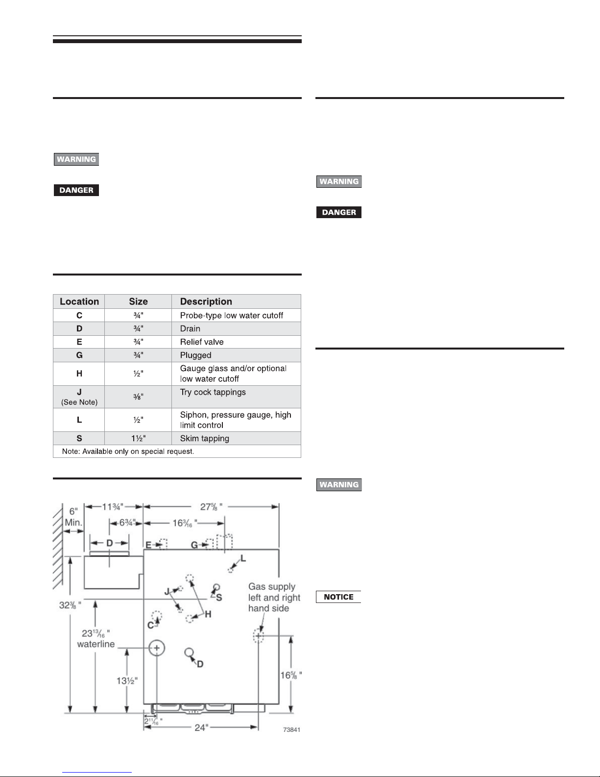
3. Remove plugs from any tappings that will be used for controls
and accessories. Refer to Table 4 and Figure 3, below.
Table 4 Control tapping
Figure 3 Control tapping locations
Draft diverter installation
1. Secure draft diverter to flue collector hood with sheet metal
screws. See Figure 16, items 1 and 9, on page 26. Use boiler
cement to provide gas tight seal.
Failure to maintain gas-tight seal can cause flue gas
spillage and carbon monoxide emissions, resulting
in severe personal injury or death.
Do not alter boiler draft diverter or place any
obstruction or non-approved vent damper in
breeching or vent system. CSA certification will
become void. Flue gas spillage and carbon monoxide
emissions will occur causing severe personal injury
or death.
Spill switch installation
1. Fasten spill switch to draft diverter as shown in Figure 16, item
20, page 26.
2. See Wiring diagram on page 17 to connect wires.
Install vent piping
1. Connect from draft diverter or vent damper outlet to chimney or
vent with same size vent connector.
2. Where possible, vertical venting to the outside from the draft
diverter or vent damper outlet will offer best performance.
3. Where horizontal vent connector is used, slope upward at least
¼" per lineal foot toward chimney or vent and support with
hangers to prevent sagging.
4. Breeching must not be connected to any portion of a mechanical
draft system that can operate under positive pressure.
Long horizontal vent connector, excessive number
of elbow or tees, or other obstructions that restrict
the flow of combustion gases should be avoided.
Severe personal injury, death or substantial property
damage could result.
Float-type low water cutoff — If field installing a floattype low water cutoff, it must be piped only to the
gauge glass tappings, items H, Figure 3. The tappings
are spaced 9" on center. Use only float-type low water
cutoffs with quick-connect hookups that will provide
a low water cutoff point no higher than 2" above the
center of the bottom tapping. See page 11, Figure 9,
for a typical installation.
7Part Number 550-110-738/0703
Page 8

GSA
Gas-Fired Steam Boilers – Boiler Manual
2 Prepare boiler continued
Vent damper
These systems are used on gas-fired boilers with
vent dampers as shipped from factory. Boiler will not
operate without vent damper installed.
Damper blade
See vent manufacturer’s instructions to install plug (shipped with
damper) in damper hole. Install plug with
damper hole.
Minimum clearances
Provide a minimum of 6" between the vent damper and any
combustible material. (See “Minimum clearance to combustible
materials,” page 3, for minimum clearance from jacket top to ceiling
to maintain this dimension.)
Damper installation
Do not modify draft diverter or vent damper, or make
another connection between draft diverter and vent
damper or boiler except as noted below. This will void
CSA certification and will not be covered by warranty.
Any changes will cause severe personal injury, death
or substantial property damage.
1. Install vent damper as shown in vent damper manufacturer’s
instructions. Vent damper must be installed so that it serves
only one boiler and so damper blade indicator is visible to the
user. See Figure 4.
2. Screws or rivets used to secure the vent damper to the draft
diverter must not interfere with rotation of the damper blade.
3. Install damper harness between damper actuator and knockout
in jacket top panel. Use strain relief connectors and locknuts to
secure both ends of damper harness.
Keep wiring harness clear of all hot surfaces. Wire
insulation could be damaged, causing risk of electrical
short-circuit.
3
/
8" diameter hole in vent
4. Read and apply the harness plug warning label (shown above)
so that it is visible after installation
5. Plug damper harness receptacle into damper harness plug.
Bypassing (jumpering) vent damper will cause flue
products such as carbon monoxide to escape into
the house. This will cause severe personal injury or
death.
After boiler has operated once, if either end of harness
is disconnected, the system safety shutdown will
occur. The boiler will not operate until harness is
reconnected.
Effikal damper — Damper hold open switch must be
in Automatic Operation position for system to operate
properly.
Figure 4 Vent damper assemblies
8 Part Number 550-110-738/0703
Page 9

3 Install piping
GSA
Gas-Fired Steam Boilers – Boiler Manual
General
1. Pipe before installing controls. Connect return piping after jacket
is attached. Connect supply piping before or after jacket is
attached.
Failure to properly pipe the boiler may result in
improper operation and damage to the boiler or
building.
2. See Figure 5 and Table 5. Pipe exactly as shown. Satisfactory
operation of a steam heating system depends on adequate
condensate return to boiler to maintain a steady water level.
Avoid adding raw makeup water. Where condensate return is
not adequate, install low water cutoff/pump control, condensate
receiver and condensate boiler feed pump. Refer to Table 7,
page 10, for sizing. See page 7, Table 4, for tapping locations.
Figure 5 Recommended piping, piping for parallel-
flow systems only.
Connecting to counterflow piping
Apply the recommended piping in Figures 4 through 7 only when
connecting to a parallel-flow system. When connecting to a
counterflow system, the boiler steam supply must connect into the
top of the counterflow system header, as shown in Figure 6.
Figure 6 Connection to counterflow steam piping
Table 5 Recommended pipe sizing
Boiler model number Riser (A) Header (H)
GSA-075 and GSA-100 2" 2" 1½"
GSA-125 through GSA-175 2½" 2 ½" 1½"
GSA-200 and GSA-250 3" 3" 1½"
Note: 24" minimum from waterline to header.
see Note
Equalizer (J)
Relief valve
Install relief valve in tapping on top of boiler. See Table 4, page 7,
for control tapping locations. See the tag attached to the relief valve
for manufacturer’s instructions.
Follow the steps below to avoid potential severe
personal injury, death or substantial property damage.
• When installing the relief valve, ensure that all
connections, including the valve inlet, are clean and
free from any foreign matter.
• Mount the relief valve only in the vertical position,
directly connected to the tapping designated in the
manual on top of the boiler.
• Use pipe compound sparingly, or tape, on external
threads only.
• Do not use a pipe wrench! Use proper type and size
wrench on wrench pads only.
9Part Number 550-110-738/0703
Page 10

GSA
Gas-Fired Steam Boilers – Boiler Manual
3 Install piping continued
Relief valve continued
During operation, this valve may discharge large
amounts of steam and/or hot water. Therefore, to
reduce the potential for bodily injury and property
damage, a discharge line MUST be installed that:
• Is connected from the outlet to a safe point of
discharge with no intervening valve.
• Allows complete drainage of both the valve and the
discharge line.
• Is independently supported and securely anchored
so as to avoid applied stress as possible.
• Terminates freely to atmosphere where any
discharge will be clearly visible and is at no risk of
freezing.
• Is, over its entire length, of a pipe size equal to or
greater than that of the valve outlet.
Use only schedule 40 metal pipe for discharge. (Do
not use schedule 80, extra strong or double strong
pipe or connections.) DO NOT CAP, PLUG OR
OTHERWISE OBSTRUCT DISCHARGE PIPE
OUTLET! If discharge is piped upward, a condensate
drain must be provided in the elbow below the vertical
pipe to prevent condensate from returning into the
valve. Failure to comply with these instructions will
cause a dangerous spray of hot water and steam
that would cause severe personal injury or death.
Table 6 Reservoir pipe sizing
Boiler
model
number
GSA-075 75
GSA-100 100
GSA-125 125
GSA-150 150
GSA-175 175 1¾
GSA-200 200 2
GSA-250 250 2½
Designed full capacity steaming time of modern boilers is 10 minutes.
Boiler
gross
output
MBH
Time from initial steaming to average condensate
return (boiler steaming capacity based on 970 Btu per
15 minutes 20 minutes 30 minutes
gallons
1
1
1¼
1½ 1½ 3 2½
pipe
length
(feet)
1
1
1¼
1¾
2
2¼
pound of steam)
gallons
pipe
length
(feet)
1½
1½
2
2½
2
2¼
Use boiler feed system
gallons
pipe
length
(feet)
Use boiler feed
system
Condensate return
Modern steam boilers are designed to steam for less time than
older, larger boilers. When replacing an older steam boiler the system
condensate return time may be longer than the steaming time. This
could cause the following problems:
1. Boilers fitted with an automatic water feed could overfill.
2. Units fitted with only a low water cutoff would shut down and
cycle while waiting for condensate to return.
Following is a simple method for determining whether or not a
reservoir pipe is required to lengthen steaming time for a residential
installation:
1. Disconnect condensate return line at existing boiler.
2. Heat boiler and allow to steam for 10 minutes. Turn off boiler.
3. Measure length of time from when boiler started to steam to
when condensate begins to return through condensate line.
4. Measure length of time from when condensate begins to return
to when it stops returning. Divide this time by 2.
5. Add time measured in step 3 to time calculated in step 4. This
sum is the average time required for condensate to return to
the boiler.
6. If this total time is 10 minutes or less, no reservoir pipe is needed.
If total time for condensate to return to boiler (from step 5) is more
than 10 minutes, a reservoir pipe (or boiler feed system) is
recommended. See Table 6, this page, for suggested reservoir pipe
size. Install as shown in Figure 7, below.
For larger systems (as noted in Table 6), use a boiler feed system
with a condensate tank and feed pump. You will have to install a low
water cutoff/pump control on the boiler to operate the pump. Use
Table 7 to size boiler feed systems. See page 7, Table 4, for tapping
locations. (The use of a combination condensate tank and floatcontrolled condensate return pump is not recommended.)
For most residential installations a reservoir pipe may be all that is
necessary to ensure proper operation.
Figure 7 Recommended piping for parallel-flow
systems with optional reservoir pipe
Table 7 Boiler feed system sizing
Boiler
model
number
GSA-075 63 8 2 4 6 8 0.2
GSA-100 81 10 3 6 9 12 0.3
GSA-125 102 12 4 7 11 14 0.4
GSA-150 122 15 5 9 14 18 0.5
GSA-175 142 17 5 10 15 20 0.6
GSA-200 163 20 6 12 18 24 0.7
GSA-250 203 24 7 14 22 29 0.8
Notes
1. Maximum time to when condensate returns to boiler.
2. If pump capacity exceeds capacity shown, pump can be throttled with globe or
ball valve.
I=B=R
gross
output
(pounds
steam
per hour)
Conden-
sate
(gallons
per hour)
Minimum condensate receiver
capacity gallons for boiler
steaming times (minutes) of:
15 min. 30 min. 45 min. 60 min.
(note 1)
10 Part Number 550-110-738/0703
Suggested
feed pump
capacity
(GPM @
15 PSI)
(note 2)
Page 11
4 Install controls
Controls
GSA
Gas-Fired Steam Boilers – Boiler Manual
Failure to properly install, pipe and wire boiler controls
may result in severe damage to the boiler, building
and personnel.
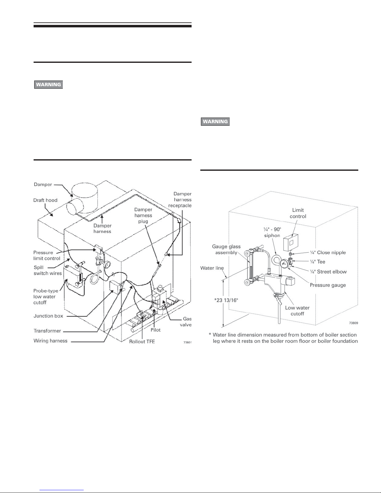
1. Controls are mounted and wired as shown in Figure 8. for actual
tapping locations see Table 4 and Figure 3 on page 7.
2. Bring supply wiring to boiler. Must be 14 gauge or heavier.
3. See wiring diagram on page 17.
Figure 8 Controls
Float-type low water cutoff (when provided by others)
1. Install low water cutoff as shown in Figure 9, below. See Table 4
and Figure 3 on page 7 for actual tapping location.
2. Install blowdown line in bottom of cutoff. See control
manufacturer’s instructions for details.
Pipe blowdown line near floor close to floor drain to
eliminate potential of severe burns. Do not plug, valve
or place any obstruction in blowdown line.
3. Water feeders are not recommended for primary control. A low
water cutoff with pump controller is recommended with a
condensate receiver and feed pump.
Figure 9 Float-type low water cutoff
(when provided by others)
11Part Number 550-110-738/0703
Page 12
GSA
Gas-Fired Steam Boilers – Boiler Manual
5 Install gas piping
Connecting gas supply piping to boiler
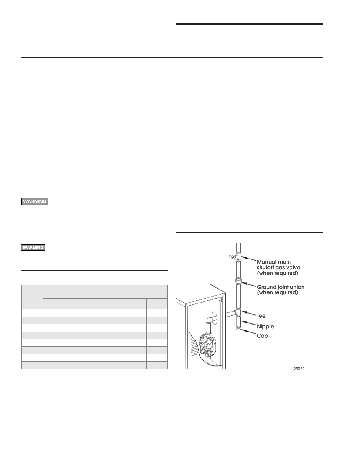
1. Remove jacket front panel and see Figure 10 to pipe gas to
boiler.
a. Install drip leg at inlet of gas connection to boiler. Where
local utility requires drip leg to be extended to the floor, use
appropriate length of nipple between cap and tee.
b. Install ground joint union for servicing, when required.
c. Install manual shutoff valve in gas supply piping outside
boiler jacket when required by local codes or utility
requirements.
d. In Canada — When using manual main shutoff valve, it must
be identified by the installer.
2. Support piping with hangers, not by boiler or its accessories.
3. Purge all air from gas supply piping.
4. Before placing boiler in operation, check boiler and its gas
connection for leaks.
a. Close manual main shutoff valve during any pressure
testing at less than 13" w.c.
b. Disconnect boiler and gas valve from gas supply piping
during any pressure testing greater than 13" w.c.
Do not check for gas leaks with an open flame —
Use bubble test. Failure to use bubble test or check
for gas leaks can cause severe personal injury, death
or substantial property damage.
5. Use pipe dope compatible with propane gases. Apply sparingly
only to male threads of pipe joints so that pipe dope does not
block gas flow.
Failure to apply pipe dope as described in this manual
can result in severe personal injury, death or
substantial property damage.
Natural Gas:
1. See Table 8 for pipe length and diameter. Base on rated boiler
input, found on page 31 (divide by 1,000 to obtain cubic feet per
hour). Table 8 is only for gas with specific gravity 0.60, with a
pressure drop through the gas piping of 0.30" w.c. For additional
gas pipe sizing information, see ANSI Z223.1 (B149.1 or B149.2
for Canadian installations).
2. Inlet pressure required at gas valve inlet:
• Maximum: 13" w.c.
• Minimum: 5" w.c.
• Manifold gas pressure: 3.5" w.c.
3. Install 100% lockup gas pressure regulator in supply line if inlet
pressure exceeds 13" w.c. Adjust for 13" w.c. maximum.
Propane Gas:
1. Contact gas supplier to size pipes, tanks and 100% lockup gas
pressure regulator.
2. Adjust propane supply regulator provided by gas supplier for
13" w.c. maximum pressure.
3. Inlet pressure required at gas valve inlet:
• Maximum: 13" w.c.
• Minimum: 11" w.c.
• Manifold gas pressure: 10" w.c.
Figure 10 Gas supply piping
Table 8 Pipe capacity for 0.60 specific gravity natural gas
Gas
pipe
length
(feet)
10 132 278 520 1050 1600 3050
20 92 190 350 730 1100 2100
30 73 152 285 590 860 1650
40 63 130 245 500 760 1450
50 56 115 215 440 670 1270
75 45 93 175 360 545 1020
100 38 79 150 305 460 870
150 31 64 120 250 380 710
½" ¾" 1" 1¼" 1½" 2"
Capacity of pipe for pipe size of:
Capacity in standard cubic feet gas per hour)
(
12 Part Number 550-110-738/0703
Page 13
6 Field wiring
GSA
Gas-Fired Steam Boilers – Boiler Manual
For your safety, turn off electrical power supply at
service entrance panel before making any electrical
connections to avoid possible electric shock hazard.
Failure to do so can cause severe personal injury or
death.
Wiring must be N.E.C. Class 1.
If rollout thermal fuse element wire supplied with boiler
must be replaced, type 200 °C wire or equivalent
must be used. If other original wiring supplied with
boiler must be replaced, use only type 105 °C wire or
equivalent.
Boiler must be electrically grounded as required by
National Electrical Code ANSI/NFPA 70–latest edition.
Electrical installation must comply with:
1. National Electrical Code and any other national, state, provincial
or local codes or regulations.
2. In Canada, CSA C22.1 Canadian Electrical Code Part 1, and
any local codes.
Wiring connections
Boiler is shipped with controls completely wired, except spill switch
and vent damper. See wiring diagram on page 17 for standing pilot
ignition boiler.
Thermostat
1. Connect thermostat as shown on wiring diagram on boiler.
2. Install on inside wall away from influences of drafts, hot or cold
water pipes, lighting fixtures, television, sunrays or fireplaces.
3. If thermostat has a heat anticipator, set heat anticipator in
thermostat to match power requirements of equipment
connected to it. If connected directly to boiler, set for 0.4 amps.
For other devices, see manufacturer’s specifications. Wiring
diagram on boiler gives setting for control module and gas valve.
Also see instructions with thermostat.
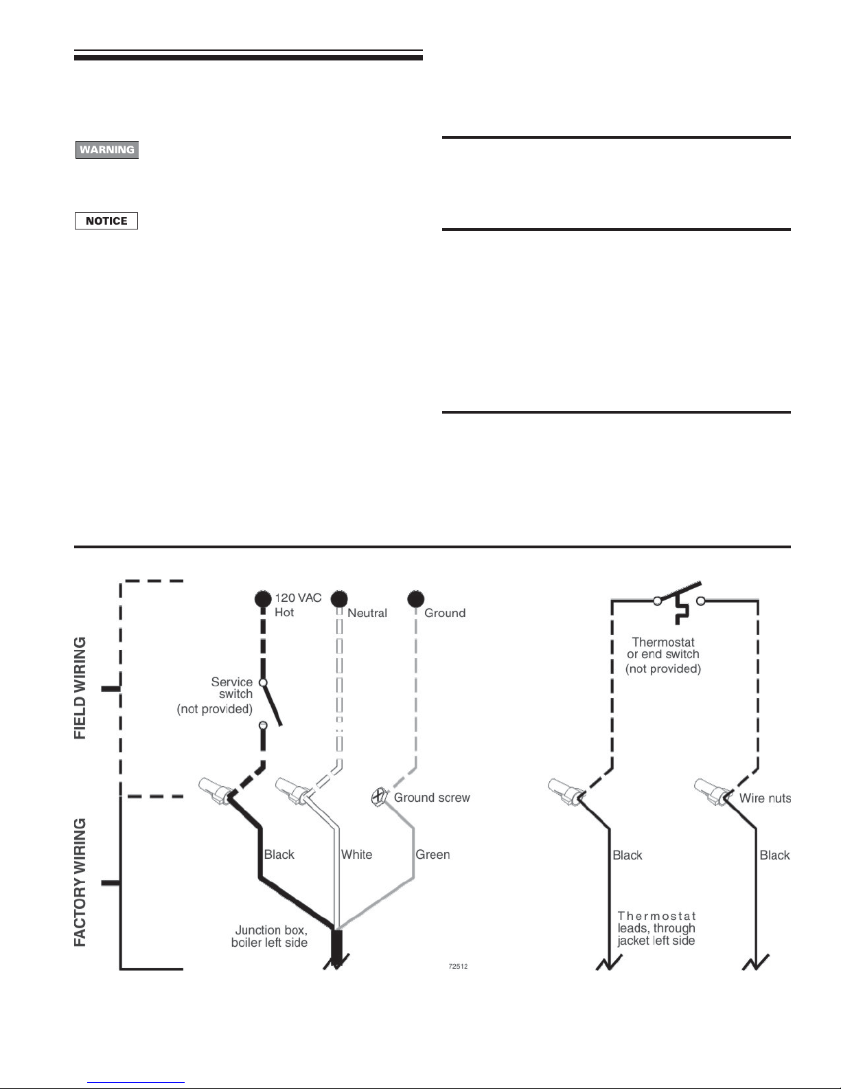
Junction box
1. Connect 120 VAC power wiring (Figure 11). A separate electrical
circuit with a fused disconnect switch (15 amp. recommended)
should be used for the boiler.
Figure 11 Field wiring connections — service switch and thermostat (or end switch) provided by installer
13Part Number 550-110-738/0703
Page 14
GSA
Gas-Fired Steam Boilers – Boiler Manual
7 Start-up
Preparation
Check for gas leaks
Before starting the boiler, and during initial operation,
smell near the floor and around the boiler for gas
odorant or any unusual odor. Do not proceed with
start-up if there is any indication of a gas leak. Repair
any leak at once.
Propane boilers only — Your propane supplier mixes
an odorant with the propane to make its presence
detectable. In some instances, the odorant can fade
and the gas may no longer have an odor.
• Propane gas can accumulate at floor level. Smell near
the floor for the gas odorant or any unusual odor. If
you suspect a leak, do not attempt to light the pilot.
• Use caution when attempting to light the propane pilot.
This should be done by a qualified service technician,
particularly if pilot outages are common.
• Periodically check the odorant level of your gas.
• Inspect boiler and system at least yearly to make
sure all gas piping is leak-tight.
• Consult your propane supplier regarding installation
of a gas leak detector. There are some products on
the market intended for this purpose. Your supplier
may be able to suggest an appropriate device.
Determine if water treatment is needed
Do not use petroleum-based cleaning or sealing
compounds in boiler system. Severe damage to
boiler will occur, resulting in substantial property
damage.
Eliminate all system leaks. Continual fresh makeup
water will reduce boiler life. Minerals can build up in
sections, reducing heat transfer, overheating cast
iron, and causing section failure.
Consult local water treatment companies for unusually hard water
areas (above 7 grains hardness) or low pH water conditions (below
7.0). Boiler water pH of 7.0 to 8.5 is recommended.
Fill the system with water
1. Do not fill (except for leakage tests) until boiler is ready to be
fired.
2. Fill to normal waterline, halfway up gauge glass.
3. Boiler water pH 7.0 to 8.5 is recommended.
4. Follow skimming procedure, right.
Skimming the boiler
Clean all newly installed steam boilers to remove
oil and grease. Failure to properly clean can result
in violent fluctuations of water level, water passing
into steam mains or high maintenance costs on
strainers, traps and vents.
Do not use petroleum-based cleaning or sealing
compounds in boiler system. Severe damage to boiler
will occur, resulting in substantial property damage.
1. Provide 1½" piping from skim tapping to floor drain.
2. Adjust waterline to midpoint of skim tapping. See Figure 3,
page 7.
3. Follow “Lighting Instructions” found on boiler or on pages 18
and 19 of this manual, to fire boiler to maintain temperature below
steaming rate.
4. Feed in water to maintain water level. Cycle burners to prevent
rise in steam pressure.
5. Continue skimming until discharge is clear. May take several
hours.
6. Drain boiler. While boiler is warm, but not hot, flush all interior
surfaces under full pressure until drain water runs clear.
7. Remove skim piping. Plug tapping.
8. Close drain cock. Fill with fresh water to waterline. Start burners
and steam for 15 minutes to remove dissolved gases. Stop
burners.
9. Check traps and air vents for proper operation.
10. Process may need to be repeated after several weeks of
operation.
Inspect base insulation
The boiler contains ceramic fiber and fiberglass
materials. Use care when handling these materials
per instructions on page 32 of this manual. Failure
to comply could result in severe personal injury.
Check to make sure insulation is secure against all four sides of
the base. If insulation is damaged or displaced, do not operate
boiler. Replace or reposition insulation.
Failure to replace damaged insulation or reposition
insulation can result in a fire hazard, causing severe
personal injury, death or substantial property
damage.
14 Part Number 550-110-738/0703
Operate boiler
DO NOT proceed with boiler operation unless boiler
and system have been filled with water and all
instructions and procedures of previous manual
sections have been completed. Failure to do so could
result in severe personal injury, death or substantial
property damage. Before starting the boiler . . .
• See pages 18 and 19, for “Lighting Instructions”.
• Verify the boiler and system water level is correct
(no more than ½ of gauge glass or less than ¼" above
bottom of gauge glass).
• Verify the “Preparation” procedures, on this page,
have been completed.
Page 15
7 Start-up continued
GSA
Gas-Fired Steam Boilers – Boiler Manual
Operate boiler continued
Start the boiler
1. Check boiler water level — Should be approximately ½ way up
gauge glass.
2. Remove boiler jacket door and note the gas valve manufacturer
and model number.
3. Follow the “Lighting Instructions” on page 18 or 19, depending
on gas valve installed in boiler. Use only the “Lighting Instruction”
which applies to this gas valve. (The “Lighting Instruction” label
on the boiler provides the same information.)
4. If boiler fails to start, see “If boiler doesn’t start . . . Check for:”
on this page.
Check system and boiler
Eliminate all system leaks. Continual fresh makeup
water will reduce boiler life. Minerals can build up in
sections, reducing heat transfer, overheating cast iron,
and causing section failure.
If you discover evidence of any gas leak, shut down
the boiler at once. Find the leak source with bubble
test and repair immediately. Do not start boiler again
until corrected. Failure to comply could result in
severe personal injury, death or substantial property
damage.
Do not use petroleum-based cleaning or sealing
compounds in boiler system. Severe damage to boiler
will occur, resulting in substantial property damage.
1. Check system piping for leaks. If found, shut down boiler and
repair immediately.
2. Inspect vent system thoroughly for signs of deterioration from
corrosion, physical damage or sagging. Verify that masonry
chimney liners are in good condition, with no obstructions, and
there are no openings into the chimney.
3. Check around the boiler for gas odor following the procedure of
“Check for gas leaks”, page 14.
4. Verify operation using procedures below. Perform “Checkout
procedure”, page 16, and fill in the “Installation and service
certificate”.
If boiler doesn’t start . . . Check for:
1. Loose connections, blown fuse or service switch off?
2. High limit switch set below boiler pressure?
3. Thermostat set below room temperature?
4. Gas not turned on at meter or boiler?
5. Incoming gas pressure less than:
5" w.c. for natural gas? 11" w.c. for propane gas?
6. If none of the above corrects the problem, see “Troubleshooting”,
page 24.
Verify operation
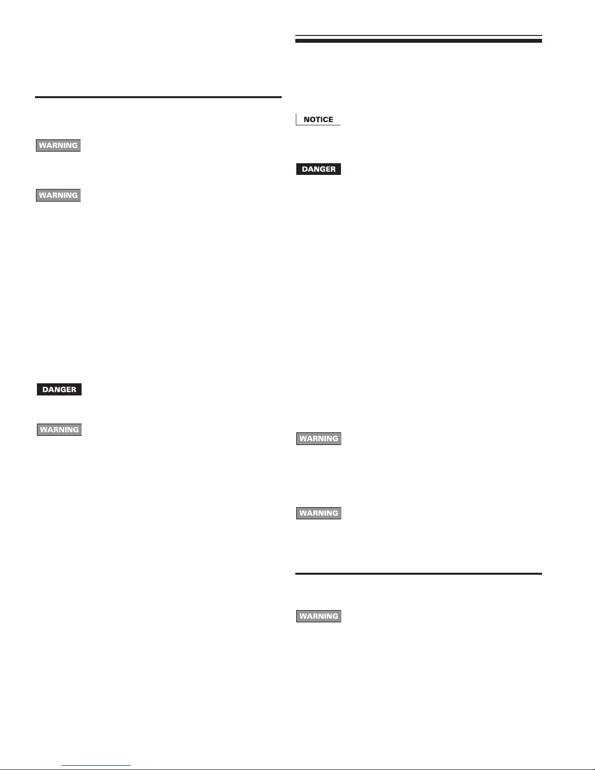
Check burner flame — Pilot burner
Proper pilot flame (see Figure 12):
1. Blue flame.
2. Inner cone engulfing thermocouple.
3. Thermocouple glowing cherry red.
Improper pilot flame:
1. Overfired — Large flame lifting or blowing past thermocouple.
2. Underfired — Small flame. Inner cone not engulfing
thermocouple.
3. Lack of primary air — Yellow flame tip.
4. Incorrectly heated thermocouple.
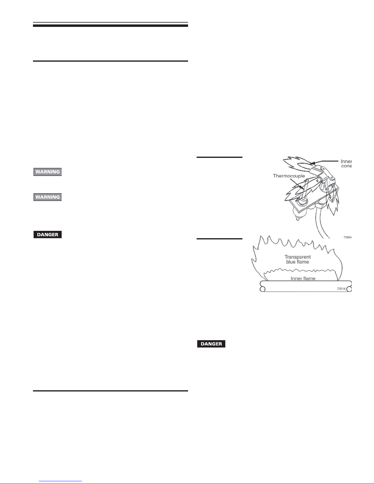
Check burner flames — Main burner
Proper main burner flame (see Figure 13):
1. Yellow-orange streaks may appear (caused by dust).
Improper main burner flame:
1. Overfired — Large flames.
2. Underfired — Small flames.
3. Lack of primary air — Yellow tipping on flames (sooting will
occur).
Figure 12
Typical pilot
burner flame
Figure 13
Typical main
burner flame
Check vent damper operation
1. Raise room thermostat to call for heat — Vent damper actuator
will slowly open vent damper.
2. When vent damper is fully open — Main gas valve will open
and main burners will ignite.
Vent damper must be fully open before main burners
light. If vent damper does not fully open, flue products
such as carbon monoxide will escape into house,
causing severe personal injury or death.
3. Lower thermostat setting — Main burner flames will go out, then
vent damper will close.
4. Repeat Steps 2 through 4 several times to verify operation.
5. Return thermostat to normal setting.
6. Set thermostat heat anticipator setting indicated on wiring
diagram.
Check venting system operation
1. With boiler firing, hold a candle or match below lower edge of
draft diverter “skirt.” If flame does not blow out, but burns
undisturbed, the vent system is working properly. If flame blows
out or flickers severely, the vent system must be checked for
obstructions or other causes of improper venting.
15Part Number 550-110-738/0703
Page 16

GSA
Gas-Fired Steam Boilers – Boiler Manual
8 Checkout procedure
❏ Boiler filled with water?
❏ Boilers properly skimmed?
❏ Air purged from gas piping? Piping checked for leaks?
❏ Correctly-sized manifold orifices installed? See Table 3, page 6,
to check size and fuel type.
Correctly sized manifold orifices must be used. Failure
to do so will cause severe personal injury, death or
substantial property damage.
❏ Button on spill switch pushed in?
❏ Followed “Lighting Instructions” on boiler or in Manual Section
10, pages 18 and 19, for proper start-up?
❏ Proper burner flame observed? See “Verify operation”, page 15.
❏ Test limit control — While burners are operating, move indicator
on limit control below actual boiler pressure. Burners should go
off. Raise setting on limit control above boiler pressure and
burners should reignite.
❏ Test low water cutoff — Check probe-type low water cutoff for
proper operation.
a. Turn off power to boiler and wait 5 minutes.
b. Drain water to bottom of gauge glass.
c. Turn on power.
d. Set thermostat to call for heat. Red neon lamp on lower
water cutoff should light.
e. Wait 5 minutes. Boiler should not fire.
f. Refill boiler to correct water line. Red lamp should go off.
g. Wait 5 minutes. Boiler should fire.
h. Return thermostat to normal setting.
❏ Test additional field-installed controls — If boiler has an additional
high limit, low water cutoff or other controls, test for operation
as outlined by manufacturer. Burners should be operating and
should go off when controls are tested. When controls are
restored, burners should reignite.
❏ Test ignition system safety device — Turn gas cock knob to
PILOT position and extinguish pilot flame. Pilot gas flow should
stop in less than 3 minutes. Put system back into operation
(see Section 7, pages 14-15).
❏ Set limit control(s) to system pressure requirements. Adjust
balancing valves and controls to provide design pressure to
system.
❏ Verify thermostat heat anticipator (if available) set properly? See
“Thermostat”, page 13.
❏ Cycle boiler with thermostat — Raise to highest setting and
verify boiler goes through normal start-up cycle. Lower to lowest
setting and verify boiler goes off.
❏ Measure natural gas input:
a. Operate boiler 10 minutes.
b. Turn off other appliances.
c. At natural gas meter, measure time (in seconds) required
to use one cubic foot of gas.
d. Calculate gas input:
3600 x 1000
number of seconds from step c
e. Btuh calculated should approximate input rating on boiler
rating label.
= Btuh
❏ Check manifold gas pressure by connecting manometer to
downstream test tapping on main gas valve. Manifold pressure
for natural gas should be 3.5" w.c. and for propane gas should
be 10" w.c.
❏ Observe several operating cycles for proper operation.
❏ Set room thermostat to desired room temperature.
❏ Fill in “Installation and service certificate” below?
❏ Review all instructions shipped with this boiler with owner or
maintenance person. Return instructions to envelope and give
to owner or place in pocket inside front panel in boiler.
Installation and service certificate
Boiler model _______________________________________________________________ Series ____________
CP number _______________________________________ Date installed _________________________________
Measured Btuh input ____________
Installer _______________________ ______________________________ ____________________________
(company) (address) (phone)
16 Part Number 550-110-738/0703
Installation instructions have been followed.
Checkout sequence has been performed.
Above information is certified to be correct.
Information received and left with owner/maintenance person.
_____________________________________
(installer’s signature)
Page 17
GSA
Gas-Fired Steam Boilers – Boiler Manual
energizes the main gas valve. This provides gas to the main burners. Burners remain
ignited until thermostat circuit or limit circuit opens. Burners are deenergized when call
for heat stops.
the limit circuit closes again, the main gas valve is energized if there is still a call for
heat.
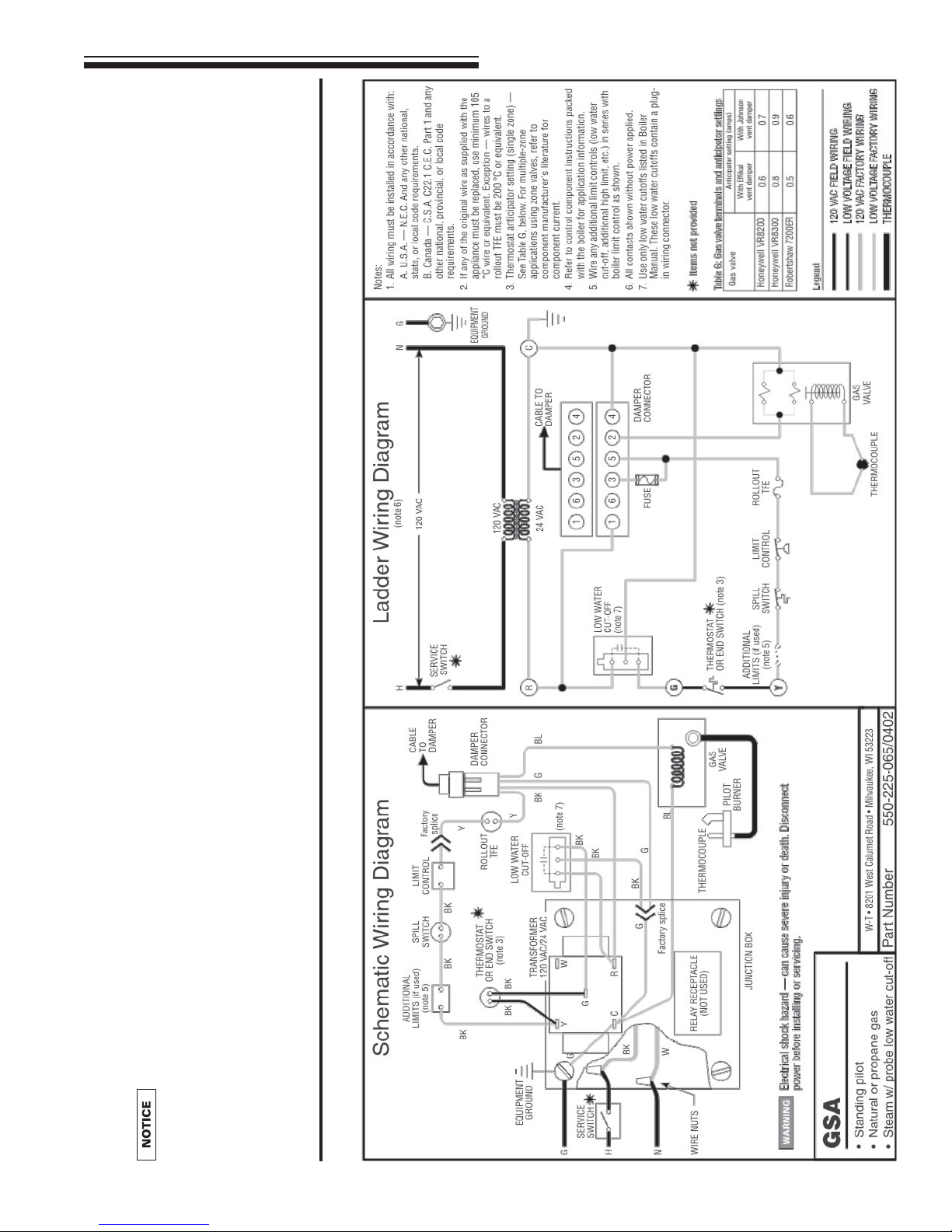
Figure 14.
3. Limit operation: When a limit control opens, the main gas valve is deenergized. When
4. Thermostat heat anticipator: Set heat anticipator as shown on wiring diagram,
Follow all procedures given in this manual and “Lighting Instructions” when
operating the boiler. Failure to do so could result in severe personal injury,
death or substantial property damage.
maintains pilot as long as the thermocouple is satisfied. If thermocouple signal drops
for any reason, pilot must be manually lighted, following the “Lighting Instructions” in
this manual and on boiler. Vent damper will remain closed until a call for heat.
The vent damper drives open. When the vent damper is fully open, its end switch
9 Sequence of operation
1. Standby mode: After pilot is manually lighted, the gas valve provides pilot gas and
2. Call for heat: When thermostat circuit closes, the boiler vent damper is energized.
Figure 14 Wiring diagram — Standing pilot system
17Part Number 550-110-738/0703
Page 18
GSA
Gas-Fired Steam Boilers – Boiler Manual
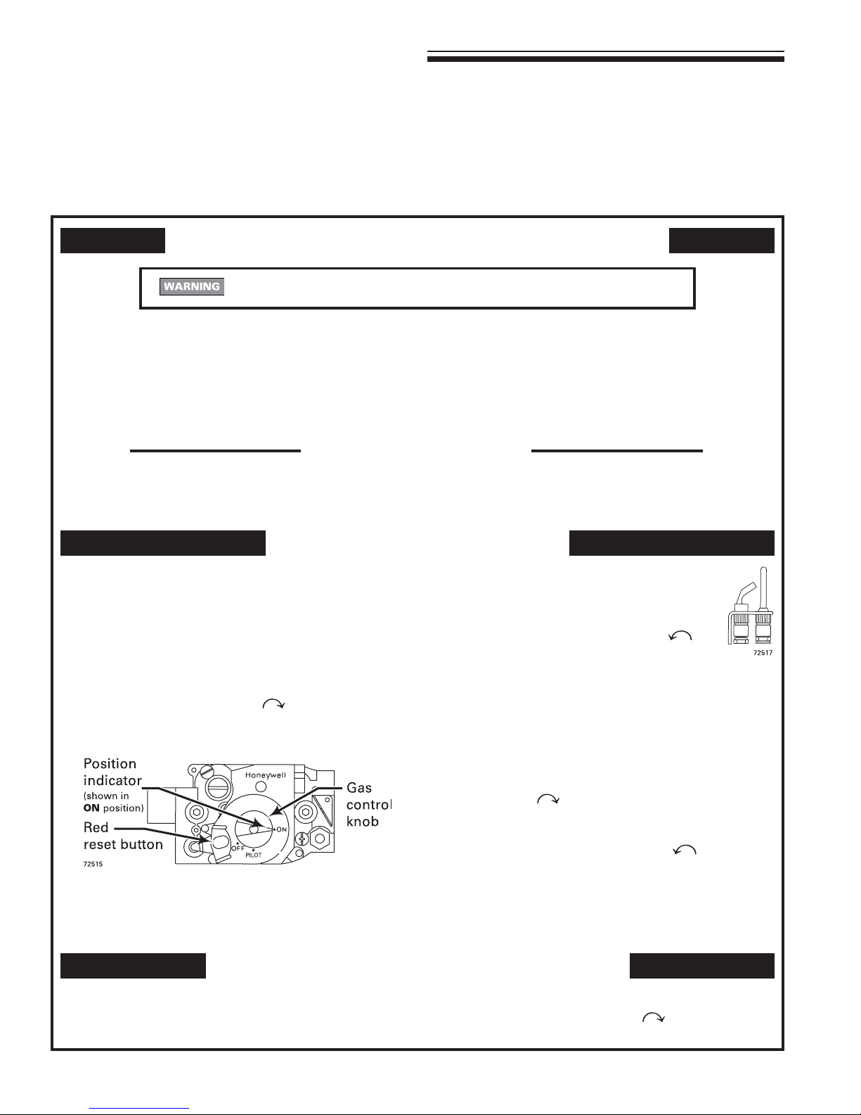
10 Lighting Instructions — GSA standing pilot boilers
Honeywell VR8200/VR8300 gas valve
FOR YOUR SAFETY READ BEFORE LIGHTING
If you do not follow these instructions exactly, a fire or explosion may result causing
property damage, personal injury or loss of life.
A. This appliance has a pilot, which must be
lighted by hand. When lighting the pilot, follow
these instructions exactly.
B. Before LIGHTING, smell all around the
appliance area for gas. Be sure to smell next
to the floor because some gas is heavier than
air and will settle on the floor. See below.
• Do not try to light any appliance.
• Do not touch any electric switch; do not use any phone in
your building.
C. Use only your hand to push down the reset button or turn the gas control
knob. Never use tools. If the knob or reset button will not operate by hand,
don't try to repair it, call a qualified service technician. Force or attempted
repair may result in a fire or explosion.
D. Do not use this appliance if any part has been under water. Immediately call
a qualified service technician to inspect the appliance and to replace any
part of the control system and any gas control, which has been under water.
WHAT TO DO IF YOU SMELL GAS
LIGHTING INSTRUCTIONS
1. Stop! Read the safety information above on this label.
2. Set the thermostat to lowest setting.
3. When equipped with Effikal vent damper Model RVGP, place
service switch in Hold Damper Open position.
4. Turn off all electrical power to the appliance.
5. When equipped with Johnson Controls vent damper Model
M35, manually rotate damper blade in direction of arrow to
Open position indicated on damper assembly.
6. Turn gas control knob clockwise
7. When equipped with vent damper, verify damper blade is in
full open position.
8. Wait five (5) minutes to clear out any gas. Then smell for
gas, including near the floor. If you smell gas, STOP! Follow
"B" in the safety information above. If you don't smell gas,
go to the next step.
to OFF.
• Immediately call your gas supplier from a neighbor’s phone.
Follow the gas supplier’s instructions.
• If you cannot reach your gas supplier, call the fire department.
9. Remove access panel located above burners.
10. Find pilot — follow metal tube from gas control.
The pilot is between two burners behind the
access panel.
11. Turn gas control knob counterclockwise
PILOT.
12. Push in red reset button and hold. Immediately light the pilot
with a match. Continue to hold reset button in for about one
(1) minute after the pilot is lit.
13. Release reset button. Pilot should remain lit. If pilot goes out,
repeat steps 6 through 13.
• If reset button stays depressed after release, stop and
immediately call your service technician or gas supplier.
• If the pilot will not stay lit after several tries, turn the gas control
knob clockwise
or gas supplier.
14. Replace access panel.
15. Turn gas control knob counterclockwise
16. Turn on all electric power to the appliance.
17. When equipped with Effikal vent damper, place service switch
in Automatic Operation position.
18. Set thermostat to desired setting.
19. Replace front panel.
to OFF and call your service technician
to
to ON.
TO TURN OFF GAS TO THE APPLIANCE
1. Set the thermostat to lowest setting.
2. Turn off all electric power to the appliance if service is to be
performed.
18 Part Number 550-110-738/0703
3. Remove front panel.
4. Turn gas control knob clockwise
5. Replace front panel.
to OFF.
Page 19
GSA
Gas-Fired Steam Boilers – Boiler Manual
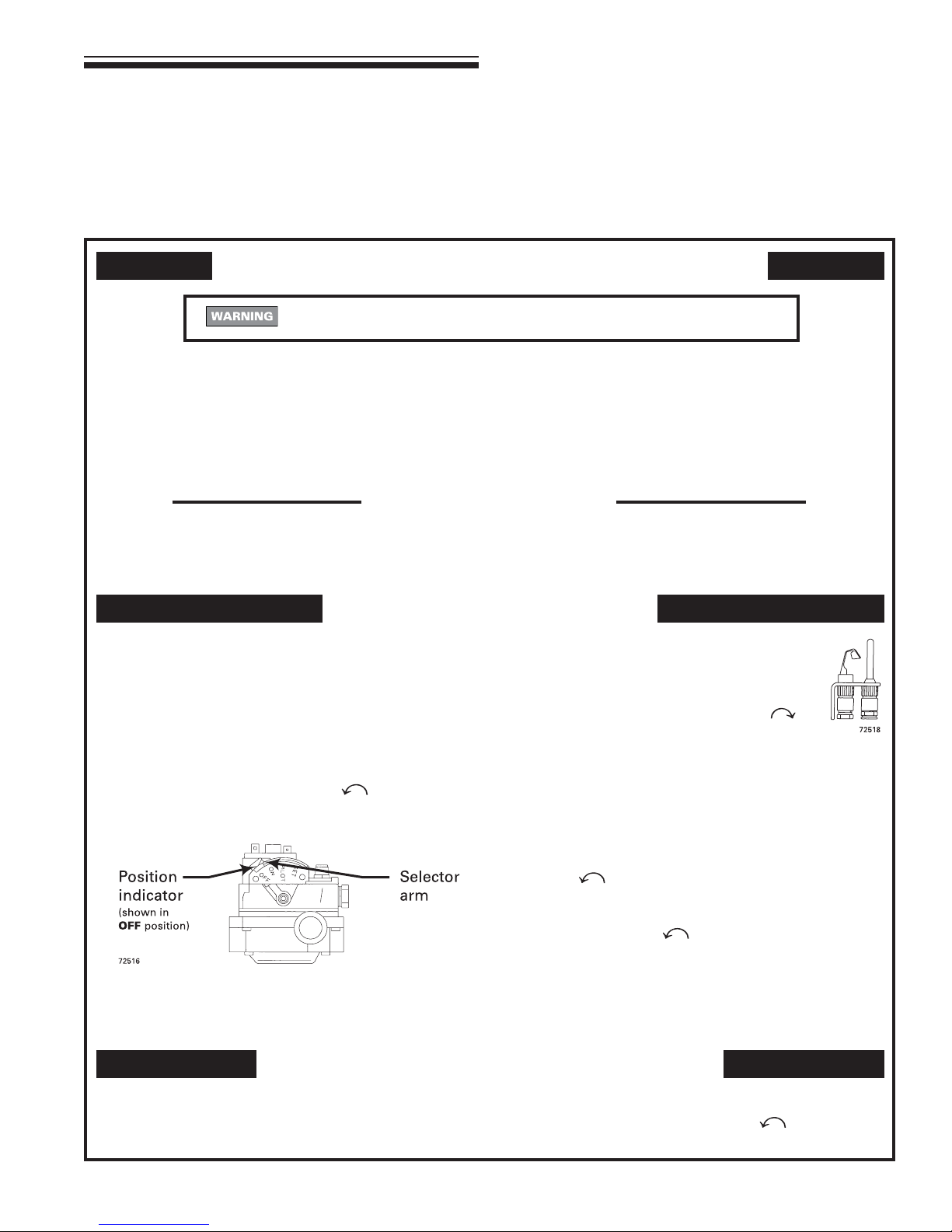
10 Lighting Instructions — GSA-30 through GSA-50
Robertshaw 7200 gas valve
FOR YOUR SAFETY READ BEFORE LIGHTING
If you do not follow these instructions exactly, a fire or explosion may result causing
property damage, personal injury or loss of life.
A. This appliance has a pilot, which must be
lighted by hand. When lighting the pilot, follow
these instructions exactly.
B. Before LIGHTING, smell all around the
appliance area for gas. Be sure to smell next
to the floor because some gas is heavier than
air and will settle on the floor. See below.
• Do not try to light any appliance.
• Do not touch any electric switch; do not use any phone in
your building.
C. Use only your hand to push down the reset button or turn the gas control
knob. Never use tools. If the knob or reset button will not operate by hand,
don't try to repair it, call a qualified service technician. Force or attempted
repair may result in a fire or explosion.
D. Do not use this appliance if any part has been under water. Immediately call
a qualified service technician to inspect the appliance and to replace any
part of the control system and any gas control, which has been under water.
WHAT TO DO IF YOU SMELL GAS
LIGHTING INSTRUCTIONS
1. Stop! Read the safety information above on this label.
2. Set the thermostat to lowest setting.
3. When equipped with Effikal vent damper Model RVGP, place
service switch in Hold Damper Open position.
4. Turn off all electrical power to the appliance.
5. When equipped with Johnson Controls vent damper Model
M35, manually rotate damper blade in direction of arrow to
Open position indicated on damper assembly.
6. Depress and move selector arm left
7. When equipped with vent damper, verify damper blade is in
full open position.
8. Wait five (5) minutes to clear out any gas. Then smell for
gas, including near the floor. If you smell gas, STOP! Follow
"B" in the safety information above. If you don't smell gas,
go to the next step.
to OFF.
• Immediately call your gas supplier from a neighbor’s phone.
Follow the gas supplier’s instructions.
• If you cannot reach your gas supplier, call the fire department.
9. Remove access panel located above burners.
10. Find pilot — follow metal tube from gas control.
The pilot is between two burners behind the
access panel.
11. Move selector arm on gas control right
to SET position.
12. Hold selector arm in SET position and immediately light the
pilot with a match. Continue to hold selector arm to SET for
about one-half (
13. Release selector arm. If pilot does not remain lit, repeat steps
6 through 13.
• If the pilot will not stay lit after several tries, move selector
arm left
supplier.
14. Replace access panel.
15. Turn selector arm left
16. Turn on all electric power to the appliance.
17. When equipped with Effikal vent damper, place service
switch in Automatic Operation position.
18. Set thermostat to desired setting.
19. Replace front panel.
1
/
) minute after the pilot is lit.
2
to OFF and call your service technician or gas
to ON.
TO TURN OFF GAS TO THE APPLIANCE
1. Set the thermostat to lowest setting.
2. Turn off all electric power to the appliance if service is to be
performed.
3. Remove front panel.
4. Depress and move selector arm left
5. Replace front panel.
to OFF.
19Part Number 550-110-738/0703
Page 20

GSA
Gas-Fired Steam Boilers – Boiler Manual
11 Service and maintenance
Table 9 Service and maintenance schedules (service technician and owner)
Service technician
(see following pages for instructions)
❏
Inspect:
• Reported problems
• Boiler area
• Air openings
• Flue gas vent system
• Pilot and main burner flames
• Piping
• Boiler heating surfaces
UP
-
• Burners and base
Service:
❏
START
• Gauge glass
Start-up:
❏
• Perform start-up per manual
NNNUAL
A
❏
Check/test:
Owner maintenance
(see User’s Information Manual for instructions)
❏ Daily • Check boiler area
• Check boiler pressure gauge
• Check air openings
❏ Monthly • Check boiler and system piping
• Check venting system
• Check/operate boiler relief valve
• Check pilot and main burner flames
❏ Periodically • Test low water cutoff
❏ End of season • Shut down procedure
• Gas piping
• Boiler waterline
• Limit controls and cutoffs
• Boiler relief valve
Review:
❏
• Review with owner
Follow the “Service and maintenance” procedures given throughout this manual and in component literature shipped with
the boiler. See “Read this first!” on page 2. Failure to perform the service and maintenance could result in damage to the
boiler or system. Failure to follow the directions in this manual and component literature could result in severe personal
injury, death or substantial property damage.
20 Part Number 550-110-738/0703
Page 21
GSA
Gas-Fired Steam Boilers – Boiler Manual
11 Service and maintenance continued
The boiler should be inspected and started annually,
at the beginning of the heating season, only by a
qualified service technician. In addition, the
maintenance and care of the boiler designated in Table
9, page 20 and explained on the following pages must
be performed to assure maximum boiler efficiency
and reliability. Failure to service and maintain the boiler
and system could result in equipment failure.
Electrical shock hazard — Turn off power to the boiler
before any service operation on the boiler except as
noted otherwise in this manual. Failure to turn off
electrical power could result in electrical shock,
causing severe personal injury or death.
The boiler contains ceramic fiber and fiberglass
materials. Use care when handling these materials
per instructions on page 32 of this manual. Failure to
comply could result in severe personal injury.
❏❏
❏ Inspect . . . . . . . . . .
❏❏
Reported problems
Inspect any problems reported by owner and correct before
proceeding.
Boiler area
1. Verify that boiler area is free of any combustible materials,
gasoline and other flammable vapors and liquids.
2. Verify that boiler area is free of any of the contaminants listed in
Table 2 on page 5 of this manual. If any of these are present in
the boiler intake air vicinity, they must be removed. If they cannot
be removed, install combustion air piping to the boiler in
accordance with national, provincial or local codes.
Air openings
1. Verify that combustion and ventilation air openings to the boiler
room and/or building are open and unobstructed. Check
operation and wiring of automatic combustion air dampers, if
used.
2. Verify that boiler vent discharge and air intake are clean and
free of obstructions.
Flue gas vent system
1. Visually inspect entire flue gas venting system for blockage,
deterioration or leakage. Repair any joints that show signs of
leakage in accordance with vent manufacturer’s instructions.
2. Verify that masonry chimneys are lined, lining is in good
condition, and there are not openings into the chimney.
Failure to inspect for the above conditions and have
them repaired can result in severe personal injury or
death.
Pilot and main burner flames
1. Visually inspect pilot burner and main burner flames as directed
under Section 7, page 15 of this manual.
❏❏
❏ Inspect . . . . . . . . . .
❏❏
Piping
1. Check the boiler interior piping and all system piping for
signs of leaks.
2. Repair any leaks before proceeding.
Do not use petroleum-based cleaning or sealing
compounds in boiler system. Severe damage to boiler
will occur, resulting in substantial property damage.
Eliminate all system or boiler leaks. Continual fresh
makeup water will reduce boiler life. Minerals can
build up in sections, reducing heat transfer,
overheating cast iron, and causing section failure.
Leaking water may also cause severe property
damage.
Boiler heating surfaces
The boiler contains ceramic fiber and fiberglass
materials. Use care when handling these materials
per instructions on page 32 of this manual. Failure
to comply could result in severe personal injury.
1. Disconnect the vent pipe at the boiler draft diverter and remove
draft diverter after turning off power to the boiler.
2. Use a bright light to inspect the boiler flue collector and
heating surfaces.
3. If the vent pipe or boiler interior surfaces show evidence of
soot, follow “Cleaning boiler heating surfaces”, page 23.
Remove the flue collector and clean the boiler if necessary
after closer inspection of boiler heating surfaces.
4. If there is evidence of rusty scale deposits on boiler surfaces,
check the water piping and control system to make sure the
boiler return water temperature is properly maintained (per
this manual).
5. Reconnect vent and draft diverter. Replace all boiler components
before returning to service.
6. Check inside and around boiler for evidence of any leaks from
the boiler. If found, locate source of leaks and repair.
Burners and base
1. After turning off power to the boiler, remove the jacket door
and base access panel (Figure 16, item 4, page 26).
2. Inspect burners and all other components in the boiler base.
3. If burners must be cleaned, raise rear of each burner to
release from support slot, slide forward and remove. Then
brush and vacuum the burners thoroughly, making sure all
ports are free of debris. Carefully replace all burners, making
sure burner with pilot bracket is replaced in its original position
and all burners are upright (ports up).
4. Inspect the base insulation.
a. Verify that the insulation is intact and secure against all
four sides of the base.
If insulation is damaged or displaced, do not
operate the boiler. Replace or reposition insulation
as necessary. Failure to replace damaged insulation
can result in a fire hazard, causing severe personal
injury, death or substantial property damage.
21Part Number 550-110-738/0703
Page 22
GSA
Gas-Fired Steam Boilers – Boiler Manual
11 Service and maintenance continued
❏❏
❏ Service. . . . . . . . . .
❏❏
Gauge glass
Normal waterline is halfway up gauge glass. Clean when needed.
1. Close lower gauge cock.
2. Open pet cock.
3. Open lower gauge cock and allow a small amount of water to
flush out through open pet cock.
4. Close pet cock.
5. Open lower gauge cock.
Boiler pressure must be low to eliminate potential of
severe burns.
If gauge glass breaks, close both gauge cocks.
Replace gauge glass. Do not replace with thin glass
tubing. Failure to comply could cause severe personal
injury, death or substantial property damage.
❏❏
❏ Start-up. . . . . . . . . .
❏❏
1. Perform “Start-up” procedures, Section 7, pages 14-15, including
“Verify operation” of burners and vent damper on page 15.
2. Check gas piping, per pages 12 and 14, verifying no indications
of leakage and all piping and connections are in good condition.
3. Read the “Lighting Instructions” (page 18 or 19, whichever
applies based on boiler gas valve).
4. Start the boiler following the “Lighting Instructions”, page 18
or 19.
❏❏
❏ Check/test. . . . . . . . . .
❏❏
Low water cutoffs
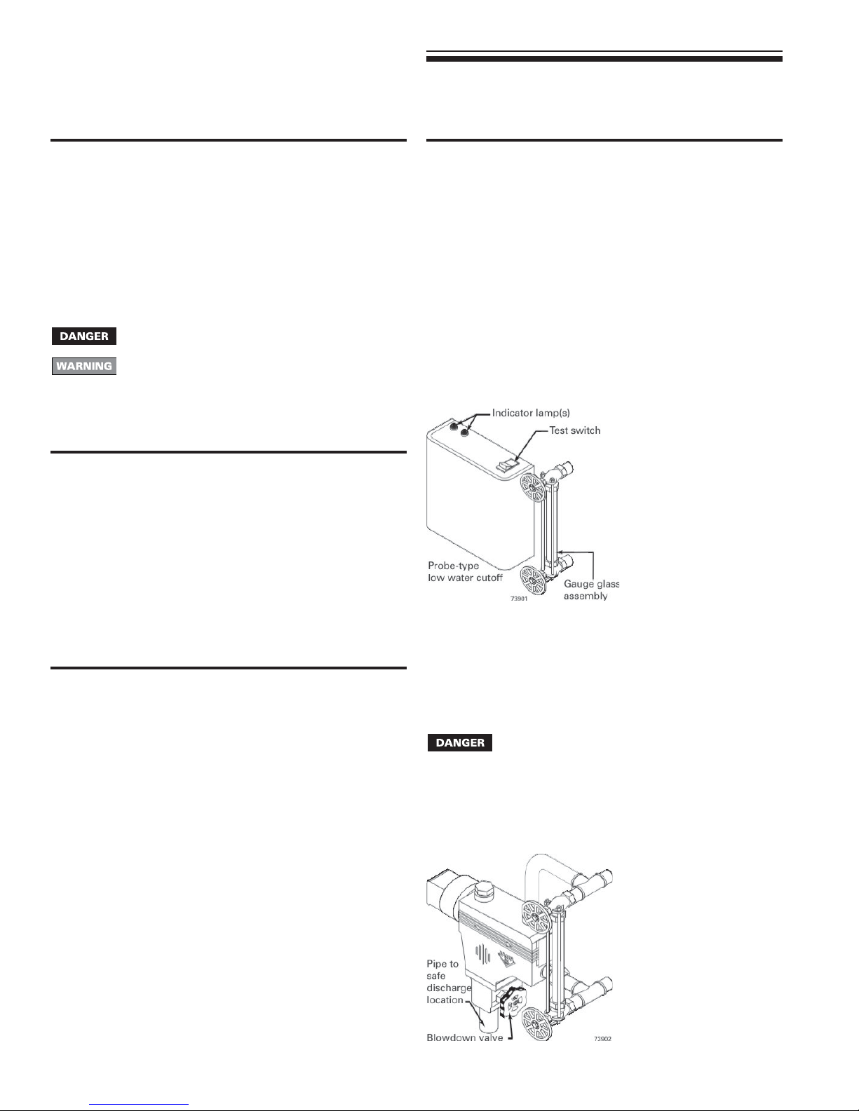
Probe-type low water cutoff (see below)
Clean probe-type low water cutoff for proper operation.
1. Turn off power to boiler and wait 5 minutes.
2. Drain water to bottom of gauge glass.
3. Turn on power.
4. Set thermostat to call for heat. Red neon lamp on lower water
cutoff should light.
5. Wait 5 minutes. Boiler should not fire.
6. Refill boiler to correct waterline. Red lamp should go off.
7. Wait 5 minutes. Boiler should fire.
8. Return thermostat to normal setting.
❏❏
❏ Check/test. . . . . . . . . .
❏❏
Gas piping
1. Sniff near floor and around boiler area for any indication of a
gas leak.
2. Test gas piping using bubble test, per page 12 of this manual, if
there is any indication of a leak.
Boiler waterline
Normal waterline is halfway up gauge glass.
Limit controls
1. Inspect and test the boiler limit control. Verify operation by turning
control set point below boiler pressure. Boiler should cycle off.
Return dial to original setting.
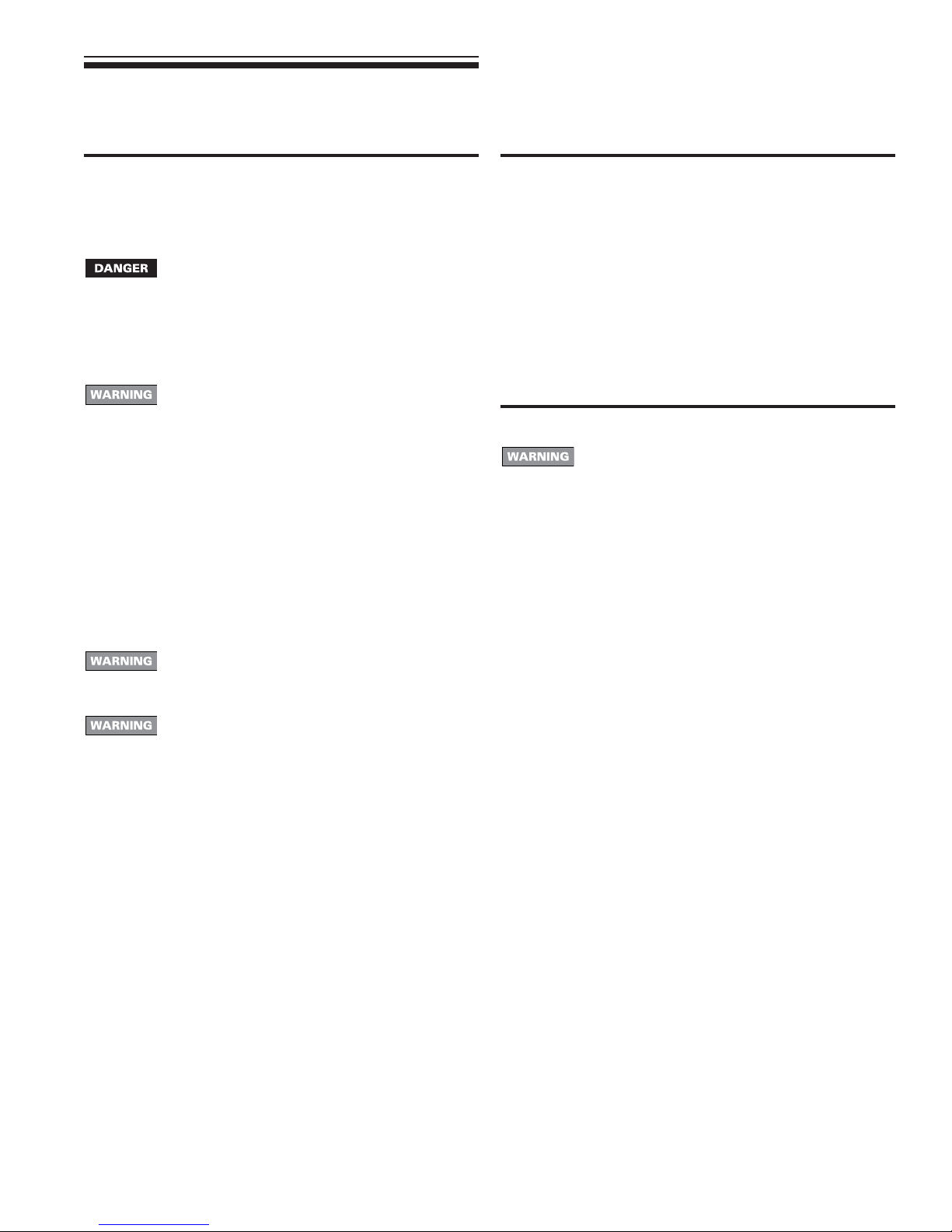
Float-type low water cutoff (when provided by others
— see below)
Clean float-type low water cutoff (when provided by others) to clear
float chamber of sediment.
1. Open blowdown valve at bottom control.
2. Drain water into a bucket.
Scald potential. Boiler pressure must be low to avoid
the potential of severe burns from steam.
3. Check float-type low water cutoff for proper operation:
a. Turn operating control to call for heat.
b. Before water gets hot, drain to bottom of gauge glass. Boiler
should shut off after water level lowers a few inches.
c. Refill boiler to correct waterline. Boiler should come back
on.
22 Part Number 550-110-738/0703
Page 23
GSA
Gas-Fired Steam Boilers – Boiler Manual
11 Service and maintenance continued
❏❏
❏ Check/test. . . . . . . . . .
❏❏
Boiler relief valve
1. After following the warning directions below, if the relief valve
weeps or will not seat properly, replace the relief valve.
Before testing, make certain discharge pipe is properly
connected to valve outlet and arranged to contain
and safely dispose of boiler discharge. Wear gloves
to protect your hands from hot surfaces. Verify that
discharge piping is installed in accordance with this
manual and the instructions on the relief valve tag.
Failure to comply will expose operator and others to
severe personal injury or death.
Safety relief valves should be reinspected AT LEAST
ONCE EVERY THREE YEARS, by a licensed
plumbing contractor or authorized inspection agency,
to ensure that the product has not been affected by
corrosive water conditions and to ensure that the
valve and discharge line have not been altered or
tampered with illegally. Certain naturally occurring
conditions may corrode the valve or its components
over time, rendering the valve inoperative. Such
conditions are not detectable unless the valve and
its components are physically removed and
inspected. This inspection must only be conducted
by a plumbing contractor or authorized inspection
agency — not by the owner. Failure to reinspect the
boiler relief valve as directed could result in unsafe
pressure buildup, which can result in severe personal
injury, death or substantial property damage.
Check the setting of the boiler limit control. The control
should never be set with a pressure above 10 psig.
Operating at a higher pressure can cause damage
to the boiler relief valve.
The boiler relief valve must be tested at least monthly
during the heating season to verify the valve and
discharge piping flow freely. If corrosion and/or
deposits are noticed within the valve body, testing
must be performed more often. A “try lever test” must
also be performed at the end of any non-service
period. Follow the instructions below for a “try lever
test”:
• With the system at operating pressure, lift and hold
the test lever fully open for at least 5 seconds to flush
the valve seat free of sediment and debris. Then
release lever and permit the valve to snap shut.
❏❏
❏ Review with owner
❏❏
1. Review the User’s Information Manual with the owner.
2. Emphasize the need to perform the maintenance schedule
specified in the User’s Information Manual (and in this manual
as well).
3. Remind the owner of the need to call in a licensed contractor
should the boiler or system exhibit any unusual behavior.
4. Remind the owner to follow the proper shutdown procedure
and to schedule an annual start-up at the beginning of the next
heating season.
❏❏
❏ Cleaning boiler heating surfaces
❏❏
The boiler contains ceramic fiber and fiberglass
materials. Use care when handling these materials
per instructions on page 32 of this manual. Failure to
comply could result in severe personal injury.
1. Shut down boiler — Follow “To Turn Off Gas to Appliance”
instructions on boiler and
2. Disconnect breeching and remove damper and draft diverter.
3. Remove upper rear jacket panel. Turn back jacket insulation to
expose collector hood.
4. Remove collector hood. Clean excess boiler cement from
collector hood and cast iron sections.
5. Remove burners from base of boiler. Follow “Burners and base”
on page 21, to thoroughly clean burners. Place newspaper in
base of boiler to collect soot that will fall.
6. With a wire flue brush, clean between the sections.
7. Remove paper and soot. Vacuum or brush base and
surrounding area.
8. Replace collector hood. Seal with boiler cement.
“
Lighting Instructions”.
23Part Number 550-110-738/0703
Page 24
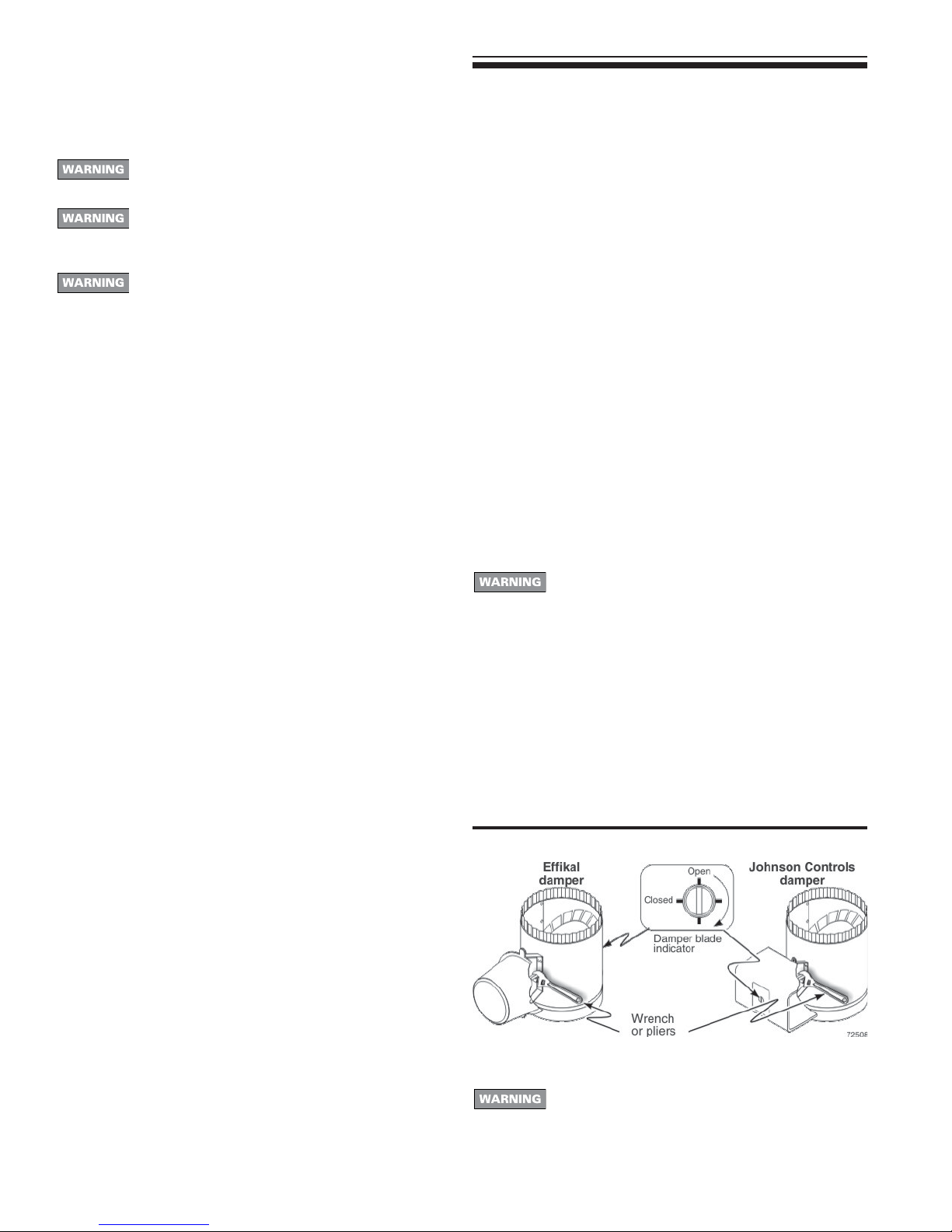
GSA
Gas-Fired Steam Boilers – Boiler Manual
12 Troubleshooting
Label all wires prior to disconnection when servicing
controls. Wiring errors can cause improper and
dangerous operation.
Never jumper (bypass) rollout thermal fuse element
or any other device except for momentary testing as
outlined in “Chart 1”, page 25. Severe personal injury,
death or substantial property damage can result.
Burner base access panel must be in position during
boiler operation to prevent momentary flame rollout
on ignition of main flame. Severe personal injury or
substantial property damage will result.
Before troubleshooting:
1. Have the following items:
a. Voltmeter that can check 120 VAC and 24 VAC.
b. Continuity checker.
c. U-tube manometer.
2. Check for 120 VAC (minimum 102 VAC to maximum 132 VAC)
to boiler.
3. Make sure thermostat is calling for heat and contacts (including
appropriate zone controls) are closed. Check for 24 VAC
between thermostat wire nuts and ground.
In event of vent damper failure:
Effikal vent damper
If troubleshooting chart recommends replacing actuator and actuator
is not immediately available, damper blade can be fixed in an open
position to allow boiler operation. Manually turning blade can cause
actuator damage. Follow these instructions only in case of no heat
or damper actuator malfunction.
1. Move damper service switch to Hold Damper Open position.
Apply call for heat to boiler. Damper blade should then rotate to
Open position and boiler will fire.
2. If step 1 does not open damper, manually rotate damper blade
to open position using wrench or pliers on flat shaft between
damper and actuator. Boiler will fire. Verify that damper service
switch is in Hold Damper Open position. See Figure 15.
3. Do not leave vent damper permanently in this position. Replace
actuator immediately. If vent damper is left in Open position,
boiler will not operate at published efficiencies.
Johnson Controls vent damper
If troubleshooting chart recommends replacing actuator and actuator
is not immediately available, damper blade can be fixed in an open
position to allow boiler operation. Follow these instructions only in
case of no heat or damper actuator malfunction. See Figure 15.
1. Turn off power to boiler.
Failure to turn off power to boiler can result in severe
personal injury, death or substantial property damage.
Troubleshooting sequence:
1. Before proceeding, check for:
• Loose connections, blown fuse or service switch off?
• High limit switch set below boiler water temperature?
• Thermostat set below room temperature?
• Gas not turned on at meter or boiler?
• Incoming gas pressure less than:
5" w.c. for natural gas? 11" w.c. for propane gas?
2. If all of the above check correctly, check gas pressures:
a. With boiler off:
• 13" w.c. maximum natural or propane gas pressure
upstream of gas valve.
b. With boiler on:
• 5" w.c. minimum natural gas pressure or 11" w.c.
propane gas pressure upstream of gas valve.
• 3.5" w.c. minimum natural gas pressure or 10" w.c.
propane gas pressure downstream tapping on gas
valve — Can be adjusted by regulator on gas valve.
c. If gas pressure is incorrect or gas is not available to boiler,
contact gas supplier to correct before proceeding further.
3. Check pilot operation — Follow “Lighting Instructions”, pages
18 and 19.
• If gas is available and you cannot obtain a pilot flame, try
purging the gas line and cleaning pilot and pilot gas tubing.
Follow “Lighting Instructions” again. If you still cannot obtain
a flame, replace pilot burner and gas tubing. If this does not
allow you to obtain a pilot flame, replace gas valve.
• If you obtain a pilot flame, but pilot will not remain on, replace
thermocouple. If this does not correct problem, replace gas
valve and pilot burner.
• If pilot stays on, but main gas will not come on, proceed to
page 25.
2. See vent damper manufacturer’s instructions for procedure to
fix vent damper in open position.
3. Turn on power to boiler.
4. Using wrench or pliers on flat shaft section, manually rotate
damper blade until green light turns on. Boiler will fire. See
Figure 15.
5. Do not leave vent damper permanently in this position. Replace
actuator immediately. If vent damper is left in Open position,
boiler will not operate at published efficiencies.
Figure 15 Manually opening vent damper
Verify proper operation after servicing. • See vent
damper manufacturer’s instructions packed with vent
damper for additional information. Failure to comply
could result in severe personal injury, death or
substantial property damage.
24 Part Number 550-110-738/0703
Page 25
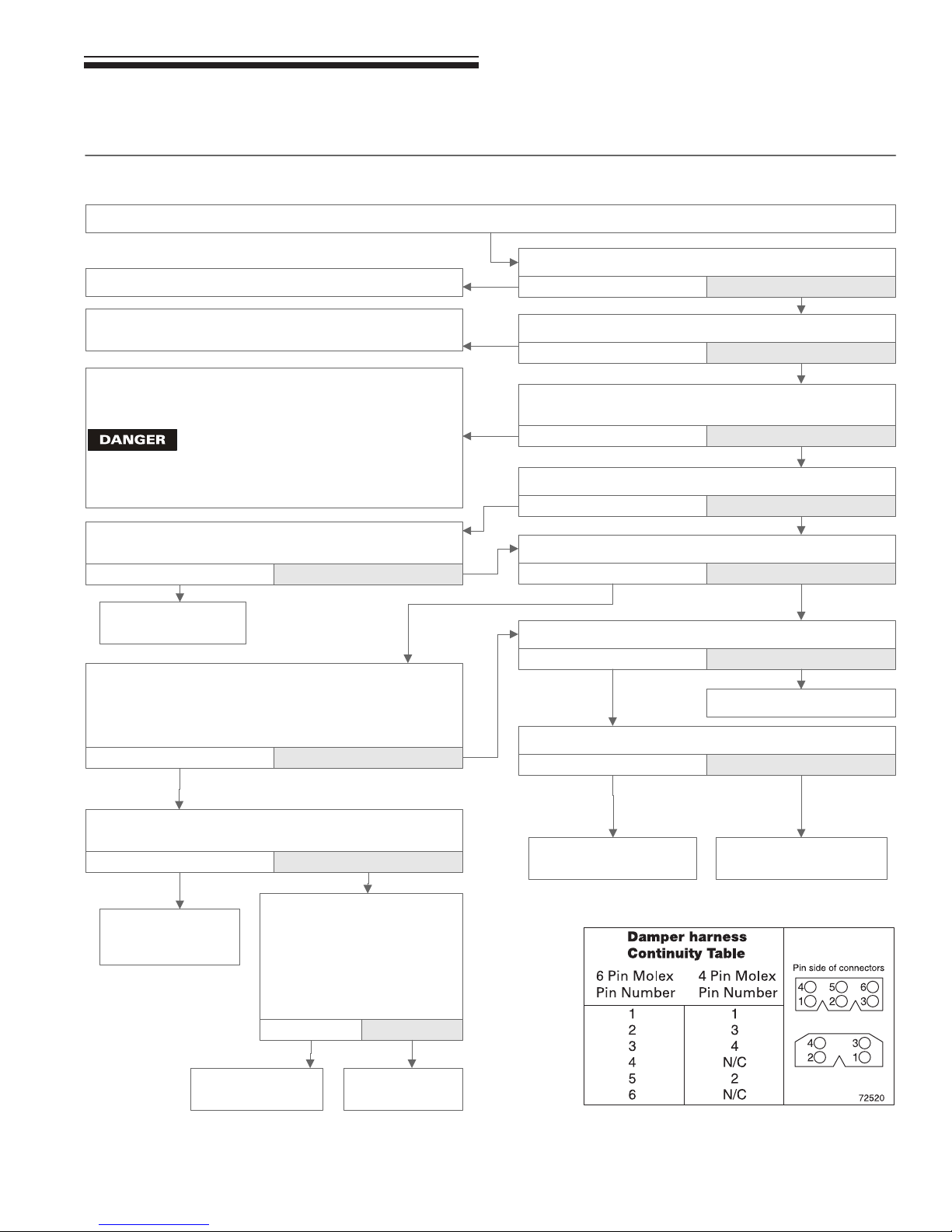
GSA
12 Troubleshooting continued
Chart 1 — Standing pilot — Boiler will not fire
Before proceeding, follow "Troubleshooting sequence" on page 24. If problem persists, then:
Secure connections.
Gas-Fired Steam Boilers – Boiler Manual
Is damper harness securely plugged in at both ends?
No Yes
Check for loose wire connections or bad relay on
transformer.
Check for open thermostat, LWCO, high limit, spill switch or
rollout thermal fuse element contacts or check for loose
wire connections.
If LWCO, spill switch or rollout thermal fuse
element contacts are open, determine cause
and correct condition. Failure to do so will
cause severe personal injury, death or
substantial property damage.
Check/repair out of round stack section. Does vent damper
rotate open?
No Yes
Replace actuator.
Retest.
Open thermostat contacts for 30 seconds. Vent damper will
rotate to closed position. Close thermostat contacts. Vent
damper will rotate to open position. Is 24VAC present
across gas valve terminals?
No Yes
Is 24VAC present across transformer terminals C & Y?
No Yes
Is 24VAC present across transformer terminal C and yellow
wire on vent damper connector?
No Yes
Is vent damper rotated open?
No Yes
Is 24VAC present across gas valve terminals?
No Yes
Is main flame on now?
No Yes
Retest
Is gas valve cock turned to ON position?
No Yes
Check continuity of each wire in damper harness. Does
continuity exist for each wire? See Table right.
No Yes
Replace damper
wiring harness.
Retest.
Replace gas valve.
Retest.
Remove damper harness from
damper harness plug.
TEMPORARILY install jumper
between terminal 2 and
terminal 5 on damper plug in
boiler wiring harness. See
Table, right. Does boiler fire?
No Yes
Replace damper
actuator. Retest.
Turn gas valve cock to
ON position. Retest.
Replace gas valve.
Retest
25Part Number 550-110-738/0703
Page 26
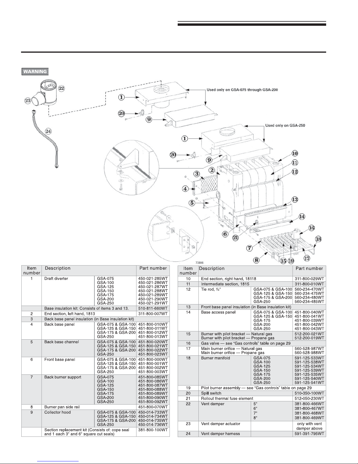
GSA
Gas-Fired Steam Boilers – Boiler Manual
13 Replacement parts
Figure 16 Section assembly, flue collector, draft diverter, vent damper and base assembly
The boiler contains ceramic fiber and fiberglass materials. Use care when handling these materials per instructions on
page 32 of this manual. Failure to comply could result in severe personal injury.
26 Part Number 550-110-738/0703
Page 27
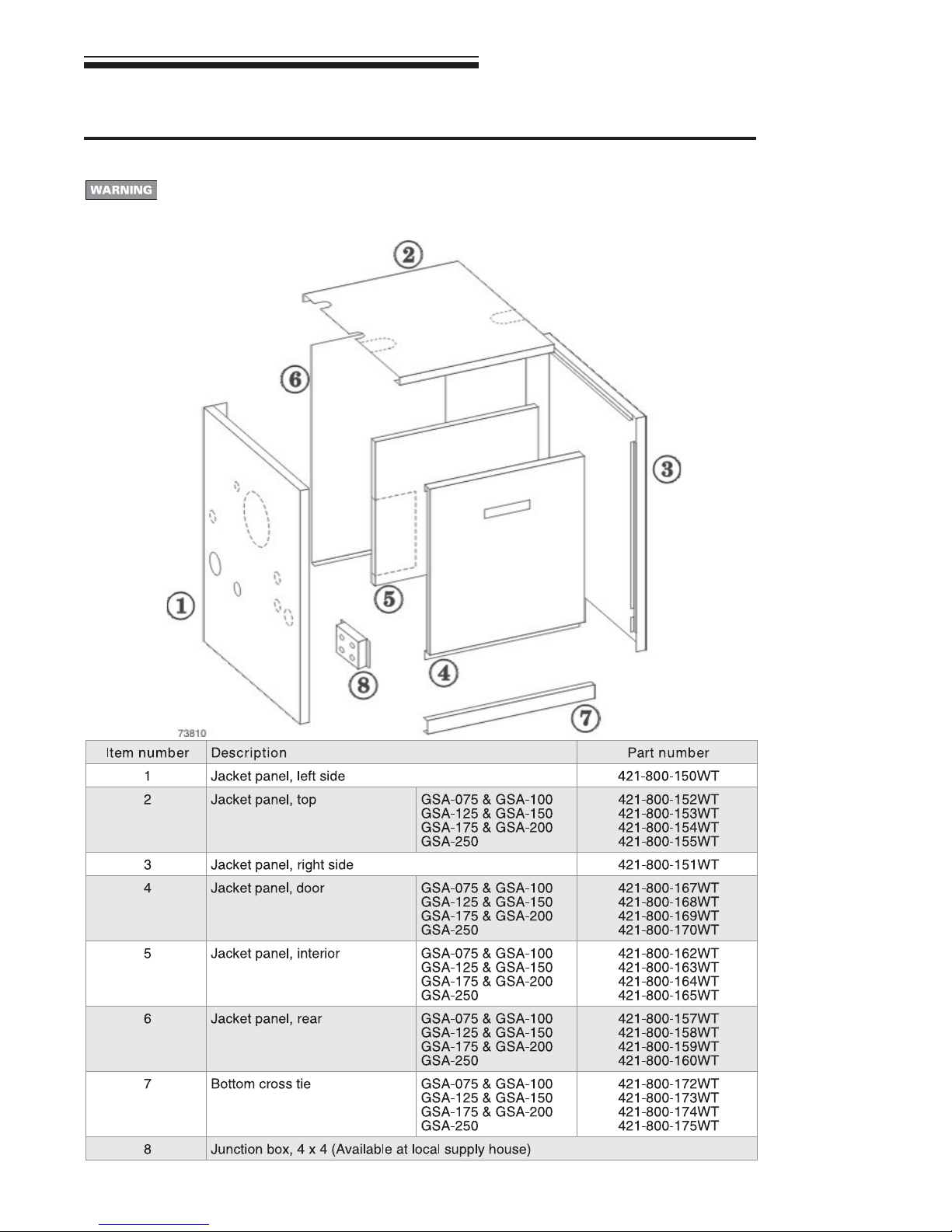
13 Replacement parts continued
Figure 17 Jacket assembly
The boiler contains ceramic fiber and fiberglass materials. Use care when handling these
materials per instructions on page 32 of this manual. Failure to comply could result in severe
personal injury.
GSA
Gas-Fired Steam Boilers – Boiler Manual
27Part Number 550-110-738/0703
Page 28
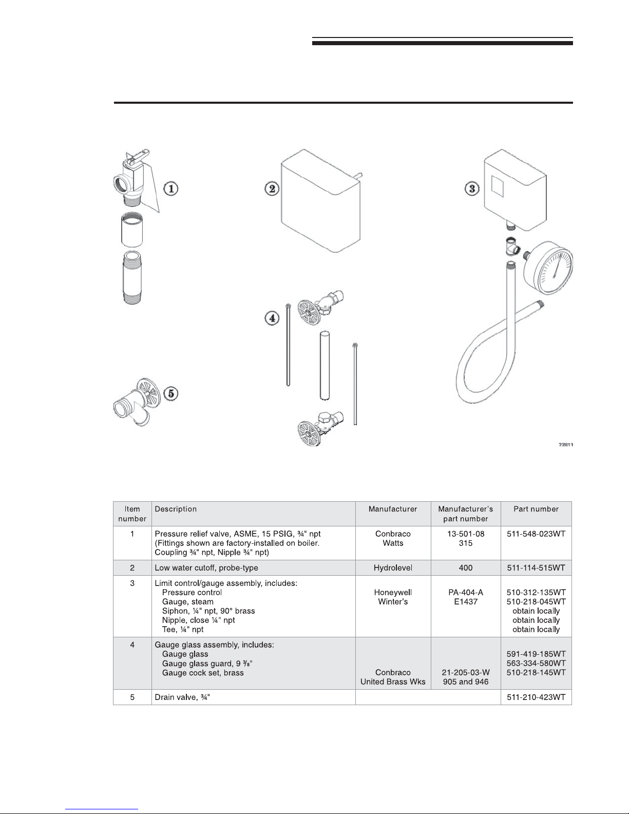
GSA
Gas-Fired Steam Boilers – Boiler Manual
13 Replacement parts continued
Figure 18 Controls and trim
28 Part Number 550-110-738/0703
Page 29
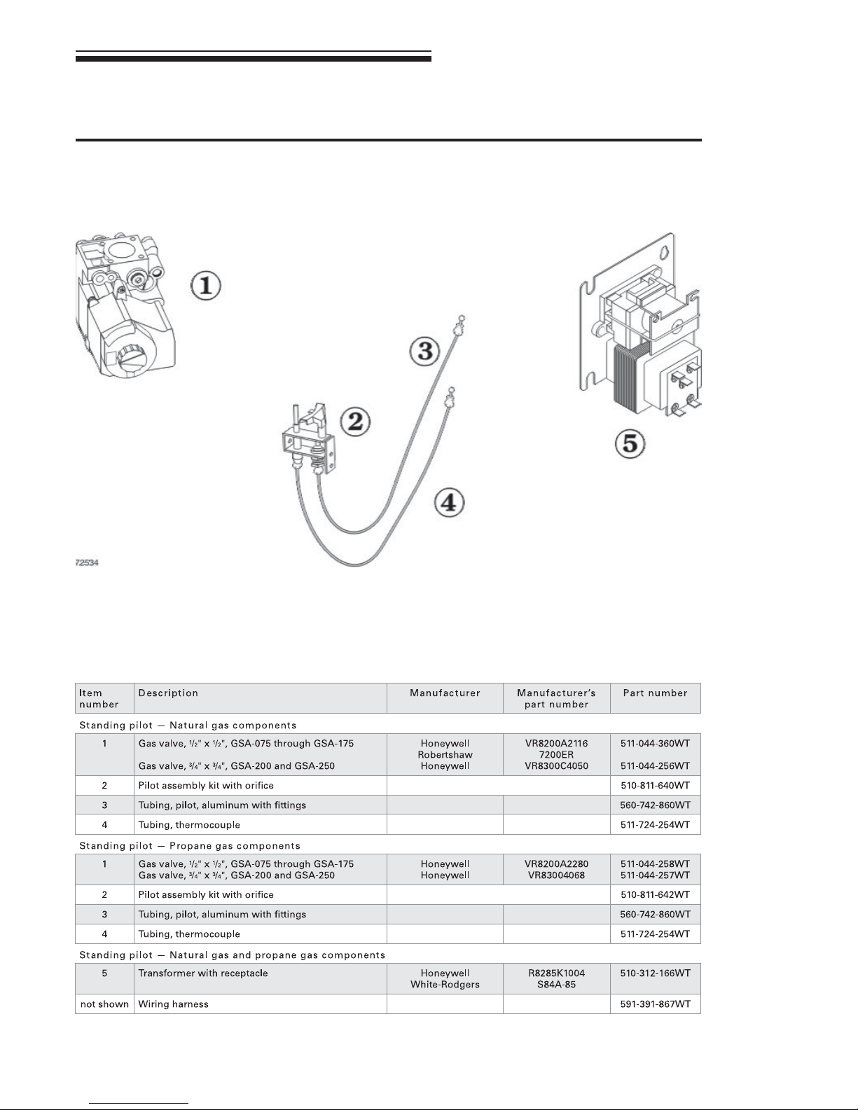
13 Replacement parts continued
Figure 19 Gas controls
GSA
Gas-Fired Steam Boilers – Boiler Manual
29Part Number 550-110-738/0703
Page 30
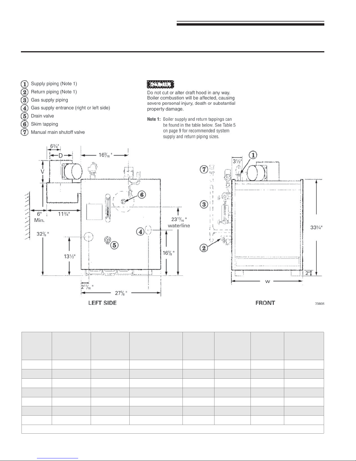
GSA
Gas-Fired Steam Boilers – Boiler Manual
14 Dimensions
Figure 20 Dimensional drawing — ALL DIMENSIONS IN INCHES
Boiler
model
number
Supply
tapping
(inches NPT)
Return
tapping
(inches NPT)
GSA-075 3 2½
GSA-100 3 2½
GSA-125 3 2½
GSA-150 3 2½
GSA-175 3 2½
GSA-200 3 2½
GSA-250 3 2½
Note 2: Size gas piping from meter to boiler per local utility requirements.
30 Part Number 550-110-738/0703
Gas connection
& manifold size
(Note 2)
(inches NPT)
1
/
2
1
/
2
1
/
2
1
/
2
1
/
2
1
/
2
3
/
4
“V”
Damper
height
(inches)
“D”
Vent
diameter
(inches)
“W”
Jacket
width
(inches)
6 5 17 430
6 5 17 430
1
6
/
2
1
6
/
2
6 21¼ 505
6 21¼ 505
9 7 25½ 585
9 7 25½ 585
1
9
/
2
8 29¾ 660
Approximate
shipping
weight
Page 31
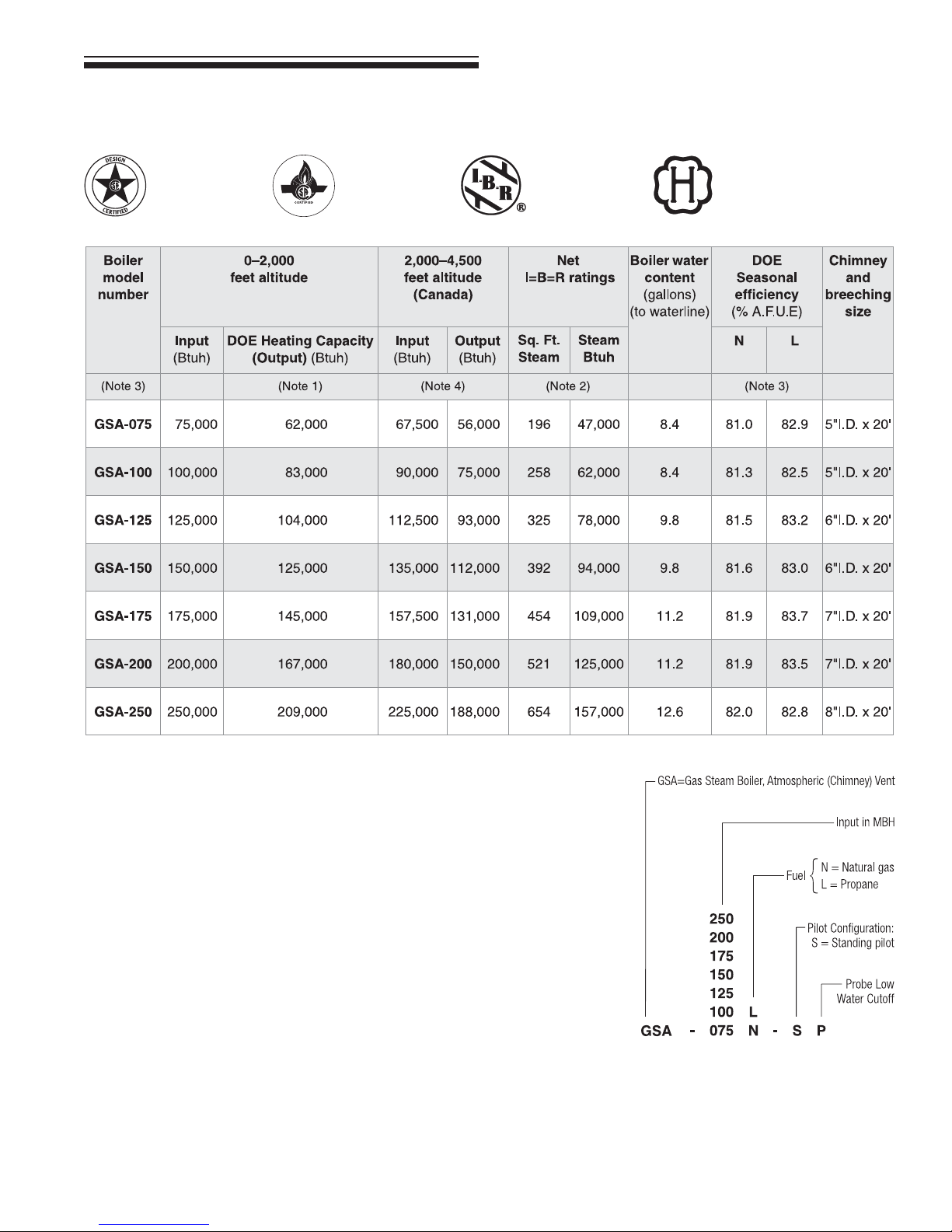
15 Ratings
GSA
Gas-Fired Steam Boilers – Boiler Manual
DOE
Notes
1. Based on standard test procedures prescribed by the United States Department of
Energy.
2. Net I=B=R ratings are based on net installed radiation of sufficient quantity for the
requirements of the building and nothing need be added for normal piping and pickup.
Ratings are based on a piping and pickup allowance of 1.333. An additional allowance
should be made for unusual piping and pickup loads.
3. See information at right for model number suffixes. Letters shown are model number
suffixes. An “N” after the model number designates natural gas. An “L” designates
propane gas.
4. Contact your local dealer regarding information and parts for high altitude applications.
31Part Number 550-110-738/0703
Page 32

GSA
Gas-Fired Steam Boilers – Boiler Manual
Handling ceramic fiber and fiberglass materials
REMOVAL OF COMBUSTION CHAMBER LINING OR BASE PANELS
The combustion chamber lining or base insulation panels in this product contain ceramic fiber materials. Ceramic
fibers can be converted to cristobalite in very high temperature applications. The International Agency for Research
on Cancer (IARC) has concluded, "Crystalline silica inhaled in the form of quartz or cristobalite from occupational
sources is carcinogenic to humans (Group 1).":
■ Avoid breathing dust and contact with skin and eyes.
• Use NIOSH certified dust respirator (N95). This type of respirator is based on the OSHA requirements for
cristobalite at the time this document was written. Other types of respirators may be needed depending on
the job site conditions. Current NIOSH recommendations can be found on the NIOSH web site at
www.cdc.gov/niosh/homepage.html.
also listed on this web site.
• Wear long-sleeved, loose fitting clothing, gloves, and eye protection.
■ Apply enough water to the combustion chamber lining or base insulation to prevent airborne dust.
■ Remove combustion chamber lining or base insulation from the boiler and place it in a plastic bag for disposal.
■ Wash potentially contaminated clothes separately from other clothing. Rinse clothes washer thoroughly.
NIOSH stated First Aid.
■ Eye: Irrigate immediately
■ Breathing: Fresh air.
NIOSH approved respirators, manufacturers, and phone numbers are
http://
REMOVAL OF FIBERGLASS WOOL — OR —
INSTALLATION OF FIBERGLASS WOOL, COMBUSTION CHAMBER LINING OR BASE
PANELS:
This product contains fiberglass jacket insulation and ceramic fiber materials in combustion chamber lining or base
panels in gas fired products. Airborne fibers from these materials have been listed by the State of California as a
possible cause of cancer through inhalation.
■ Avoid breathing dust and contact with skin and eyes.
• Use NIOSH certified dust respirator (N95). This type of respirator is based on the OSHA requirements for
fiberglass wool at the time this document was written. Other types of respirators may be needed depending
on the job site conditions. Current NIOSH recommendations can be found on the NIOSH web site at
www.cdc.gov/niosh/homepage.html
also listed on this web site.
• Wear long-sleeved, loose fitting clothing, gloves, and eye protection.
■ Operations such as sawing, blowing, tear out, and spraying may generate airborne fiber concentration requiring
additional protection.
■ Wash potentially contaminated clothes separately from other clothing. Rinse clothes washer thoroughly.
NIOSH stated First Aid.
■ Eye: Irrigate immediately
■ Breathing: Fresh air.
. NIOSH approved respirators, manufacturers, and phone numbers are
http://
32 Part Number 550-110-738/0703
W-T
8201 W. Calumet Rd.
Milwaukee, WI 53223
 Loading...