

User Manual
www.GlobalTestSupply.com
CT4076

Safety Summary
To avoid personal injury and/or product damage, review and
comply with the following safety precautions. These precautions
apply to both operating and maintenance personnel and must be
followed during all phases of operation, service, and repair of this
instrument.
Only qualied personnel should use this probe. This differential
voltage probe is designed to be used by personnel who are
trained, experienced, or otherwise qualied to recognize
hazardous situations and who are trained in the safety
precautions necessary to avoid possible injury when using such a
device.
This instrument is intended for usage within Measurement
Category I (CAT I) only.
Do not work alone when working with high voltages.
For your own safety, inspect the probe and accessories for
cracks and frayed or broken leads before each use. If defects are
noted, DO NOT USE the probe.
Hands, shoes, oor and work bench must be dry.
Avoid making measurements under humidity, dampness or other
environmental conditions that might affect safety.
The probe should be kept clean and free of any conductive
contamination.
Do not remove the probe casing. Removal of the probe’s casing
may expose you to electric shock.
Do not use the probe with its case open.
Disconnect the inputs and outputs of the probe before opening
the case.
www.GlobalTestSupply.com

Use only in ofce-type indoor setting
The instrument is designed to be used in ofce-type indoor
environments. Do not operate the instrument:
z
In the presence of noxious, corrosive, or flammable
fumes, gases, vapors, chemicals, or finely-divided
particulates.
z
In environments where there is a danger of any liquid
being spilled on the instrument.
z
In air temperatures exceeding the specified operating
temperatures.
z
In atmospheric pressures outside the specified altitude
limits or where the surrounding gas is not air.
Not for critical applications.
This instrument is not authorized for use in contact with the
human body or for use as a component in a life-support device or
system.
Hazardous voltages may be present in unexpected locations in
circuitry being tested when a fault condition in the circuit exists.
Do not substitute parts that are not approved by Cal Test
Electronics or modify this instrument. Return the instrument to
Cal Test Electronics for service and repair to ensure that safety
and performance features are maintained.
A WARNING statement calls attention to an operating procedure,
practice, or condition, which, if not followed correctly, could result
in injury or death to personnel.
A CAUTION statement calls attention to an operating procedure,
practice, or condition, which, if not followed correctly, could result
in damage to or destruction of parts or the entire product.
www.GlobalTestSupply.com

© 2015 All rights reserved.
ELDITEST is a trademark of Sefram Instruments and Systems
and is licensed for use by Cal Test Electronics.
ELDITEST products are covered by US and foreign patents,
issued and pending. Information is this publication supersedes all
earlier versions. Specications subject to change without notice.
For product information, sales, service, and technical support:
Call: 1-800-572-1028 or visit: caltestelectronics.com
Compliance Statements
Disposal of Old Electrical& Electronic Equipment
(Applicable in the European Union and other
European countries with separate collection
systems). This product is subject to Directive
2012/19/EU of the European Parliament and the
Council of the European Union on waste
electrical and electronic equipment (WEEE), and
in jurisdictions adopting that Directive, is marked
as being put on the market after August 13, 2005,
and should not be disposed of as unsorted
municipal waste. Please utilize your local WEEE
collection facilities in the disposition of this product and otherwise
observe all applicable requirements.
800-572-1028 caltestelectronics.com 3
www.GlobalTestSupply.com

Table of Contents Page
1 Introduction .............................................................5
1. Overview ...................................................................................5
2. Features ....................................................................................5
3. Initial Inspection ........................................................................5
2 Product Description ..................................................6
1. Front Panel ................................................................................6
3 Using the Probe ........................................................6
1. Getting Started ..........................................................................6
2. Vertical Scale on Oscilloscope ......................................................7
3. External Power Source ................................................................7
4. Using a DMM .............................................................................7
4 Specications ...........................................................8
5 Cleaning ...................................................................9
6 VoltageDeratingCurve ............................................9
7 Service&WarrantyInformation ............................10
1. Limited One-Year Warranty .......................................................10
2. Calibration and Repair ..............................................................10
800-572-1028 caltestelectronics.com 4
www.GlobalTestSupply.com

1 Introduction
1. Overview
Use the CT4076 35-MHz differential probe to make safe and
accurate oating measurements with an oscilloscope. The
CT4076 differential probe allows conventional earth-grounded
oscilloscopes to be used for oating signal measurements of up
to ±7.5 kV for both differential and common mode voltage.
2. Features
z
35 MHz bandwidth
z
Selectable attenuation settings of 100x or 1000x
z
Up to ±7.5 kV differential and common mode voltage
z
Compatible with most oscilloscopes
z
Powered by included 9 VDC mains adapter
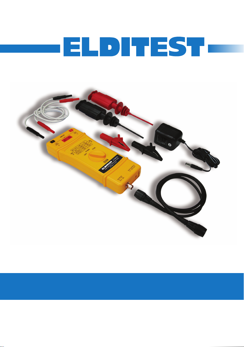
3. Initial Inspection
This unit is tested prior to shipment. It is therefore ready for
immediate use upon receipt. An initial physical inspection
should be made to ensure that no damage has been sustained
during shipment. After the inspection, verify the contents of the
shipment. The included accessories for this product are:
z
Two fully insulated pincer style clips (black & red)
z
Two fully insulated alligator clips (black & red)
z
Two 60 cm input leads (black & red)
z
One 100 cm insulated BNC output cable
z
One 9 V mains adapter
z
User manual
800-572-1028 caltestelectronics.com 5
www.GlobalTestSupply.com

2 Product Description
1. Front Panel
44 mm Input
Safety Banana
Jacks
Power On/Off Indicator
(Green)
Output BNC Connection
Overload Indicator (Red)
Attenuation Function Switch
External Power
Connection
Figure 1. Front Panel
3 Using the Probe
1. Getting Started
1. Connect the leads to the inputs on the probe.
2. Connect the clips to the leads.
3. Connect the probe to the oscilloscope with the BNC
cable.
4. Connect the probe to the mains adapter.
5. Switch the probe from “OFF” to the desired attenuation
800-572-1028 caltestelectronics.com 6
www.GlobalTestSupply.com

ratio. The power light should come on.
6. Connect the clips to the circuit to be tested.
2. Vertical Scale on Oscilloscope
The actual vertical scale of the oscilloscope is equal to the
attenuation factor multiplied by the range of vertical scale
selected on the oscilloscope. For example, with the probe on
factor 100x, the oscilloscope on 0.5 V/div, the real vertical scale
is 100 x 0.5 = 50 V/div. With the probe on 1000x, the real vertical
scale is 1000 x 0.5 = 500 V/div. These values apply when the
oscilloscope is set to 50 Ω input. When the oscilloscope is set to
1 MΩ input, the actual vertical scale will be halved: 25 V/div for
the 100x probe setting and 250 V/div for the 1000x probe setting.
See the chart below.
Vertical Scale on Oscilloscope
Probe
Output
Impedance
50 Ω 50 Ω 100x 0.5 V/div 50 V/div
50 Ω 50 Ω 1000x 0.5 V/div 500 V/div
50 Ω 1 MΩ 100x 0.5 V/div 25 V/div
50 Ω 1 MΩ 1000x 0.5 V/div 250 V/div
Scope Input
Impedance
Probe
Attenuation
Setting
Vertical Scale
Reading on the
Oscilloscope
Actual Vertical Scale
of the Oscilloscope
3. External Power Source
Power consumption of the probe is about 200 mA, thus it is
not suited for battery usage. Use the supplied adapter only.
CAUTION: The probe may be damaged when the input power
exceeds 12 VDC.
4. Using a DMM
Using a DMM rather than an oscilloscope can signicantly
increase your accuracy. Use the CT2944-50 plus the CT3956
converter to use the probe with a DMM.
800-572-1028 caltestelectronics.com 7
www.GlobalTestSupply.com

4 Specications
All specications apply to the unit after a temperature stabilization time of 15 minutes over an
ambient temperature range of 25 °C ± 5 °C.
CT4076 Specications
Operating Parameters
Bandwidth 35 MHz
Rise Time 10 ns
Attenuation 100x / 1000x
Accuracy ±2%
AC CMRR -80 dB @ 60 Hz
Input Impedance Between inputs: 50 MΩ // 1.3 pF
Input Voltage
Differential Voltage (DC+ACpk) ±750 V / ±7.5 kV
Common-Mode Voltage (DC+ACpk) ±7.5 kV or 5.5 kVrms
Absolute Max Voltage (DC+ACpk) ±7.5 kV or 5.5 kVrms
Output Voltage
Swing ±8 V (±4 V into 50 Ω load)
Source Impedance 50 Ω
General
Power Supply External 9 VDC power supply
Power Consumption 200 mA about (9 VDC)
Operating Temperature/Humidity 0°C to 50°C / 10% to 85% RH
Storage Temperature/Humidity -30°C to 70°C / 10% to 90% RH
Cable Length 100 cm
Input Leads Length 60 cm each
Weight 350 g
Dimensions 220 x 85 x 30 mm
-60 dB @ 100 Hz
-50 dB @ 1 MHz
Each input to ground: 25 MΩ // 2.6 pF
Specications are subject to change without notice. To ensure the most current version of this
manual, please download the current version from our website: caltestelectronics.com.
800-572-1028 caltestelectronics.com 8
www.GlobalTestSupply.com

5 Cleaning
This probe does not require any particular cleaning. If necessary,
clean the case with a cloth slightly moistened with soapy water
WARNING
Dry the probe thoroughly before attempting to make voltage
measurements.
CAUTION
Do not subject the probe to solvents or solvent fumes as these
can cause deterioration of the probe body and cables.
6 Voltage Derating Curve
The derating curve of the absolute maximum input voltage in
common mode is show as follows:
Figure 2. CT4076 Derating Curve
800-572-1028 caltestelectronics.com 9
www.GlobalTestSupply.com

7 Service & Warranty Information
1. Limited One-Year Warranty
Cal Test Electronics warrants this product to be free from
defective material or workmanship for a period of 1 year from
the date of original purchase. Under this warranty, Cal Test
Electronics is limited to repairing the defective device when
returned to the factory, shipping charges prepaid, within the
warranty period.
Units returned to Cal Test Electronics that have been subject to
abuse, misuse, damage or accident, or have been connected,
installed or adjusted contrary to the instructions furnished by Cal
Test Electronics, or that have been repaired by unauthorized
persons, will not be covered by this warranty.
Cal Test Electronics reserves the right to discontinue models,
change specications, price, or design of this device at any time
without notice and without incurring any obligation whatsoever.
The purchaser agrees to assume all liabilities for any damages
and/or bodily injury which may result from the use or misuse of
this device by the purchaser, his employees, or agents.
This warranty is in lieu of all other representations or warranties
expressed or implied and no agent or representative of Cal
Test Electronics is authorized to assume any other obligation in
connection with the sale and purchase of this device.
2. Calibration and Repair
If you have a need for any calibration or repair services, please
visit us on the web at: caltestelectronics.com. See “Support.”
(A Cal Test Electronics Brand)
800-572-1028 or 714-221-9330
800-572-1028 caltestelectronics.com 10
www.GlobalTestSupply.com
ELDITEST
22820 Savi Ranch Parkway
Yorba Linda, CA 92887
caltestelectronics.com

Prescriptions de sécurité
An d’éviter les blessures et une détérioration du produit,
examiner et conformez-vous aux précautions de sécurité cidessous. Ces précautions s’appliquent au personnel qui utilise et
qui répare et doivent être scrupuleusement suivies.
Seul un personnel qualié peut utiliser cette sonde. Cette sonde
différentielle est conçue pour être utilisé par des personnes
formées et capable d’identier les situations potentiellement
dangereuses et qui comprennent ces prescriptions de sécurité ;
ainsi ils éviteront tout risque de blessure dans l’utilisation de cette
sonde.
Cet instrument est conçu pour mesurer des tensions de
Catégorie I (CAT I).
Ne travailler pas seul lorsque vous travaillez sur des tensions
élevées.
Pour votre sécurité, inspectez la sonde et ses accessoires avant
chaque utilisation et vériez l’absence de coupures, cassures ou
craquelures. Si un ou des défauts sont constatés, ne pas utiliser
la sonde.
Les mains, les chaussures, le sol et la paillasse de travail doivent
être parfaitement secs.
Ne jamais effectuer des mesures dans des conditions d’humidité
trop élevées qui pourraient compromettre votre sécurité
La sonde doit être propre et le boitier maintenu sans traces de
contaminants qui pourraient être conducteurs.
Ne pas ouvrir le boitier. Vous pourriez être exposé à des risques
de choc électrique.
Ne jamais utiliser la sonde boitier ouvert.
Débranchez impérativement les cordons avant d’ouvrir le boitier..
800-572-1028 caltestelectronics.com 21
www.GlobalTestSupply.com

Utilisation à l’intérieur uniquement
Cette sonde est conçue pour être utilisée à l’intérieur dans un
environnement de type bureau. Ne pas utiliser l’instrument dans
les cas suivants:
z
En présence de gaz toxiques, corrosifs, inflammables ou
de poussières fines.
z
En cas de risque de projection d’un liquide sur la sonde.
z
Dans des conditions environnementales hors du
domaine spécifié.
z
En dehors des limites de pression et d’altitude spécifiées.
Ne pas utiliser pour les applications dites critiques.
Cet instrument n’est pas autorisé pour l’utilisation en contact
avec le corps humain ou en tant que composant d’un appareil ou
système d’assistance vitale ou de survie.
Des tensions élevées peuvent être présentes dans le cas de
mesure sur un circuit présentant une condition de défaut.
Ne remplacez pas des composants ou des parties qui ne sont
pas approuvées par Cal Test Electronics et ne modiez pas cet
instrument. Renvoyez l’instrument à Cal Test Electronics pour
la maintenance et la réparation an de vous assurer que la
sécurité, les fonctionnalités, les spécications sont maintenues
Un signe DANGER attire l’attention sur une procédure de
fonctionnement, une pratique, ou une condition, qui, si elle n’est
pas suivie correctement, peut causer une blessure ou entraîner
la mort de l’utilisateur.
Un signe ATTENTION attire l’attention sur une procédure de
fonctionnement, une pratique, ou une condition, qui, si elle n’est
pas suivie correctement, peut causer des dégâts ou détruire des
parties du produit ou le produit complet.
800-572-1028 caltestelectronics.com 22
www.GlobalTestSupply.com

© 2015 Tous droits réservés.
ELDITEST est une marque déposée de Sefram. Cal Test
Electronics dispose des droits d’utilisation de la marque.
Les produits ELDITEST peuvent être sujets à des brevets
déposés ou en cours, au sens des lois américaines. Les
spécications peuvent être modiées sans préavis.
Pour les informations les plus récentes vous pouvez contacter
CALTEST. Par téléphone: 1-800-572-1028 ou visiter www.
caltestelectronics.com
Déclarations de conformité
DEEE
Ce produit est règlementé par la Directive
2002/96/CE du parlement européen et du Conseil
de l’Union européenne sur les déchets
d’équipement électriques et électroniques, et
pour les pays ayant adopté cette Directive, il est
signalé comme étant placé sur le marché après
le 13 août 2005 et ne doit pas être éliminé
comme un déchet non trié. Pour vous
débarrasser de ce produit, veuillez faire appel à
une société de collecte des DEEE et observer
toutes les obligations en vigueur.
800-572-1028 caltestelectronics.com 23
www.GlobalTestSupply.com

Sommaire
15 Introduction ...........................................................26
1. Généralités ..............................................................................26
2. Caractéristiques principales .......................................................26
3. Contrôle de votre produit ..........................................................26
16 Description du produit ...........................................27
1. Face avant ...............................................................................27
17 Miseenœuvre ........................................................28
1. Pour réaliser une mesure .........................................................28
2. Réglage de l’échelle verticale de l’oscilloscope ............................28
18 Spécications .........................................................30
19 Nettoyage ...............................................................31
20 Courbetension/fréquence ....................................31
21 Maintenance&garantie .........................................32
1. Garantie limitée de 1 an ............................................................32
2. Ajustage et réparation ..............................................................32
800-572-1028 caltestelectronics.com 24
www.GlobalTestSupply.com

15 Introduction
1. Généralités
La sonde différentielle CT4076 35-MHz permet d’effectuer des
mesures sur des tensions élevées, avec un oscilloscope, et selon
une technique différentielle ottante. La sonde CT4076 permet
à un oscilloscope relié à la terre d’effectuer des mesures sur
un signal pouvant aller jusqu’à ±7.5 kV (tension différentielle ou
tension de mode commun).
2. Caractéristiques principales
z
Bande passante : 35 MHz
z
Atténuation : 100x ou 1000x
z
Tension maximale : ±7.5 kV (différentielle ou de mode
commun)
z
Compatible avec une majorité d’oscilloscopes
z
Alimentation par adaptateur secteur 9 VDC (fourni)
3. Contrôle de votre produit
Votre sonde a été contrôlée avant expédition et est prête à être
utilisée. Une vérication est recommandée pour s’assurer qu’il
n’y a pas eu de dégât occasionné par le transport. Après cette
vérication, assurez-vous que l’ensemble des accessoires est
présent dans la boite:
z
2 grippe-fils de sécurité (noir & rouge)
z
2 pinces crocodiles de sécurité (noir & rouge)
z
2 cordons de 60 cm (noir & rouge)
z
Un câble BNC isolé de 100 cm
z
Un adaptateur secteur 9 V
z
Manuel d’utilisation
800-572-1028 caltestelectronics.com 25
www.GlobalTestSupply.com

16 Description du produit
1. Face avant
Bornes d’entrée
4mm
Indication On/Off (vert)
Figure 1. F ace Avan t
LED dépassement
(Rouge)
Commutateur
d’atténuation
Entrée adaptateur
secteur
Sortie BNC
(vers oscilloscope)
17 Mise en œuvre
1. Pour réaliser une mesure
1. Branchez les cordons à la sonde.
2. Branchez le grippe-l ou les pinces crocodiles sur les
cordons
3. Branchez la sonde à l’oscilloscope à l’aide du câble
BNC.
4. Branchez la sonde à l’adaptateur secteur
800-572-1028 caltestelectronics.com 26
www.GlobalTestSupply.com

5. Tournez le commutateur rotatif de “OFF” à l’atténuation
désirée. ratio. La sonde se met en marche.
6. Branchez la sonde au dispositif à mesurer (grippe-l ou
pinces crocodiles).
2. Réglage de l’échelle verticale de l’oscilloscope
La valeur effective de l’échelle verticale de l’oscilloscope est égale au facteur
d’atténuation de la sonde multiplié par l’échelle verticale (le calibre) de
l’oscilloscope. Ainsi, si la sonde est en atténuation de 100x, si l’oscilloscope
est sur 0.5 V/div, l’échelle verticale réelle sera de100 x 0.5 = 50 V/div. Avec
une atténuation de 1000x, l’échelle réelle serait de 1000 x 0.5 = 500 V/div.
Cette règle s’applique pour un oscilloscope ayant une entrée 50 Ω input.
Pour un oscilloscope ayant une impédance d’entrée de 1 MΩ, l’échelle
verticale serait de: 25 V/div pour l’atténuation de 100x et 250 V/div pour une
atténuation de 1000. Voir tableau ci-dessous.
Echelle verticale sur l’oscilloscope
Impédance de
sortie (sonde)
50 Ω 50 Ω 100x 0.5 V/div 50 V/div
50 Ω 50 Ω 1000x 0.5 V/div 500 V/div
50 Ω 1 MΩ 100x 0.5 V/div 25 V/div
50 Ω 1 MΩ 1000x 0.5 V/div 250 V/div
Impédance
d’entrée de
l’oscilloscope
Atténuation
(sonde)
Echelle
verticale de
l’oscilloscope
Echelle réelle
en tenant
compte de
l’atténuation
3. Adaptateur secteur
La consommation de la sonde est d’environ 200 mA. Il ne faut utiliser que
l’adaptateur secteur fourni. ATTENTION: la sonde pourrait être endommagée
si une tension supérieure à 12V DC était appliquée sur la prise d’entrée 9V. (la
garantie de la sonde serait annulée)
4. Utilisation avec un multimètre
L’utilisation d’un multimètre à la place d’un oscilloscope améliore la précision.
Pour cela, il faut avoir l’adaptateur CT2944-50 et le convertisseur CT3956
pour une utilisation correcte et précise avec un multimètre.
800-572-1028 caltestelectronics.com 27
www.GlobalTestSupply.com

18 Spécications
Toutes les spécications sont données après un temps de chauffe de 15 minutes et dans un
environnement à 25 °C ± 5 °C.
Spécications - CT4076
Fonctionnement
Bande passante 35 MHz
Temps de montée 10 ns
Atténuation 10x/100x
Précision ±2%
Réjection de mode commun (CMRR) -80 dB @ 60 Hz
Impédance d’entée Entre les 2 entées : 50 MΩ // 1.3 pF
Tension d’entrée
Tension maximale différentielle admissible
(DC+ACcrête)
Tension maximale de mode commun
(DC+ACcrête)
Tension maximale admissible (DC+ACcrête) ±7.5 kV or 5.5 kVrms
Tension de sortie
Tension maximale 8 V dans 1 MΩ ou 4 V dans 50 Ω
Impédance de sortie 50 Ω
Spécications générales
Alimentation Adaptateur secteur fournissant 9V DC
Consommation Environ 200 mA (sous 9 VDC)
Température de fonctionnement 0°C à 50°C / 10% à 85% HR
Température de stockage -30°C à 70°C / 10% à 90% HR
Longueur du câble BNC 100 cm
Longueur des cordons 60 cm
Masse 350 g
Dimensions 220 x 85 x 30 mm
-60 dB @ 100 Hz
-50 dB @ 1 MHz
Entre l’entrée et la terre : 25 MΩ // 2.6 pF
±750 V / ±7.5 kV
±7.5 kV or 5.5 kVrms
Les spécications peuvent être modiées sans préavis. Pour avoir la dernière version de ce
manuel, merci de vous rendre sur le site web: caltestelectronics.com.
800-572-1028 caltestelectronics.com 28
www.GlobalTestSupply.com

19 Nettoyage
Vériez périodiquement l’état de propreté de votre sonde. Si
besoin, nettoyez le corps de sonde avec un chiffon doux et
humide.
DANGER
Toujours vérier que la sonde est parfaitement dèche avant de
l’utiliser.
ATTENTION
Ne jamais utiliser de solvant ou exposer la sonde ou ses
accessoires à des vapeurs de solvants. Risque d’endommager
votre sonde.
20 Courbe tension/ fréquence
En fonction de la fréquence, la tension maximale donnée par la
courbe ci-dessous est à respecter scrupuleusement:
Tension (Vp-p)
Fréquence (MHz)
Figure 2. Courbe Tension/ Fréquence
800-572-1028 caltestelectronics.com 29
www.GlobalTestSupply.com

21 Maintenance & garantie
1. Garantie limitée de 1 an
Cal Test Electronics garantit cette sonde 1 an à partir de sa date
d’achat. La responsabilité de Cal Test Electronics se limite à
réparer le produit défectueux retourné à l’usine, frais de retour
prépayés pendant la période de garantie.
Les produits retournés à Cal Test Electronics qui auraient fait
l’objet d’une mauvaise utilisation, d’erreur de manipulation, de
chocs ou utilisés dans un domaine autre que celui spécié dans
ce manuel ne sont pas couverts par la garantie. Il en est de
même si le produit a été ouvert ou réparé au préalable par du
personnel non habilité.
Cal Test Electronics se réserve le droit d’arrêter la
commercialisation de ce produit sans préavis et sans qu’aucune
compensation ne puisse être demandée.
L’acheteur accepte de prendre à sa charge toutes les
conséquences liées à l’utilisation de cette sonde, quelles qu’en
soient les causes ou les conséquences, et quelle que soit la
personne qui utilise la sonde.
Cette garantie limitée se substitue à toute autre forme de
garantie. Cal Test Electronics n’assume aucune autre forme de
responsabilité liée au produit ou à son utilisation.
2. Ajustage et réparation
Si vous devez ajuster ou réparer votre sonde, merci de visiter
notre site: caltestelectronics.com. Consulter “Support.”
800-572-1028 caltestelectronics.com 30
www.GlobalTestSupply.com
 Loading...