

CT4024
User Manual

Safety Summary
WARNING CAUTION
To avoid personal injury and/or product damage, review and comply
with the following safety precautions. These precautions apply to both
operating and maintenance personnel and must be followed during all
phases of operation, service, and repair of this instrument.
Only qualied personnel should use this probe. This high voltage
probe is designed to be used by personnel who are trained, experienced,
or otherwise qualied to recognize hazardous situations and who are
trained in the safety precautions necessary to avoid possible injury when
using such a device.
This instrument is intended for usage within Measurement Category I
(CAT I) only.
Do not exceed 60 seconds of contact with high voltage. When
making contact between this probe and any circuit with voltages ≥8 kV
DC, ≥5 kVrms AC, or ≥15 kVpk-pk AC, wait for 5 minutes between such
measurements.
Do not work alone when working with high voltages.
Do not apply to the input any potential that exceeds the maximum
rating of the probe.
For your own safety, inspect the probes for cracks and frayed or broken
leads before each use. If defects are noted, DO NOT USE the probe.
Hands, shoes, oor and work bench must be dry.
Avoid making measurements under humidity, dampness or other
environmental conditions that might affect safety.
Turn the high voltage source off before connecting or disconnecting
the probe whenever possible.
The probe body should be kept clean and free of any conductive
contamination.
Do not remove the probe casing. Removal of the probe’s casing may
800-572-1028 caltestelectronics.com 1

expose you to electric shock.
Keep ngers behind the probe’s nger guard during use.
Always properly ground the probe with the lead before contacting high
voltage circuits with the probe tip. Always disconnect the probe tip from
high voltage circuits before disconnecting the ground lead. Do not connect
the probe ground lead to any point which is at a potential other than earth
ground.
Use only on test instruments where the chassis or return lead is
properly grounded.
Use only in ofce-type indoor setting
z The instrument is designed to be used in office-type indoor
environments. Do not operate the instrument:
z In the presence of noxious, corrosive, or flammable fumes,
gases, vapors, chemicals, or finely-divided particulates.
z In environments where there is a danger of any liquid being
spilled on the instrument.
z In air temperatures exceeding the specified operating
temperatures.
z In atmospheric pressures outside the specified altitude limits or
where the surrounding gas is not air.
Use in an indoor Pollution Degree 2 environment. Measurements made
by this instrument may be outside specications if the instrument is used
in non-ofce-type environments. Such environments may include rapid
temperature or humidity changes, sunlight, vibration and/or mechanical
shocks, acoustic noise, electrical noise, strong electric elds, or strong
magnetic elds.
Not for critical applications. This instrument is not authorized for use in
contact with the human body or for use as a component in a life-support
device or system.
Hazardous voltages may be present in unexpected locations in
circuitry being tested when a fault condition in the circuit exists.
Do not substitute parts that are not approved by Cal Test Electronics
or modify this instrument. Return the instrument to Cal Test Electronics
800-572-1028 caltestelectronics.com 2
for service and repair to ensure that safety and performance features are
maintained.
A WARNING statement calls attention to an operating procedure,
practice, or condition, which, if not followed correctly, could result in injury
or death to personnel.
CAUTION statement calls attention to an operating procedure, practice,
A
or condition, which, if not followed correctly, could result in damage to or
destruction of parts or the entire product.
Compliance Statements
Disposal of Old Electrical & Electronic Equipment
(Applicable in the European Union and other European
countries with separate collection systems). This product is
subject to Directive 2012/19/EU of the European Parliament
and the Council of the European Union on waste electrical
and electronic equipment (WEEE), and in jurisdictions
adopting that Directive, is marked as being put on the market
after August 13, 2005, and should not be disposed of as
unsorted municipal waste. Please utilize your local WEEE
collection facilities in the disposition of this product and
otherwise observe all applicable requirements.
800-572-1028 caltestelectronics.com 3

1 Introduction
Overview
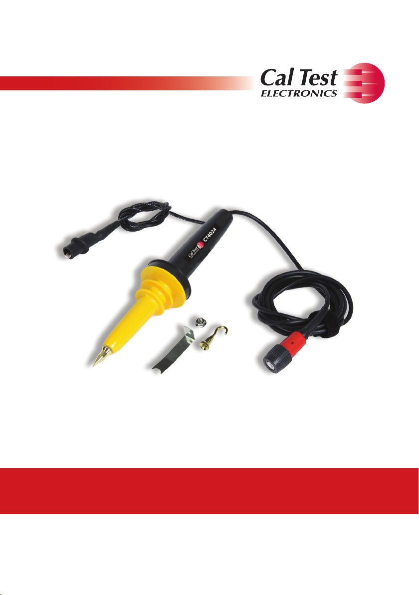
The Elditest CT4024 is an 8 kV High Voltage divider probe for use with
both digital and analog oscilloscopes.
Features
z Measures up to: 8 kV (DC + ACpk) or 6 kVrms AC
z 40 MHz bandwidth
z Voltage dividing of 1000:1
z Frequency compensation
800-572-1028 caltestelectronics.com 4

2 Using the Probe
1. Connect the probe to the BNC input of the oscilloscope.
2. Select the desired volts/division range on your oscilloscope.
3. If possible, always turn the high voltage source off before
connecting or disconnecting the probe.
4. Connect the divider probe ground lead (alligator clip) to a good
earth ground or reliable chassis ground.
5. Before turning on the high voltage source, be certain the
operator is not touching any part of the device under test.
6. Turn on the high voltage source.
7. You will now be able to analyze the voltage waveform on your
oscilloscope.
8. Turn off the high voltage source.
9. Disconnect the High Voltage Probe from the high voltage source
BEFORE disconnecting the ground clip lead.
800-572-1028 caltestelectronics.com 5
3 Frequency Compensation
Proper compensation of the probe is required to assure amplitude
accuracy of the waveform being measured by matching the probe to
the oscilloscope’s input capacitance. Compensation should be adjusted
whenever the probe is connected to, or transferred between, oscilloscopes.
The procedure is the same as for a x10 passive probe.
z Connect the probe to the oscilloscope.
z Connect probe tip to square-wave generator.
z Adjust the square wave generator for 10 V amplitude.
z Adjust the oscilloscope for a time base of 500 µs/div.
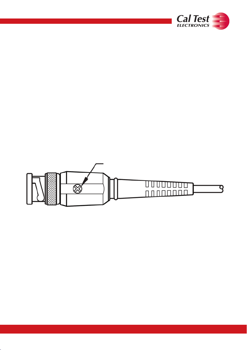
z Turn trimmer (Figure 1) to adjust the compensation on the probe
making a flat pulse top.
Frequency Compensation Trimmer
Figure 1: Trimmer on BNC
800-572-1028 caltestelectronics.com 6

Figure 2 shows how over- and under-compensated pulse responses
will look.
Figure 2: Over/Under Compensation
Figure 3 shows a perfectly compensated probe.
Figure 3: Good Compensation
800-572-1028 caltestelectronics.com 7
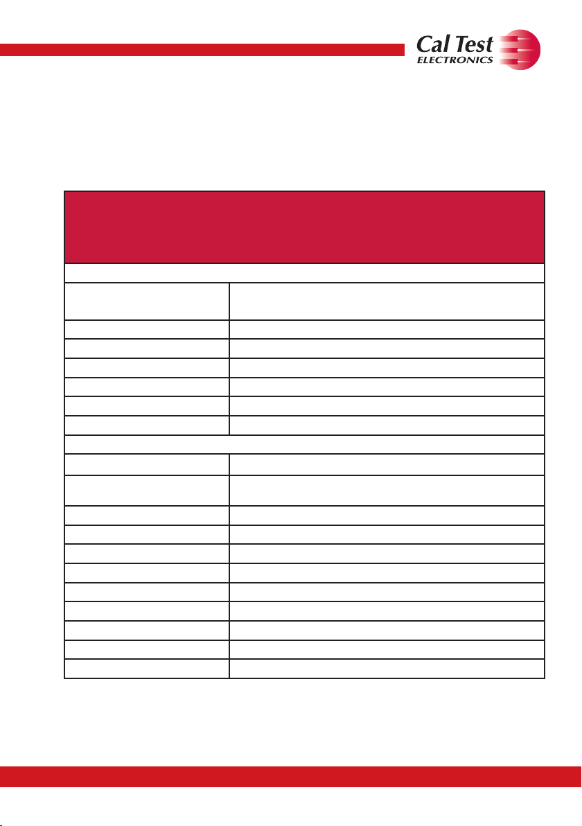
4 Specications
All specications apply to the unit after a temperature stabilization time
of 15 minutes over an ambient temperature range of 25 °C ± 5 °C.
CT4024
8 kV High Voltage Probe
Operating Parameters
Maximum Input Voltage
(CAT I)
Division Ratio 1000:1
Bandwidth 40 MHz (-3 dB)
Compensation Range 5 pF to 50 pF
Temperature Coefcient ≤200 ppm/ºC
Input Resistance 100 MΩ ± 5%
Rise Time ≤9 ns
Accuracy
DC Volts ±3% (below 8 kV)
AC Volts
General
Cable Length
Designed for Use in
Operating Environment
Storage Temperature
Humidity
Dimensions
Weight
Warranty
≤80% relative humidity at 104ºF (40ºC)
8 kV (DC + ACpk)
6 kVrms AC
±3% at 1 kHz
±3 dB 0 to 40 MHz
6.6 ft (2 m)
Pollution Degree 2
32ºF to 122ºF (0ºC to 50ºC)
-4ºF to 158ºF (-20ºC to 70ºC)
8.3 in (21 cm)
0.40 lbs (180 g)
One-year warranty
Specications are subject to change without notice. To ensure the most
current version of this manual, please download the current version
from our website: caltestelectronics.com.
800-572-1028 caltestelectronics.com 8

5 Voltage Derating Curve
WARNING
When measuring higher frequency signals, be sure to comply with the
Voltage vs Frequency Derating Curve.
Figure 4: Voltage Derating Curve
800-572-1028 caltestelectronics.com 9

6 Cleaning
Clean only the exterior probe body and cables. Use a soft cotton cloth
lightly moistened with a mild solution of detergent and water. Do not
allow any portion of the probe to be submerged at any time.
WARNING
Dry the probe thoroughly before attempting to make voltage
measurements.
CAUTION Do not subject the probe to solvents or solvent fumes as
these can cause deterioration of the probe body and cables.
7 Service & Warranty Information
Limited One-Year Warranty
Cal Test Electronics warrants this product to be free from defective
material or workmanship for a period of 1 year from the date of original
purchase. Under this warranty, Cal Test Electronics is limited to
repairing the defective device when returned to the factory, shipping
charges prepaid, within the warranty period.
Units returned to Cal Test Electronics that have been subject to abuse,
misuse, damage, or accident, or have been connected, installed, or
adjusted contrary to the instructions furnished by Cal Test Electronics,
or that have been repaired by unauthorized persons, will not be
covered by this warranty.
Cal Test Electronics reserves the right to discontinue models, change
specications, price, or design of this device at any time without notice
and without incurring any obligation whatsoever.
The purchaser agrees to assume all liabilities for any damages and/or
bodily injury which may result from the use or misuse of this device by
the purchaser, his employees, or agents.
800-572-1028 caltestelectronics.com 10

This warranty is in lieu of all other representations or warranties
expressed or implied and no agent or representative of Cal Test
Electronics is authorized to assume any other obligation in connection
with the sale and purchase of this device.
Service
If you have a need for calibration or repair services, technical, or sales
support, please contact us:
22820 Savi Ranch Parkway
Yorba Linda, CA 92887
800-572-1028 or 714-221-9330
caltestelectronics.com
800-572-1028 caltestelectronics.com 11

Notes
800-572-1028 caltestelectronics.com 12

800-572-1028 caltestelectronics.com 13

800-572-1028 caltestelectronics.com 14

800-572-1028 caltestelectronics.com 15
 Loading...