

CT3686 & CT3687
User Manual

Safety Summary
To avoid personal injury and/or product damage, review and comply
with the following safety precautions. These precautions apply to both
operating and maintenance personnel and must be followed during all
phases of operation, service, and repair of this probe.
A WARNING statement calls attention to an operating procedure,
practice, or condition, which, if not followed correctly, could result in
injury or death to personnel.
A CAUTION statement calls attention to an operating procedure,
practice, or condition, which, if not followed correctly, could result in
damage to or destruction of parts or the entire product.
Do Not Work Alone
Do not work alone when working with high voltages.
Inspect the Probe
Inspect the probe and accessories for cracks and frayed or broken
leads before each use. If defects or damages are noted, DO NOT USE
the probe.
Dry Conditions
Hands, shoes, oor and work bench must be dry. Avoid making
measurements under humidity, dampness or other environmental
conditions that might affect safety.
Do Not Remove the Probe’s Casing
Removal of the probe’s casing may expose you to electric shock.
If necessary, disconnect the inputs and outputs of the probe before
opening the case.
Hazardous Contact
To avoid injury, remove jewelry such as rings, watches, and other
metallic objects. Do not touch exposed connections and components
when power is present.
Unexpected Charges
Hazardous voltages may be present in unexpected locations in circuitry
being tested when a fault condition in the circuit exists. Capacitors
800-572-1028 caltestelectronics.com 1

inside the instrument may retain a charge even if the instrument is
disconnected from its source of supply.
Use Only in Ofce-Type Indoor Setting
The probe is designed to be used in ofce-type indoor environments.
Do not operate the probe:
z In the presence of noxious, corrosive, or flammable fumes,
gases, vapors, chemicals, or finely-divided particulates.
z In environments where there is a danger of any liquid being
spilled on the probe.
z In air temperatures exceeding the specified operating
temperatures.
z In atmospheric pressures outside the specified altitude limits
or where the surrounding gas is not air.
Not for Critical Applications
This probe is not authorized for use in contact with the human body or
for use as a component in a life-support device or system.
Do Not Substitute Parts
Do not install substitute parts or perform any unauthorized modication
to the instrument.
Only Qualied Personnel
Only qualied personnel should use this probe. This differential
voltage probe is designed to be used by personnel who are trained,
experienced, or otherwise qualied to recognize hazardous situations
and who are trained in the safety precautions necessary to avoid
possible injury when using such a device.
Observe Maximum Working Voltage
Do not use the CT3686 or CT3687 probes above their maximum
working volatage ranges. See “Electrical Specications” on page 10.
Use Proper Power Source
To ensure this probe functions well, use four AA cells or 6 VDC/200
mA or regulated 9 VDC/120 mA mains adapter or power leads. Do not
operate this probe from a power source that applies more than the
800-572-1028 caltestelectronics.com 2
voltage speci ed.
Must be Grounded
This probe is grounded by the shell of the BNC connector through the
grounding conductor of the power cord of the measurement instrument.
Before making connections to the input leads of this probe, ensure
that the output BNC connector is attached to the BNC connector of
the measurement instrument, and that the measurement instrument
is properly grounded. Whenever it is likely that the ground protection
is impaired, you must make the instrument inoperative and secure it
against any unintended operation.
Use Fused Test Probes if Necessary
If this probe is intended to use for measurements in circuits of
installation CAT III, it should incorporate the use of fused test probes.
Compliance Statements
Disposal of Old Electrical & Electronic Equipment
(Applicable in the European Union and other European
countries with separate collection systems). This product
is subject to Directive 2012/19/EU of the European
Parliament and the Council of the European Union on
waste electrical and electronic equipment (WEEE), and in
jurisdictions adopting that Directive, is marked as being
put on the market after August 13, 2005, and should not
be disposed of as unsorted municipal waste. Please utilize
your local WEEE collection facilities in the disposition of
this product and otherwise observe all applicable requirements.
This probe is in compliance with IEC-61010-031 CAT II, Pollution
Degree 2.
800-572-1028 caltestelectronics.com 3

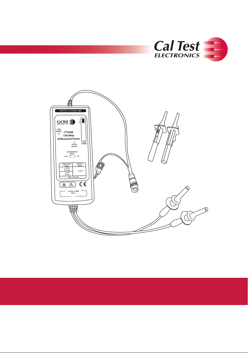
1 Introduction
1.1 Overview
Differential probes allow safe, accurate measurement between two
voltage points where neither point is referenced to ground. The
CT3686 and CT3687 both offer 100 MHz bandwidth and can test up
to ±700 V (DC + AC peak) and ±1400 V (DC + AC peak), respectively.
Compatible with oscilloscopes from all major manufacturers, the
probes can be battery operated, powered by a universal adapter
(optional), or powered by USB power lead (optional) if the oscilloscope
is so equipped.
Features:
z Meets IEC 61010-031 safety standard
z 100 MHz bandwidth (-3 dB)
z Up to ±700 V (DC + AC peak) common mode (CT3686)
z Up to ±1400 V (DC + AC peak) common mode (CT3687)
z Selectable attenuation settings of 10x/100x (CT3686)
z Selectable attenuation settings of 100x/1000x (CT3687)
z Power and over-range indicators
z High accuracy (±2%)
z High CMRR
z Powered by 4 AA batteries (included)
z Power adapter, CT3723 (optional)
z USB power lead, CT4122 (optional)
800-572-1028 caltestelectronics.com 4
1.2 Initial Inspection
This probe is tested prior to shipment. It is therefore ready for
immediate use upon receipt. An initial physical inspection should be
made to ensure that no damage has been sustained during shipment.
After the inspection, verify the contents of the shipment. The kit
contains:
z Differential probe
z (2) Hook probes, black & red
z (4) AA batteries
z Offset adjustment tool
z User manual
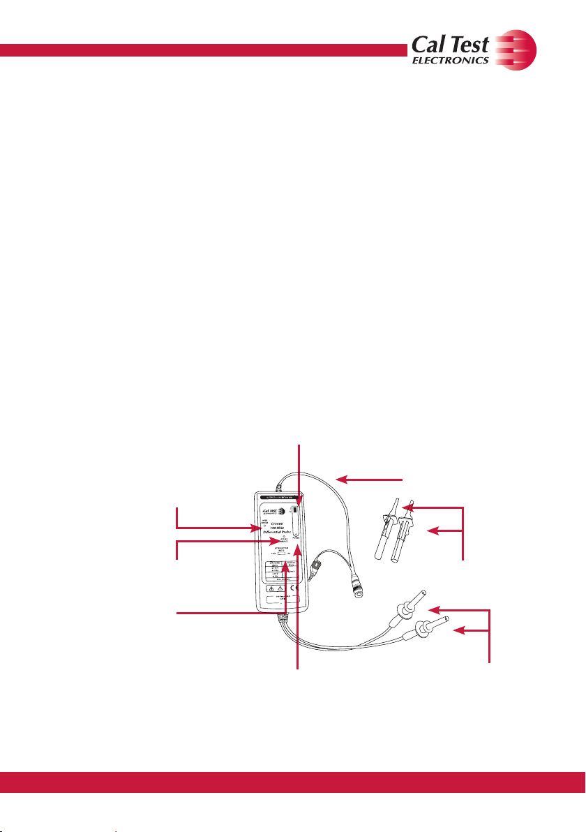
2 Product Description
2.1 Front Panel
Output BNC
Power On/O Switch
Over-range Indicator
cable, 90 cm,
with 4 mm
Banana Plug
Ground Lead
Oset Adjustment
Attenuation
Function Switch
LED Power Indicator
Figure 1 Front Panel Diagram
800-572-1028 caltestelectronics.com 5
Hook Probes
Leads,
60 cm

3 Using the Probe
3.1 Replacing the Batteries
Before using the differential probe for the rst time, the batteries
supplied with the device must be inserted in the battery compartment
(unless you are using the power adapter or USB power lead).
WARNING
At the time of inserting or replacing the batteries, the input leads must
not be connected to an item to be tested. Never operate the probe with
the case open.
Slide back the battery cover. If necessary, the old AA batteries can then
be removed and the new ones inserted into the compartment. Always
ensure the batteries are positioned for proper polarity. After inserting
the batteries, close the case. When the batteries are low, the power
indicator will start to icker and dim.
3.2 Inspection Procedure
1. Connect the BNC output connector to the vertical input the
oscilloscope.
2. Power on the probe.
3. Set the oscilloscope input to DC coupling and 1V/div. Center
the trace on the display.
4. Set the attenuation of the oscilloscope to match the low
setting on the probe.
5. Connect the hook probes to the leads.
6. Connect the black hook probe to the ground connection on
the oscilloscope and the red hook probe to the test signal on
the oscilloscope (1 kHz for example).
7. A wave matching the test signal should display on the
screen of the oscilloscope and this means this probe is
working properly.
800-572-1028 caltestelectronics.com 6

3.3 Getting Started
1. Connect the hook probes to the leads.
2. Connect the probe to the oscilloscope with the BNC cable.
When using a portable or ungrounded oscilloscope, connect
the output ground lead to ground.
3. Switch the probe “ON.”
4. Switch to the desired attenuation ratio.
5. Use the hook probes to contact the circuit to be tested.
CAUTION
This probe is used to carry out differential measurements between
two points on the circuit under test. This probe is not for electrically
insulating the circuit under test and the measuring instrument.
3.4 Overrange Indicator
The overrange indicator lights when the voltage of the input signal
exceeds the linear operating range of the probe. When this happens,
the signal on the probe output may not accurately represent the signal
on the probe input.
800-572-1028 caltestelectronics.com 7
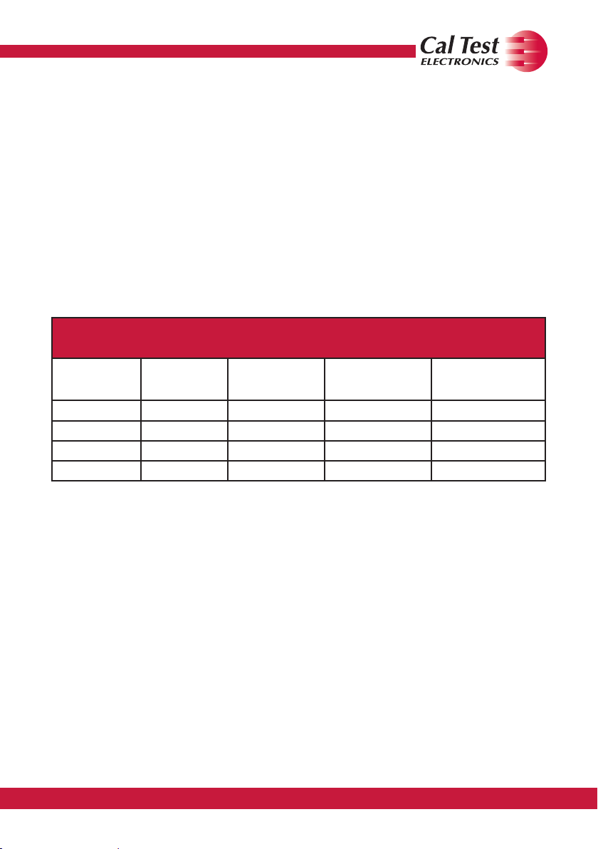
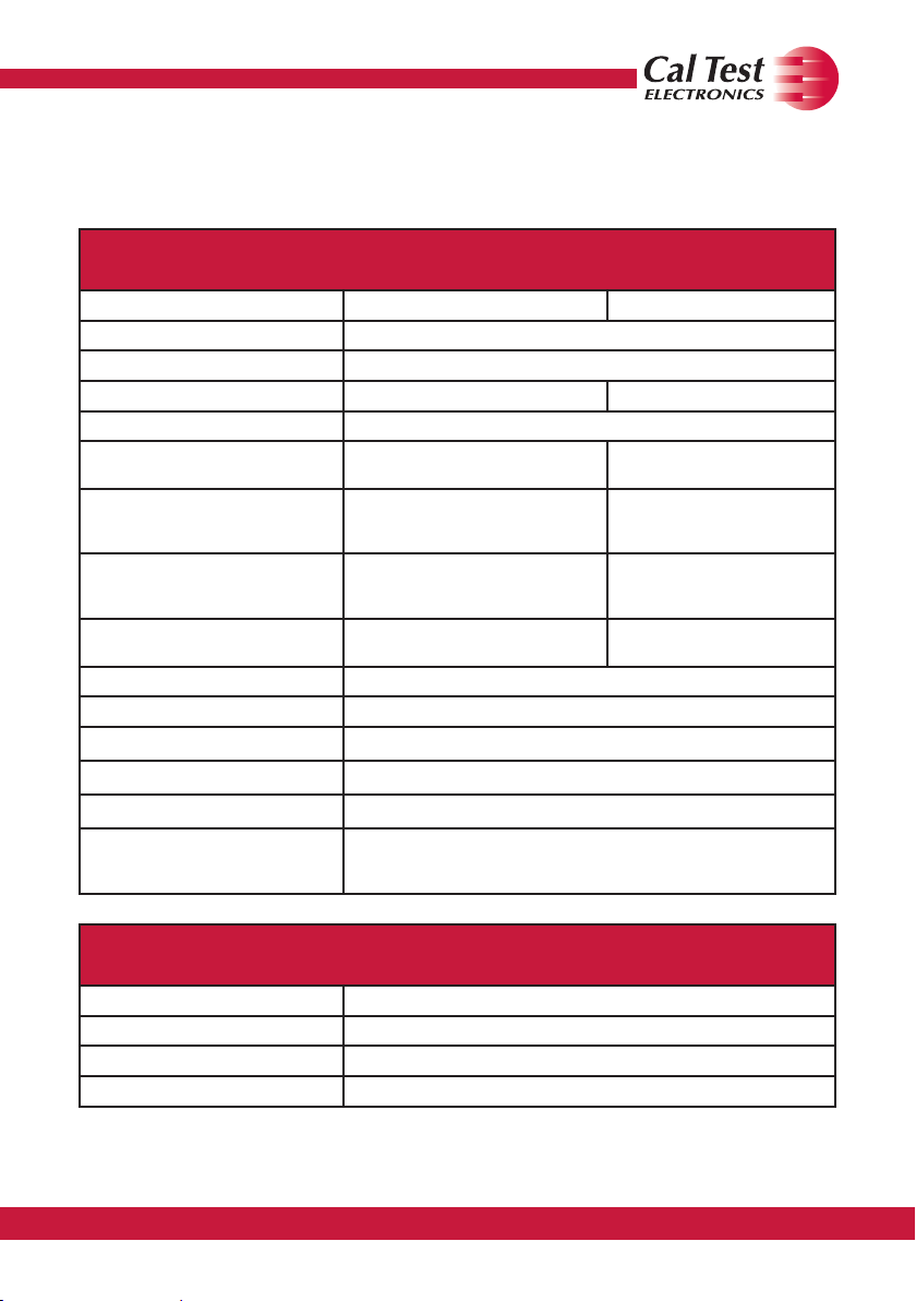
3.5 Vertical Scale on Oscilloscope
The actual vertical scale of the oscilloscope is equal to the attenuation
factor multiplied by the range of vertical scale selected on the
oscilloscope. For example, with the CT3686 set on attenuation 10x, the
oscilloscope on 0.5 V/div, the real vertical scale is 10 x 0.5 = 5 V/div.
With the probe on 100x, the real vertical scale is 100 x 0.5 = 50 V/div.
These values apply when the oscilloscope is set to the typical 1 MΩ
impedance input. When the oscilloscope is set to 50 Ω input, the actual
vertical scale will be doubled: 10 V/div for the 10x setting and 100 V/div
for the 100x setting. See Table 1.
Vertical Scale on Oscilloscope
Scope Input
Impedance
1 MΩ 10x 10x 0.5 V/div 5 V/div
1 MΩ 100x 100x 0.5 V/div 50 V/div
50 Ω 10x 20x 0.5 V/div 10 V/div
50 Ω 100x 200x 0.5 V/div 100 V/div
Table 1 Oscilloscope Readings
Probe
Attenuation
Setting
Actual
Attenuation
Setting
Vertical Scale
Reading on the
Oscilloscope
Actual Vertical
Scale of the
Oscilloscope
Offset Zero Procedure
The CT3686 and CT3687 can be adjusted to zero the probe’s offset
voltage using the offset adjustment tool supplied with the probe. Follow
this procedure to perform the offset adjustment.
1. Connect the probe to Channel 1 of the oscilloscope. Turn
on the probe power. You may use the USB power cable or
batteries to power the probe. Set the probe attenuation ratio
to the low setting (10x for CT3686 and 100x for CT3687).
2. Short the + and - probe inputs together with the hook tips.
3. Turn on power to the oscilloscope. Leave both the
800-572-1028 caltestelectronics.com 8

instrument and the probe turned on for 30 minutes to
stabilize.
4. Press [Default Setup] and [Auto] on the oscilloscope.
5. Press the Channel 1 button, then press the Probe softkey
and set the attenuation to match that of the probe.
6. Set the oscilloscpe to DC coupled mode and the scope
offset to 0 volts.
7. Set the oscilloscope to average mode (x16) or high-
resolution mode to reduce oscilloscope noise.
8. Using the offset adjustment tool (included), adjust the probe
offset voltage to 0 volts
4 Cleaning
This probe does not require any particular cleaning. If necessary, clean
the case with a cloth slightly moistened with soapy water. Make sure
the probe is completely dry before reconnecting it to an oscilloscope.
WARNING
Dry the probe thoroughly before attempting to make voltage
measurements.
CAUTION
Do not subject the probe to solvents or solvent fumes as these can
cause deterioration of the probe body and cables.
800-572-1028 caltestelectronics.com 9
Specications
All specications apply to the unit after a temperature stabilization time of 20 minutes over an
ambient temperature range of 25 °C ± 5 °C.
Electrical Specications
CT3686 CT3687
Bandwidth (-3dB) 100 MHz (driving 1 MΩ oscilloscope input)
Rise Time (10%-90%) 3.5 ns
Attenuation ratio 10x/100x 100x/1000x
Accuracy ±2%
CMRR (typical)
Maximum Differential Input
Voltage
(DC + AC peak)
Maximum Common Mode Input
Voltage
(DC + AC peak)
Absolute Maximum Rated Input
Voltage (each side to ground)
Input Impedance 4 MΩ // 7 pF (each side to ground)
Output Voltage Swing ±7 V (driving 1 MΩ oscilloscope input)
Offset (typical) ±5 mV
Noise (typical) 0.9 mVrms
Source Impedance 50 Ω
Power Supply
-85 dB @ 50 Hz
-55 dB @ 1 MHz
±70 V @ 10x
±700 @ 100x
±700 V ±1400 V
700 Vrms CAT II 1000 Vrms CAT II
4 AA batteries (included) or
CT3723 power adapter (optional)
CT4122 USB power lead (optional)
-80 dB @ 60 Hz
-50 dB @ 1 MHz
±140 V @ 100x
±1400 @ 1000x
Mechanical Characteristics
Weight 500 g
Dimensions 207 x 83 x 38 mm
BNC Cable Length 90 cm
Input Leads Length 30 cm each
800-572-1028 caltestelectronics.com 10

Environmental Characteristics
Operating Temp/Humidity -10°C to 40°C / Up to 85% RH
Storage Temp/Humidity -30°C to 70°C / Up to 85% RH
Pollution Degree Pollution Degree 2
Altitude
Operating: 3,000 m
Nonoperating: 15,300 m
Safety Specications
IEC 61010-031 CAT II
Specications are subject to change without notice. To ensure the most current version of this
manual, please download the current version from our website: caltestelectronics.com
5 Voltage Derating Curve
The derating curve of the absolute maximum input voltage in common
mode is show as follows:
CT3686 & CT3687 Maximum Input Voltage Derating Curve
10,000
1,000
1000 1000
100
20
10
Voltage (Vrms)
10
5
10
6
10
7
10
8
Frequency (Hz)
Figure 2 Derating Curve
800-572-1028 caltestelectronics.com 11

6 Service & Warranty Information
6.1 Limited One-Year Warranty
Cal Test Electronics warrants this product to be free from defective
material or workmanship for a period of 1 year from the date of original
purchase. Under this warranty, Cal Test Electronics is limited to
repairing the defective device when returned to the factory, shipping
charges prepaid, within the warranty period.
Units returned to Cal Test Electronics that have been subject to abuse,
misuse, damage or accident, or have been connected, installed or
adjusted contrary to the instructions furnished by Cal Test Electronics,
or that have been repaired by unauthorized persons, will not be
covered by this warranty.
Cal Test Electronics reserves the right to discontinue models, change
specications, price, or design of this device at any time without notice
and without incurring any obligation whatsoever.
The purchaser agrees to assume all liabilities for any damages and/or
bodily injury which may result from the use or misuse of this device by
the purchaser, his employees, or agents.
This warranty is in lieu of all other representations or warranties
expressed or implied and no agent or representative of Cal Test
Electronics is authorized to assume any other obligation in connection
with the sale and purchase of this device.
6.2 Service
If you have a need for calibration or repair services, technical or sales
support, please contact us:
22820 Savi Ranch Parkway
Yorba Linda, CA 92887
800-572-1028 or 714-221-9330
caltestelectronics.com
800-572-1028 caltestelectronics.com 12

800-572-1028 caltestelectronics.com 13

800-572-1028 caltestelectronics.com 14

© 2017 Cal Test Electronics450847-001
 Loading...