

Page 1
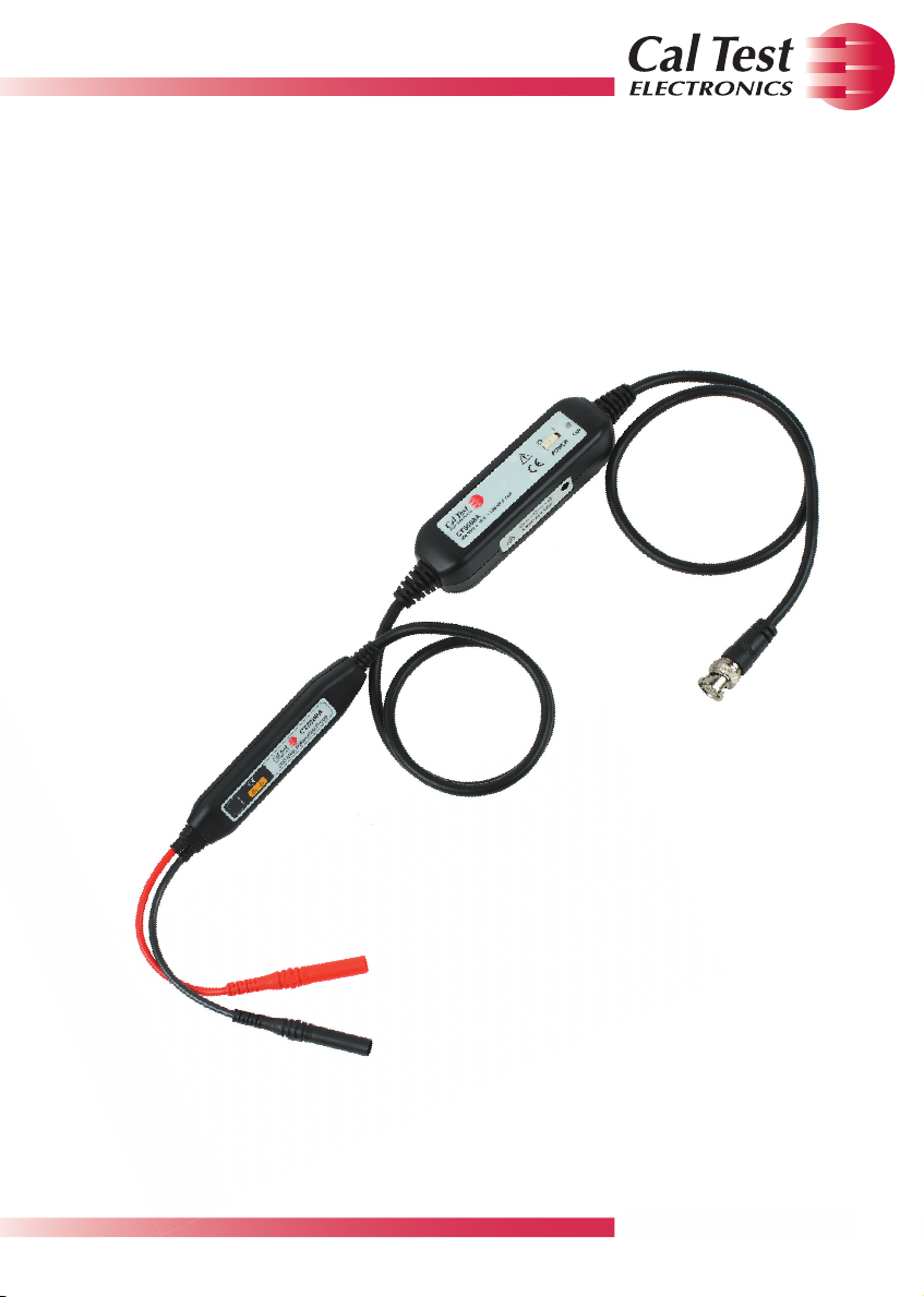
Active Differential Probe Kit, 200 MHz, 10x Small Signal ±20V
CT3688A
USER MANUAL
Page 2
CAL TEST ELECTRONICS
CT3688A Active Differential Probe Kit, User Guide
© Cal Test Electronics. All rights reserved.
Cal Test Electronics products are covered by US and foreign patents, issued
and pending. Information on this publication supersedes all earlier versions.
Specications are subject to change without notice.
Made in Taiwan
SYMBOLS AND TERMS
The following symbols may appear on the product or in the documentation.
Caution Symbol (ISO 7000-0434) – Statements or instructions
that must be consulted in order to nd out the nature of the
potential hazard and any actions which must be taken.
Caution, possibility of electric shock Symbol (IEC 604027-
6042) - To identify equipment that has the risk of electric shock.
A statement calling attention to an operating procedure,
WARNING
CAUTION
WARNING
practice, or condition, which if not followed correctly, could result
in damage to or destruction of parts or the entire product.
A statement calling attention to an operating procedure,
practice, or condition, which if not followed correctly, could result
in injury or death to personnel.
DEFINITIONS
POLLUTION (P) – addition of foreign matter solid, liquid or gaseous (ionized
gases), that may product a reduction of dielectric strength or surface
resistivity.
• Degree 2 (P2) – only non-conductive pollution occurs except that
occasionally a temporary conductivity caused by condensation is
expected.
MEASUREMENT CATEGORY (CAT) – classication of testing and measuring
circuit according to the type of mains circuits to which they are intended to
be connected.
• MEASUREMENT CATEGORY other than II, III, or IV: - measuring
circuits that are not directly connected to the mains supplies.
1
Page 3
CAL TEST ELECTRONICS
GENERAL SAFETY INFORMATION
Safety is compromised if instructions are not read, understood, and followed.
• Disconnect from all devices and sources before attaching test leads or
adapters.
• Check for damage before usage - Do not use if any part is damaged.
• Do not use in wet or explosive atmospheres.
CAUTION
CAUTION
WARNING
WARNING
WARNING
WARNING
WARNING
WARNING
Do not install substitute parts or perform any
unauthorized modication to the probe.
This probe is not authorized for use in contact with the
human body or for use as a component in a life-support
device or system.
Never exceed the maximum voltage or measurement
category of the probe and adapter assembly as
congured for usage.
Never remove the probe’s casing as this may expose you
to electric shock. If necessary, disconnect the inputs and
outputs of the probe before opening the case.
To avoid injury, remove jewelry such as rings, watches,
and other metallic objects. Do not touch exposed
connections and components when power is present.
Hazardous voltages may be present in unexpected
locations in circuitry being tested when a fault condition
in the circuit exists. Capacitors inside the instrument may
retain a charge even if the instrument is disconnected
from its source of supply.
Do not operate this probe from a power source that
applies more than the voltage specied.
This probe must be grounded by the shell of the BNC
connector through the grounding conductor of the power
cord of the measurement instrument. Before making
connections make sure the measurement instrument is
properly grounded. Whenever it is likely that the ground
protection is impaired, you must make the instrument
inoperative and secure it against any unintended
operation.
• If the probe is used in a manner not specied by this user guide, the
protections provided may be impaired.
2
Page 4

CAL TEST ELECTRONICS
DESCRIPTION
Dierential probes allow safe, accurate measurement between two voltage
points where neither point is referenced to ground. The CT3688A oers a 200
MHz bandwidth and can test up to ±60 V (DC + AC peak). Compatible with
oscilloscopes from all major manufacturers, the probe can be battery operated
or powered directly from an oscilloscope using the included USB cable.
Features:
• Meets IEC 61010-031 safety standard
• Small compact size
• Up to ±20 V dierential
• High accuracy ±1%
• 200 MHz bandwidth (-3 dB)
• Excellent CMRR
• Kit comes in foam-lined plastic case and contains:
• Dierential probe
• (2) Sprung hook probes,1000 V, CAT III, 20 A (black & red)
• (2) Alligator clips, 300 V, CAT II (black & red)
• 9 V Battery
• USB Power Cable
This probe is tested prior to shipment. It is therefore ready for immediate use
upon receipt. An initial physical inspection should be made to ensure that no
damage has been sustained during shipment.
3
Page 5

C
CAL TEST ELECTRONICS
B
A
D
• A - Active Dierential Probe, 200 MHz, 10x Small Signal ± 20 V
• B - CT4441, Insulated Medium Alligator Clips, 300 V, CAT II Pair (Black &
Red)
• C - CT4122, USB Power Cable
• D - CT4386, Insulated Sprung Hook Probes, 1000 V CAT III, 20 A, Pair
(Black & Red)
4
Page 6

CAL TEST ELECTRONICS
SPECIFICATIONS
All specications apply to the unit after a temperature stabilization time of about
20 minutes over an ambient temperature range of 25 °C ± 5 °C.
ELECTRICAL SPECIFICATIONS
Bandwidth (-3dB) 200 MHz
Rise Time (10%-90%) 1.75 ns
Attenuation Ratio 10x
Accuracy ±1%
CMRR (typical)
Maximum Dierential Input Voltage
(DC + AC peak)
Maximum Common Mode Input Voltage
(DC + AC peak)
Absolute Maximum Rated Input Voltage
(each side to ground)
Input Impedance 500 kΩ // 7 pF (each side to ground)
Output Voltage Swing ±2 V (driving 50 Ω oscilloscope input)
Oset (typical) ±2 mV
Noise (typical) 0.3 mVrms
Source Impedance 50 Ω
CT4122 USB Power Cable (included)
Power Supply
-80 dB @ 100 Hz
-50 dB @ 10 MHz
±20 V
±60 V
40 Vrms CAT I
or
9 V battery (included)
MECHANICAL SPECIFICATIONS
Weight 200 g
Dimensions (L x W x H) 111 mm x 22 mm x 14 mm
BNC Cable Length 120 cm
Input Leads Length 15 cm
5
Page 7

CAL TEST ELECTRONICS
ENVIRONMENTAL SPECIFICATIONS
Operating Temp/Humidity -10°C to 40°C / Up to 85% RH
Storage Temp/Humidity -30°C to 70°C / Up to 85% RH
Pollution Degree Pollution Degree 2
Altitude
Speci cations are subject to change without notice. To ensure the most current
version of this manual, please download the current version from our website:
caltestelectronics.com
CE COMPLIANCE
Low-Voltage Directive (LVD) 2014/35/EU
Standard EN 61010-031:2015
Reduction of Hazardous Substances Directive (RoHS 2) 2011/65/EU
+ AMD 2015/863 ANNEX III Exemption 6(c)
DISPOSAL OF OLD ELECTRICAL & ELECTRONIC EQUIPMENT
(Applicable in the European Union and other European countries
with separate collection systems). This product is subject to Directive
2012/19/EU of the European Parliament and the Council of the
European Union on waste electrical and electronic equipment (WEEE),
and in jurisdictions adopting that Directive, is marked as being put on
the market after August 13, 2005, and should not be disposed of as
unsorted municipal waste. Please utilize your local WEEE collection
facilities in the disposition of this product and otherwise observe all
applicable requirements.
Operating: 3,000 m
Non-operating: 15,300 m
6
Page 8

CAL TEST ELECTRONICS
VOLTAGE DERATING CURVE
The derating curve of the absolute maximum input voltage (either input to
ground) is shown as follows:
MAXIMUM INPUT VOLTAGE DERATING CURVE
100
60
Voltage (Vrms)
10
10 100 200 1000
Frequency (MHz)
7
Page 9

CAL TEST ELECTRONICS
USING THE PROBE
Power Connection
Connect the USB power cable to the USB interface on the front of the
oscilloscope and then to the input on the probe. See gure below.
Only use center pin positive supply, USB cable included
CAUTION
WARNING
or optional 9 VDC/300 mA AC wall adapter (CT3723 not
included).
At the time of powering on the probe, the input leads
must not be connected to the device under test (DUT).
Never operate the probe with the case open.
If powering by 9 V battery, slide the cover o the back of the battery box and
plug the battery in, making sure to position the battery for proper polarity. After
inserting the battery, close the case. See gure below.
When the battery is low, the power indicator will start to icker and dim.
8
Page 10

CAL TEST ELECTRONICS
INSPECTION PROCEDURE
1. Connect the BNC output connector to the vertical input of the
oscilloscope.
2. Power on the probe.
3. Set the oscilloscope input to DC coupling and 1V/div. Center the trace
on the display.
4. Set the attenuation setting on the oscilloscope to match the probe
(10x).
5. Connect the hook probes to the leads.
6. Connect the black hook probe to the ground connection on the
oscilloscope and the red hook probe to the test signal on the
oscilloscope (1 kHz for example).
7. A wave matching the test signal displayed on the screen of the
oscilloscope means the probe is working properly.
MAKING MEASUREMENTS
1. Connect the hook probes or alligator clips as needed to the leads.
2. Connect the probe to the oscilloscope with the BNC cable.
3. Switch the probe “ON.”
4. Set the attenuation setting on the oscilloscope to match the probe
(10x).
5. Set the input impedance setting on the oscilloscope to match the
probe (50Ω)
6. Connect to the circuit to be tested.
This probe is used to carry out dierential measurements
CAUTION
between two points on the circuit under test. This probe
is not for electrically insulating the circuit under test and
the measuring instrument.
CLEANING
Clean probe and accessories with cloth lightly moistened with water only. Dry
thoroughly before use.
9
Page 11

CAL TEST ELECTRONICS
SERVICE & WARRANTY INFORMATION
Limited One-Year Warranty
Cal Test Electronics warrants this product to be free from defective material or
workmanship for a period of 1 year from the date of original purchase. Under
this warranty, Cal Test Electronics is limited to repairing the defective device
when returned to the factory, shipping charges prepaid, within the warranty
period.
Units returned to Cal Test Electronics that have been subject to abuse, misuse,
damage or accident, or have been connected, installed or adjusted contrary to
the instructions furnished by Cal Test Electronics, or that have been repaired by
unauthorized persons, will not be covered by this warranty.
Cal Test Electronics reserves the right to discontinue models, change
specications, price, or design of this device at any time without notice and
without incurring any obligation whatsoever.
The purchaser agrees to assume all liabilities for any damages and/or bodily
injury which may result from the use or misuse of this device by the purchaser,
his employees, or agents.
This warranty is in lieu of all other representations or warranties expressed or
implied and no agent or representative of Cal Test Electronics is authorized to
assume any other obligation in connection with the sale and purchase of this
device.
Service
If you have a need for calibration or repair services, technical or sales support,
please contact us:
22820 Savi Ranch Parkway
Yorba Linda, CA 92887
800-572-1028 or 714-221-9330
caltestelectronics.com
10
Page 12

UserMan_CT3688A451020-00_rA
 Loading...