

Cal Spas LTR20091002 User Manual
LTR20091002, Rev. B
1/30/09

Preparing for Your New Inground Spa
Clear Water Plan
Inground Spa Installation Checklist.......4
Planning the Best Location For Your Spa...4
Planning the Best Place for the Outdoor
Equipment Pack.......................5
Inground Spa Site Preparation...........5
Electrical Requirements – US and Canada..6
GFCI Wiring Diagram ..................7
Electrical Installation -- Europe..........8
RCD Wiring Diagram ...................9
Installing the Inground Shell ...........10
Equipment Pack Plumbing Connections...11
Plumbing Connections ................11
Electrical and Electronic Connection .....13
Pouring the Deck.....................16
9800 Electronic Control Operation
Diagnostic Messages..................20
Adjustable Jets ......................22
Diverter Knobs.......................22
Waterfalls ..........................22
Air Venturis .........................22
The Key to Clear Water ................23
Testing and Adjusting Spa Water........24
Sanitation...........................25
Filter Cleaning .......................27
Bather Load . . . . . . . . . . . . . . . . . . . . . . . . .27
Starting the Spa with Fresh Water.......28
Maintenance Schedule ................29
Del Zone Eclipse Ozonator .............30
Troubleshooting Water Clarity Problems..31
Cleaning and Maintenance
Removing and Reseating the Pillows.....32
Spa Cover...........................32
Draining Your Spa ....................33
Cleaning and Replacing the Filter........33
Winterizing (Cold Climate Draining) .....33
Cleaning the Cover, Shell and Pillows ....34
Appendix
Replacement Parts ...................36
Keeping Fit with your Cal Spa...........37
Cal Spas™ Chemicals..................39
Copyright 2008-2009 LMS, Inc. All rights reserved. Duplication without written consent is
strictly prohibited.
Cal Spas® is a registered trademark.
Due to continuous improvement programs, all models, operation, and/or specications are
subject to change without prior notice.
LTR20091002, Rev. B
1/30/09
CONTACT INFORMATION
For customer service, please contact
your authorized dealer immediately. If
you need additional information and/
or assistance, please contact:
LMS Customer Service Department
1462 East Ninth Street
Pomona, CA 91766.
Toll Free: 1-800-CAL-SPAS
Fax: 1-909-629-3890
www.calspas.com
www. c al sp a s. co m
Important Safety Instructions
When installing and using this electrical equipment,
always follow basic safety precautions. Following
these instructions will help make your rst spa session a pleasurable one.
104˚F (40˚C) are considered safe for a healthy
adult. Lower water temperatures are recommended
for young children and when spa use exceeds 10
minutes.
3
Read This First!
READ AND FOLLOW ALL INSTRUCTIONS
NOTE: A licensed electrician may be required to upgrade your standard receptacle and/or circuit breaker.
DANGER -- RISK OF ACCIDENTAL DROWNING: Do not allow children to be in or around a spa
unless a responsible adult supervises them. Keep
the spa cover on and locked when not in use. See
instructions enclosed with your cover for locking procedures.
DANGER -- RISK OF INJURY: The suction ttings
in this spa are sized to match the specic water ow
created by the pump. Should the need arise to re-
place the suction ttings, or the pump, be sure the
ow rates are compatible.
DANGER -- RISK OF INJURY: Never operate the
spa if the suction tting or lter baskets are broken
or missing.
DANGER -- RISK OF INJURY: Never replace a
suction tting with one that is rated less than the
ow rate marked on the original suction tting.
DANGER -- RISK OF ELECTRIC SHOCK: Install
the spa at least ve feet (1.5 meters) from all metal
surfaces. As an alternative, a spa may be installed
within 5 feet of metal surfaces if each metal surface
is permanently bonded by a minimum #8 AWG solid
copper conductor to the outside of the spa’s control
box.
DANGER -- RISK OF ELECTRIC SHOCK: Do
not permit any external electrical appliances, such
as lights, telephones, radios, televisions, and etc.,
within ve feet (1.5 meters) of the spa. Never attempt to operate any electrical device from inside
the spa. This does not apply to lights built in to the
spa as factory options from Cal Spas™.
WARNING -- RISK OF INJURY
The spa water should never exceed 104˚F (40˚C).
Water temperatures between 100˚F (38˚C) and
High water temperatures have a high potential for
causing fetal damage during pregnancy. Women
who are pregnant, or who think they are pregnant,
should always check with their physician prior to spa
usage.
The use of alcohol, drugs or medication before or
during spa use may lead to unconsciousness, with
the possibility of drowning.
Persons suffering from obesity, a medical history of
heart disease, low or high blood pressure, circulatory system problems or diabetes should consult a
physician before using the spa.
Persons using medications should consult a physician before using the spa since some medications
may induce drowsiness while others may affect
heart rate, blood pressure and circulation.
Hyperthermia Danger
Prolonged exposure to hot air or water can induce
hyperthermia. Hyperthermia occurs when the inter-
nal temperature of the body reaches a level 3˚F to
6˚F above the normal body temperature of 98.6˚F
(or 2˚C to 4˚C above 37˚C). While hyperthermia
has many health benets, it is important not to allow
your body’s core temperature to rise above 103˚F
(39.5˚C). Symptoms of excessive hyperthermia in-
clude dizziness, lethargy, drowsiness and fainting.
The effects of excessive hyperthermia may include:
Failure to perceive heat•
Failure to recognize the need to exit spa or hot •
tub
Unawareness of impending hazard•
Fetal damage in pregnant women•
Physical inability to exit the spa•
Unconsciousness•
WARNING: The use of alcohol, drugs, or medication can greatly increase the risk of fatal hyperthermia.
2009 Inground Spas
LTR20091002, Rev. B
www. c al sp a s. co m
4
Preparing for Your New Inground Spa
Most cities and counties require permits for exterior construction and electrical circuits. In addition, some
communities have codes requiring residential barriers such as fencing and/or self-closing gates on property to
prevent unsupervised access to the property by children. Your dealer can provide information on which permits
may be required and how to obtain them prior to the delivery of your Cal Spa.
Inground Spa Installation Checklist
Before Delivery
Planning the Best Location For Your Spa
Preparing for Your New Inground Spa
Safety First
Do not place your spa within 10 feet (3 m) of overhead power lines.
Make sure the spa is positioned so that access to the
equipment compartment and all side panels will not
be blocked. Be certain that your installation will meet
all city and local safety codes and requirements.
Consider How You Will Use Your Spa
How you intend to use your spa will help you determine where you should position it. For example,
will you use your spa for recreational or therapeutic
purposes? If your spa is mainly used for family recreation, be sure to leave plenty of room around it for
activity. If you will use it for relaxation and therapy,
you’ll probably want to create a specic mood around
it.
Plan for Your Environment
If you live in a region where it snows in the winter
or rains frequently, place the spa near a house entry.
By doing this, you will have a place to change clothes
and not be uncomfortable.
Consider Your Privacy
In a cold-weather climate, bare trees won’t provide
much privacy. Think of your spa’s surroundings during all seasons to determine your best privacy op-
Plan your delivery route
Choose a suitable location for the shell and
equipment pack
Excavate the hole
Install dedicated electrical supply
Install dedicated NG line for gas heater
After Delivery
Install shell in ground
Install equipment pack
Connect plumbing
Connect electrical components
Pour the deck
tions. Consider the view of your neighbors as well
when you plan the location of your spa.
Provide A View With Your Spa
Think about the direction you will be facing when
sitting in your spa. Do you have a special landscaped
area in your yard that you nd enjoyable? Perhaps
there is an area that catches a soothing breeze during the day or a lovely sunset in the evening.
Keep Your Spa Clean
Prevent dirt and contaminants from being tracked
into your spa by placing a foot mat at the spa’s entrance where the bather’s can clean their feet before
entering your spa. You may also consider keeping a
small water-lled basin nearby for bathers to rinse
their feet before entering your spa.
In planning your spa’s location, consider a location
where the path to and from the house can be kept
clean and free of debris.
Allow For Service Access
Many people choose to install a decorative structure
around their spa. If you are installing your spa with
any type of structure on the outside, such as a gazebo, remember to allow access for service. It is always
best to design special installations so that the spa can
still be accessed.
2009 Inground Spas
LTR20091002, Rev. B
www. c al sp a s. co m
Planning the Best Place for the Outdoor Equipment Pack
The Designer Spa series requires an external equipment pack. When locating the outdoor equipment
pack, you will want to consider the following:
The equipment pack must be located within a •
maximum of 15 feet from the spa.
owner’s manual for important location and safety
information.)
The equipment base and heater must be placed •
on either a 3 1/2” cement slab or 3” paving
stones.
5
Preparing for Your New Inground Spa
Ensure the equipment running its normal ltra-•
tion cycles does not make too much noise for spa
owners and/or neighbors.
Ensure the equipment can be easily serviced for •
lter cleaning and periodic inspections in the location chosen.
If you are using a gas heater, you will need to •
consider wind and drafts as well as heater ex-
haust for proper heater placement. (See heater
Inground Spa Site Preparation
Ensure there is enough room for the spa and •
equipment.
Plan for proper electrical and gas service to both •
the equipment area and spa side.
Ensure the required at, level foundation can be •
constructed in the area chosen.
The spa must be properly back-lled with wet •
sand, underneath and on all four sides.
Never place any spa in a sealed area. Water must •
be able either to be absorbed into the surrounding area or channeled away. Water build-up under and/or around the spa, will cause the spa to
oat out of the ground.
Grading Prior to Excavation
Selection of the Designer Spas site will determine
how much grading will have to be accomplished prior
to the actual dig for the spa. Naturally, a level area is
best because it will require the least amount of preparation for the dig, but in many cases there is no level
area, therefore, the site must be prepared to accept
the spa prior to dig. The spa site should be elevated
slightly higher than the surrounding area.
When dealing with slopes, the severity of the slope
will determine if retaining walls must be built in order
to have a level area for the spa. If the slope is relatively minor, contact your local building safety.
Site Excavation – Hard Bottom
For hard bottom placement for inground spas, you
will need a smooth and at concrete surface at least
Make sure the equipment area selected will not •
be in an area where water could run or stand.
If the area receives direct sunlight, you will want •
to provide some protection for the equipment
portion of the equipment pack.
The equipment pack and heater are delivered separately. Do not cover gas heaters unless properly vent-
ed. (See heater owner’s manual for important safety
information.)
4” thick as large as the bottom contact points. Be
sure not to seal the bottom off and making a sealed
box. You will need adequate water drainage for escape under the spa. A gravel beds around the concrete base will help with this.
Site Excavation – Sand Bottom
With the spa area and all elevations planned including your decided type of decking, you are now ready
to proceed with the dig. An ideal excavation is one
that is as close as possible to the dimensions of the
spa shell, but with the following rules in mind. The
excavation should be 2” to 4” deeper than the actual
spa for your sand bed. The sand bed is to level the
spa shell and provide a perfect support base with no
voids when the spa is lowered into the hole. Your
excavation should be approximately one foot longer
and one foot wider than the spa shell. This will allow
for a six inch over dig all the way around the spa once
it is in place. Additional hand excavation will be re-
quired to insure the skimmer will t in the excavation
when attached to the spa.
Sand or rock dust must be used to bed the shell into
the excavation and for backll. In no event is dirt to
be used. One of the easiest ways to know how much
sand is needed to be placed on the bottom of the
excavation is to set a grade stake at all four corners,
and one on each side of the center line in the bottom
of the hole. If there are areas that are deeper than
2” to 4”, these can be lled with sand and are of no
consequence.
2009 Inground Spas
LTR20091002, Rev. B
www. c al sp a s. co m
6
Electrical Requirements – US and Canada
All 240V spas must be permanently connected (hard
wired) to the power supply. These instructions de-
scribe the only acceptable electrical wiring procedure.
Spas wired in any other way will void your warranty
and may result in serious injury. See the wiring diagram on page 7.
When installed in the United States, the electrical
wiring of this spa must meet the requirements of National Electric Code, ANSI/NFPA 70-2008 and any applicable local, state, and federal codes. The electrical
circuit must be installed by an electrical contractor
and approved by a local building / electrical inspector.
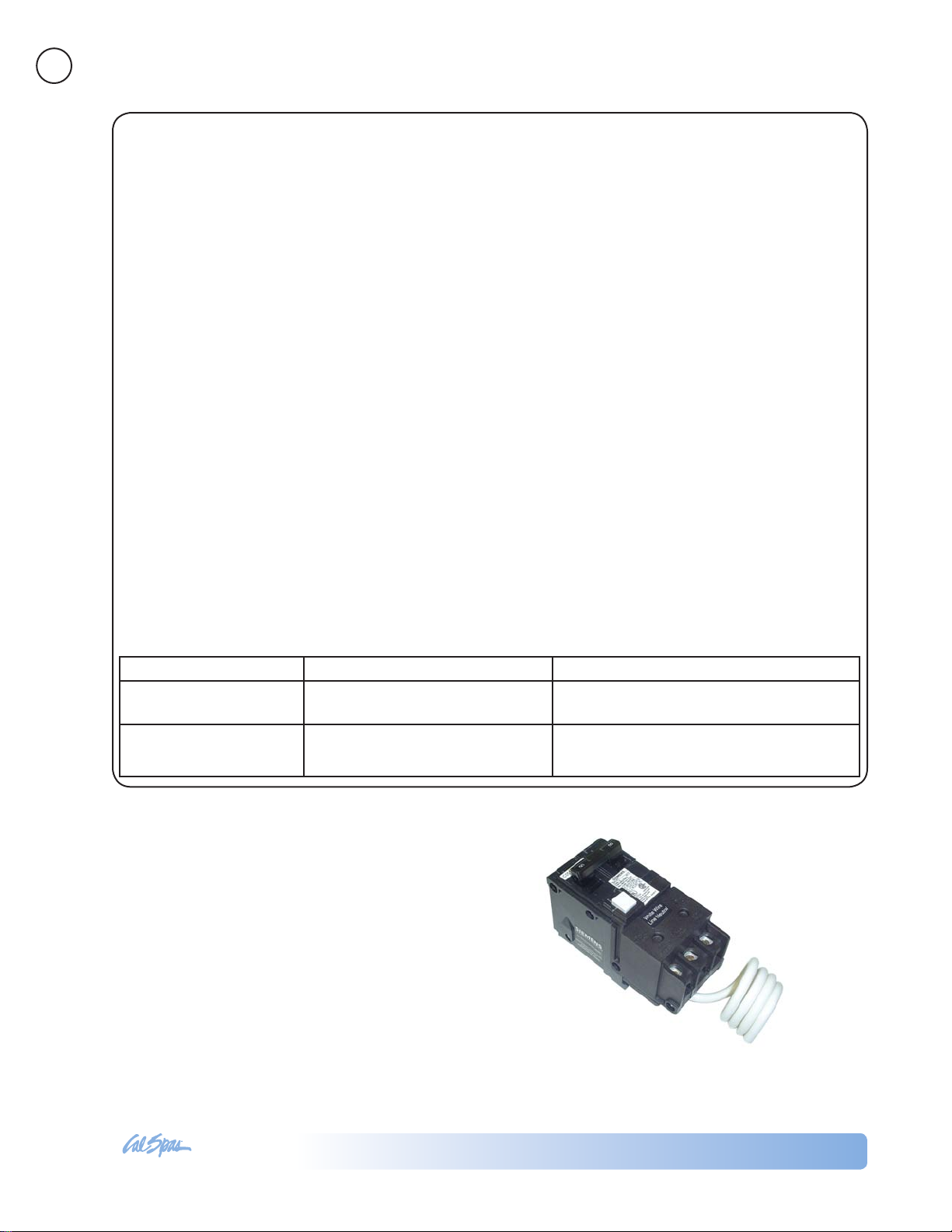
GFCI and Wiring Requirements
The power supplied to the spa must be on a dedicated GFCI protected circuit as required by ANSI/
NFPA 70 with no other appliances or lights sharing
the power.
Preparing for Your New Inground Spa
Use copper wire with THHN insulation. Do not use
aluminum wire.
Use the table below to determine your GFCI and wiring requirements.
When NEC requires the use of wires larger than #6
AWG, install a junction box near the spa and use #6
AWG wire between the junction box and the spa.
Wire runs over 85 feet must increase wire gauge to
the next lower number. For example: A normal 50
amp GFCI with four #8 AWG Copper wires run over
85 feet would require you to go to four #6 AWG copper wires.
Read and follow the heater manufacturer’s safety and
installation instructions prior to installation and operation. Incorrect installation may damage the heater
and void its warranty.
Testing the GFCI Breaker
Test the GFCI breaker prior to rst use and periodically when the spa is powered. To test the GFCI breaker
follow these instructions (spa should be operating):
Press the TEST button on the GFCI. The GFCI will 1.
trip and the spa will shut off.
Reset the GFCI breaker by switching the breaker 2.
to the full OFF position, wait a moment, then turn
the breaker back on. The spa should have power
again.
Spa Model GFCI Required Wires Required
Designer inground spas
with one 5.5 kW heater
Designer inground spa
with two 5.5 kW heaters
One 50 amp GFCI Four #8 AWG copper wires
Service 1: One 50 amp GFCI
Service 2: One 30 amp GFCI
Service 1: Four #8 AWG copper wires
Service 2: Three #8 AWG copper wires
2009 Inground Spas
LTR20091002, Rev. B
www. c al sp a s. co m
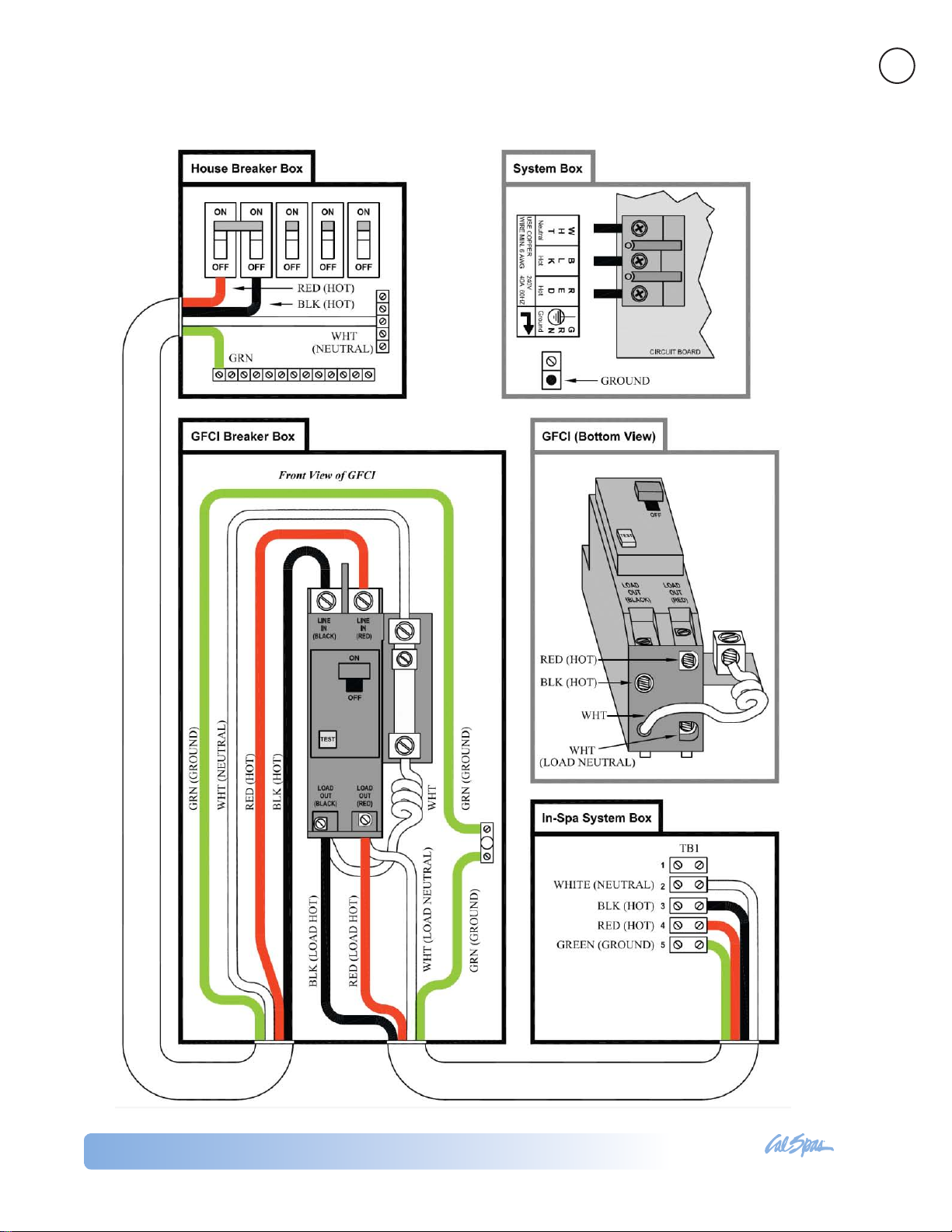
GFCI Wiring Diagram
7
Preparing for Your New Inground Spa
2009 Inground Spas
LTR20091002, Rev. B
www. c al sp a s. co m
8
Electrical Installation -- Europe
All 230V spas must be permanently connected (hard
wired) to the power supply. These instructions de-
scribe the only acceptable electrical wiring procedure.
Spas wired in any other way will void your warranty
and may result in serious injury.
This the only acceptable electrical wiring procedure.
Spas wired in any other way will void your warranty.
See the wiring diagram on page 9.
The electrical wiring of this spa must meet the requirements of any applicable local, state, and federal
codes. The electrical circuit must be installed by an
electrical contractor and approved by a local building
/ electrical inspector.
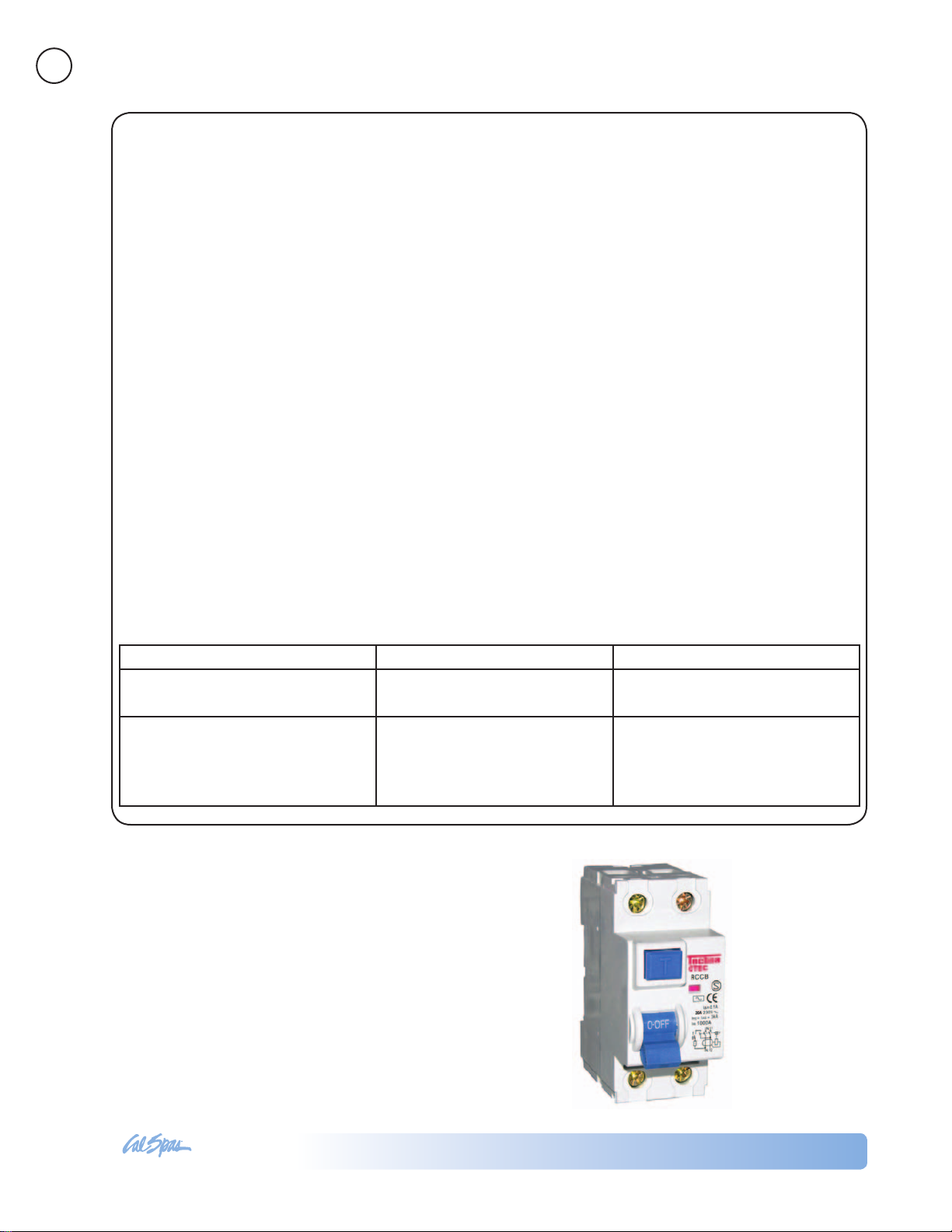
RCD and Wiring Requirements
The power supplied to the spa must be on a dedicated RCD protected circuit with no other appliances
or lights sharing the power.
Preparing for Your New Inground Spa
Use copper wire with THHN insulation. Do not use
aluminum wire.
Use the table below to determine your GFCI and wiring requirements.
When wires larger than #6 AWG are required, install
a junction box near the spa and use #6 AWG wire
between the junction box and the spa.
Wire runs over 85 feet must increase wire gauge to
the next lower number. For example: A normal 50
amp RCD with four #8 AWG copper wires run over
85 feet would require you to go to four #6 AWG copper wires.
Testing the RCD Breaker
Test the RCD breaker prior to rst use and periodically when the spa is powered. To test the RCD breaker
follow these instructions (spa should be operating):
Press the TEST button on the RCD. The RCD will 1.
trip and the spa will shut off.
Reset the RCD breaker by switching the breaker 2.
to the full OFF position, wait a moment, then turn
the breaker back on. The spa should have power
again.
Spa Model GFCI Required Wires Required
Designer inground spas with one 3
kW heater
Designer inground spa with one 3
kW heater and one 5.5 kW heater
One 32 amp RCD or two 16 amp
RCDs
Service 1: One 32 amp RCD or
two 16 amp RCDs
Service 2: One 32 amp RCD or
two 16 amp RCDs
Four #10 AWG copper wires
Service 1: Four #10 AWG copper
wires
Service 2: Three #10 AWG copper
wires
2009 Inground Spas
LTR20091002, Rev. B
www. c al sp a s. co m
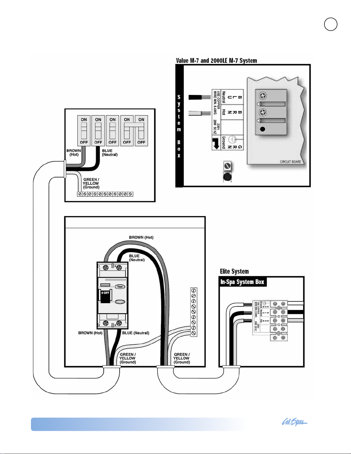
RCD Wiring Diagram
9
Preparing for Your New Inground Spa
2009 Inground Spas
LTR20091002, Rev. B

www. c al sp a s. co m
10
Installing the Inground Shell
Preparing for Your New Inground Spa
2009 Inground Spas
LTR20091002, Rev. B
www. c al sp a s. co m
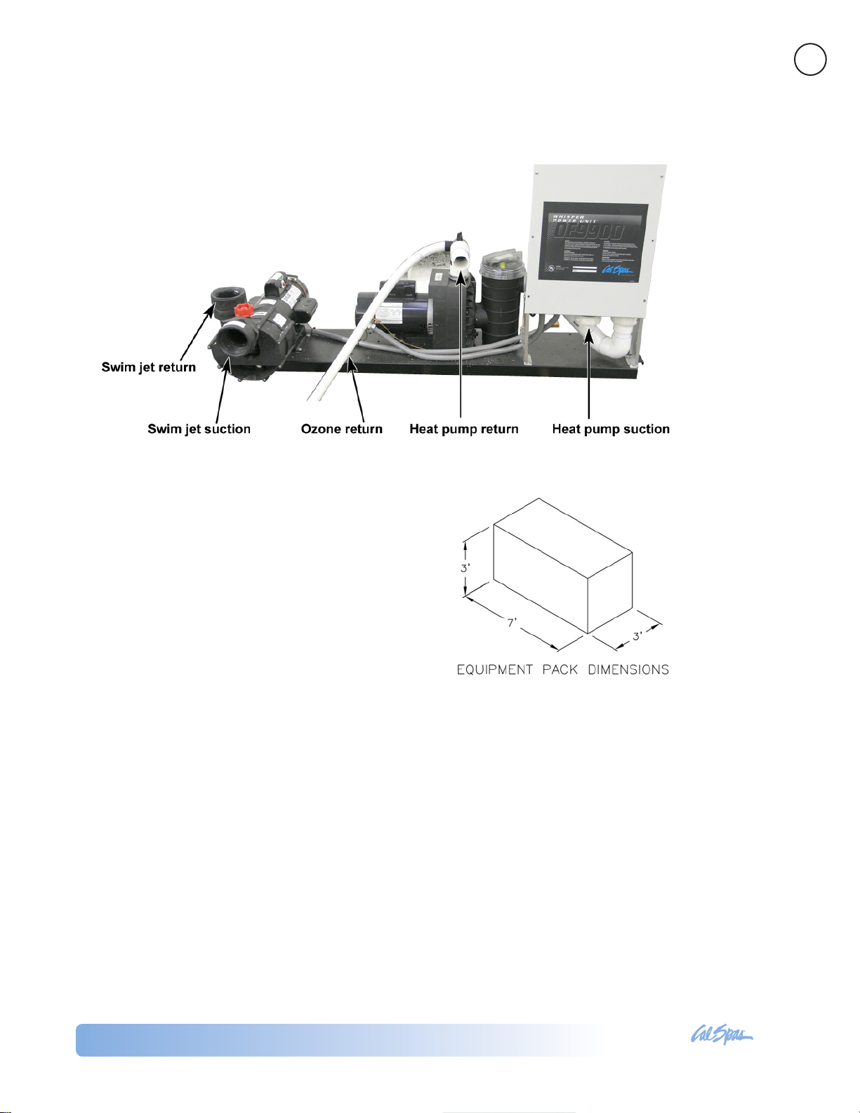
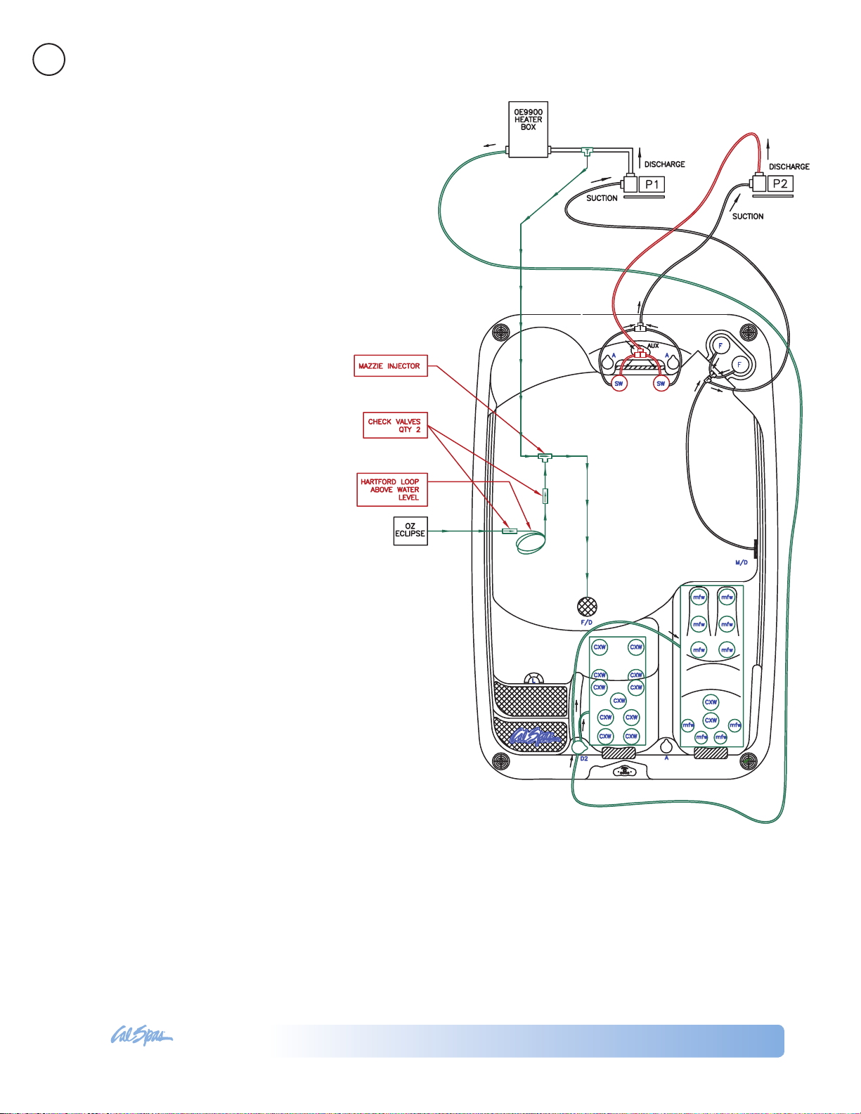
Equipment Pack Plumbing Connections
The example shown below is typical for a system with two pumps with external heater and external lter.
11
Preparing for Your New Inground Spa
Designer Spa Specications
DIJ401 and DIJ405:
Equipment pack weight = 250 lbs.
DIJ407:
Equipment pack weight = 300 lbs.
One 2.5 HP heat pump
One 4 HP swim pump
Note: Equipment pack cannot exceed 15 feet from
spa.
Plumbing Connections
IMPORTANT! Always check local codes prior to any
inground spa installation.
Once the spa and equipment are properly located, you
will want to lay out the plumbing run.
Trenches should be deep and wide enough to allow
all pipes to be buried below the frost line and should
be in as straight a line from the spa to the equipment
as possible. Check local code requirements for underground pipes. Always know what is under the ground
before you dig anywhere.
You will need 2” ex or PVC lines for your suction, intake, and air line. In ground spas have marked intake
and suction lines, making it easy nd and connect to
and from the spa and equipment pack.
The plumbing run should not be any longer than 15
feet to maximize water pressure. Another way to max-
imize water pressure is to limit (or even eliminate) the
use of 90˚ elbows in your plumbing run. A more direct
plumbing run using 45˚ elbows is more efcient, and
promotes increased water pressure.
Identifying Plumbing Lines
The spa’s plumbing lines are clearly marked during
water testing at the factory. This is done to assist installers in properly identifying the installation. We still
recommend that the installers verify plumbing lines
prior to gluing. This can be done by using one of the
following techniques.
2009 Inground Spas
LTR20091002, Rev. B
www. c al sp a s. co m
12
Air Test
The air test requires a wet/dry vacuum.
Locate the plumbing line you wish to
identify and secure the vacuum hose
to cut open end. Turn on the vacuum,
enter the spa and listen for vacuum
suction sound from inside the spa side
lter canister. If you hear the suction
sound in the canister, the line is properly marked and can be connected to
the suction side of the pump on the
equipment pack.
Water Test
The water test requires a garden hose
and water source. Locate the plumbing
line you wish to identify and secure the
outlet side of the garden hose to cut
open end. Turn on the water supply
to the garden hose, enter the spa and
look for water inside the spa side lter
canister. If you see water in the canis-
Preparing for Your New Inground Spa
ter the line is properly marked and can
be connected to the suction side of the
pump on the equipment pack.
If any plumbing line is not properly
marked or not marked at all, follow
either the air or water test procedure
until all lines are identied prior to gluing.
NOTE: Once complete, water test the
plumbing run for at least three days
prior to covering any plumbing trenches and back-lling spa cavity completely.
NOTE: Some local inspectors require
pressure testing the plumbing lines.
Although the spa is pressure tested at
the factory, local inspectors may insist
on pressure testing the plumbing run
between the spa and equipment pack.
Gate/Slice Valves
The use of gate valves is recommended on all plumb-
ing lines (both suction and return lines). These valves
are used to contain the spa’s water in either the equipment or the spa. This will assist in the pump priming
process and future servicing without needing to drain
the spa.
NOTE: When draining the spa to perform maintenance, always close the gate valves prior to draining.
This will maintain the pumps prime.
2009 Inground Spas
LTR20091002, Rev. B
 Loading...