

LTR20081002, Rev. A
1/28/08

Read This First!
Cleaning and Maintaining Your Spa
Important Safety Instructions. . . . . . . . . . . . . . .3
Basic Spa Information. . . . . . . . . . . . . . . . . . . . .3
Preparing for Your New Spa
In-Ground Spa Installation Checklist. . . . . . . . .5
Planning the Best Location For Your Spa . . . . .5
In-Ground Spa Site Preparation . . . . . . . . . . . . .6
Electrical Requirements – US and Canada . . . .7
Electrical Installation -- Europe . . . . . . . . . . . . .9
Installing the In-ground Shell . . . . . . . . . . . . . .11
Equipment Pack Plumbing Connections. . . . .12
Plumbing Connections . . . . . . . . . . . . . . . . . . .12
Electrical and Electronic Connection . . . . . . .14
Pouring the Deck . . . . . . . . . . . . . . . . . . . . . . . .17
Operating Your Spa
9800 Electronic Control Operation. . . . . . . . . .18
Adjustable Jets . . . . . . . . . . . . . . . . . . . . . . . . .22
Cleaning and Replacing the Filter . . . . . . . . . .24
Cleaning the Cover, Shell and Pillows. . . . . . .25
Prior to Spa Start-Up and Relling. . . . . . . . . .26
Filling and Powering Up Your Portable Spa . .26
Draining Your Spa . . . . . . . . . . . . . . . . . . . . . . .27
Winterizing (Cold Climate Draining). . . . . . . . .27
Water Quality Maintenance
Before You Begin . . . . . . . . . . . . . . . . . . . . . . . .28
Chemical Overview . . . . . . . . . . . . . . . . . . . . . .29
Chemical Descriptions . . . . . . . . . . . . . . . . . . .30
Traditional Chemical Start Up. . . . . . . . . . . . . .32
Bromine Clear Water Plan. . . . . . . . . . . . . . . . .33
Chlorine Clear Water Plan. . . . . . . . . . . . . . . . .33
Del Zone Eclipse Ozonator . . . . . . . . . . . . . . . .34
Maintenance . . . . . . . . . . . . . . . . . . . . . . . . . . . .34
Appendix
Diverter Knobs . . . . . . . . . . . . . . . . . . . . . . . . . .22
Air Venturis. . . . . . . . . . . . . . . . . . . . . . . . . . . . .22
Removing and Reseating the Pillows . . . . . . .23
Spa Cover . . . . . . . . . . . . . . . . . . . . . . . . . . . . . .23
Waterfalls . . . . . . . . . . . . . . . . . . . . . . . . . . . . . .23
Copyright 2008 Lloyds Material Supply, Inc. All rights reserved. Duplication without written
consent is strictly prohibited.
Cal Spas® is a registered trademark.
Due to continuous improvement programs, all models, operation, and/or specications are
subject to change without prior notice.
LTR20081002, Rev. A
1/28/08
Replacement Parts. . . . . . . . . . . . . . . . . . . . . . .35
Keeping Fit with your Cal Spa . . . . . . . . . . . . .37
Cal Spas™ Chemicals. . . . . . . . . . . . . . . . . . . .39
CONTACT INFORMATION
For customer service, please contact
your authorized dealer immediately. If
you need additional information and/or
assistance, please contact:
C.A.I. Customer Service Department
1462 East Ninth Street
Pomona, CA 91766.
Toll Free: 1-800-CAL-SPAS
Fax: 1-909-629-3890
www.calspas.com

Read This First!
Read This First!
Important Safety Instructions
When installing and using this electrical equipment,
always follow basic safety precautions. Following these
instructions will help make your rst spa session a
pleasurable one.
READ AND FOLLOW ALL INSTRUCTIONS
NOTE: A licensed electrician may be required to upgrade
your standard receptacle and/or circuit breaker.
DANGER -- RISK OF ACCIDENTAL DROWNING:
Do not allow children to be in or around a spa unless
a responsible adult supervises them. Keep the spa
cover on and locked when not in use. See instructions
enclosed with your cover for locking procedures.
DANGER -- RISK OF INJURY: The suction ttings
in this spa are sized to match the specic water ow
created by the pump. Should the need arise to replace
the suction ttings, or the pump, be sure the ow rates
are compatible.
DANGER -- RISK OF INJURY: Never operate the
spa if the suction tting or lter baskets are broken or
missing.
DANGER -- RISK OF INJURY: Never replace a suction
tting with one that is rated less than the ow rate marked
on the original suction tting.
DANGER -- RISK OF ELECTRIC SHOCK: Install the
spa at least ve feet (1.5 meters) from all metal surfaces.
As an alternative, a spa may be installed within 5 feet
of metal surfaces if each metal surface is permanently
bonded by a minimum #8 AWG solid copper conductor
to the outside of the spa’s control box.
DANGER -- RISK OF ELECTRIC SHOCK: Do not
permit any external electrical appliances, such as lights,
telephones, radios, televisions, and etc., within ve feet
(1.5 meters) of the spa. Never attempt to operate any
electrical device from inside the spa. This does not apply
to lights built in to the spa as factory options from Cal
Spas™.
WARNING -- RISK OF INJURY
The spa water should never exceed 104˚F (40˚C). Water
temperatures between 100˚F (38˚C) and 104˚F (40˚C)
are considered safe for a healthy adult. Lower water
temperatures are recommended for young children and
when spa use exceeds 10 minutes.
High water temperatures have a high potential for
causing fetal damage during pregnancy. Women who
are pregnant, or who think they are pregnant, should
always check with their physician prior to spa usage.
The use of alcohol, drugs or medication before or
during spa use may lead to unconsciousness, with the
possibility of drowning.
Persons suffering from obesity, a medical history of heart
disease, low or high blood pressure, circulatory system
problems or diabetes should consult a physician before
using the spa.
Persons using medications should consult a physician
before using the spa since some medications may
induce drowsiness while others may affect heart rate,
blood pressure and circulation.
Hyperthermia Danger
Prolonged exposure to hot air or water can induce
hyperthermia. Hyperthermia occurs when the internal
temperature of the body reaches a level 3˚F to 6˚F
above the normal body temperature of 98.6˚F (or 2˚C to
4˚C above 37˚C). While hyperthermia has many health
benets, it is important not to allow your body’s core
temperature to rise above 103˚F (39.5˚C). Symptoms
of excessive hyperthermia include dizziness, lethargy,
drowsiness and fainting. The effects of excessive
hyperthermia may include:
Failure to perceive heat
•
Failure to recognize the need to exit spa or hot tub
•
Unawareness of impending hazard
•
Fetal damage in pregnant women
•
Physical inability to exit the spa
•
Unconsciousness
•
WARNING: The use of alcohol, drugs, or medication
can greatly increase the risk of fatal hyperthermia.
Basic Spa Information
The following operating and maintenance instructions
are very important and must be followed carefully. With
the proper care and maintenance, your Cal Spa will
provide you with years of satisfaction and performance.
Do not be afraid to push buttons or turn knobs to learn
about your new Cal Spa, as it is built with quality materials
and excellent craftsmanship.
Your new Cal Spa has been engineered with a highpowered water pump that pushes water through various
2008 Inground Spa Owner’s Manual Page 3
LTR20081002, Rev. A

Read This First!
therapy jets, which will relax even the tightest muscles.
In addition to the water pressure, you can add air into
the spa water with air venturi handles located seat-side
that increase the intensity of your massage.
The ltering of this spa is very important. It will minimize
cleaning time and the amount of chemicals needed
to keep your spa water balanced. The two daily pre-
programmed lter cycles of four hours in duration can be
increased if the need arises. This can be accomplished
through the topside control panel.
IMPORTANT: Keep the spa covered when not in use!
Covered spas use less electricity while maintaining
•
a set temperature.
Covering your spa will protect your spa’s nish from
•
the sun’s ultraviolet rays.
You are required to keep the spa covered to maintain
•
warranty coverage.
Covering your spa helps prevent children from
•
drowning in the spa.
Your new Cal Spa comes equipped with an electric
heater. Following the directions listed below will ensure
the most efcient operation:
NOTE: This method is only for spa usage under two
hours a week.
Keep the spa’s operating temperature 5˚ F below
•
the desired usage temperature when not in use.
One or two hours before use, set the temperature to
the desired temperature.
The air venturis should be used sparingly. When
•
open, water temperature drops quite rapidly and can
also dissipate chemicals.
Allowing the water temperature to lower more than 10˚F
below the desired usage temperature and reheating it
prior to usage will cause the heater to operate longer than
it normally would maintaining the desired temperature.
Doing this will increase your operating cost and makes
your heater work more than necessary.
The lter needs to be cleaned or changed on a regular
basis. This process takes only a few minutes and
the result is increased water clarity and equipment
longevity.
Water level is very important to the operation of your
spa. If the water level is too low or too high, your spa will
not operate properly. The water level should be to the
middle of the skimmer area when the spa is not being
used.
We recommend that your spa water be changed every
3 to 4 months. You may nd the need to change your
spa water more frequently with heavy use. When empty,
your spa should be cleaned with a non-abrasive cleaner,
such as Cal Spas™ All Surface Cleaner, and then rinsed
thoroughly.
See the section “Cleaning and Maintaining Your Spa” for
instructions on draining your spa.
When lling your spa, always ll through the skimmer
lter canister. Use only regular tap water.
WARNING: DO NOT USE SOFT WATER.
If the spa usage exceeds two hours a week, the set
•
temperature should remain at the desired usage
temperature.
Page 4 2008 Inground Spa Owner’s Manual
LTR20081002, Rev. A
Preparing for Your New Inground Spa
Preparing for Your New Spa
Most cities and counties require permits for exterior construction and electrical circuits. In addition, some
communities have codes requiring residential barriers such as fencing and/or self-closing gates on property to
prevent unsupervised access to the property by children. Your dealer can provide information on which permits may
be required and how to obtain them prior to the delivery of your Cal Spa™.
In-Ground Spa Installation Checklist
Before Delivery
Plan your delivery route
Choose a suitable location for the shell and
equipment pack
Excavate the hole
Install dedicated electrical supply
Install dedicated NG line for gas heater
After Delivery
Install shell in ground
Install equipment pack
Connect plumbing
Connect electrical components
Pour the deck
Planning the Best Location For Your Spa
Here are some of the things that you will need to consider
when determining where to place your new spa.
Safety First
Do not place your spa within 10 feet (3 m) of overhead
power lines.
Make sure the spa is positioned so that access to the
equipment compartment and all side panels will not be
blocked. Be certain that your installation will meet all city
and local safety codes and requirements.
Consider How You Will Use Your Spa
How you intend to use your spa will help you determine
where you should position it. For example, will you use
your spa for recreational or therapeutic purposes? If
your spa is mainly used for family recreation, be sure to
leave plenty of room around it for activity. If you will use it
for relaxation and therapy, you’ll probably want to create
a specic mood around it.
Plan for Your Environment
If you live in a region where it snows in the winter or
rains frequently, place the spa near a house entry. By
doing this, you will have a place to change clothes and
not be uncomfortable.
Consider Your Privacy
In a cold-weather climate, bare trees won’t provide
much privacy. Think of your spa’s surroundings during
all seasons to determine your best privacy options.
Consider the view of your neighbors as well when you
plan the location of your spa.
Provide A View With Your Spa
Think about the direction you will be facing when sitting
in your spa. Do you have a special landscaped area in
your yard that you nd enjoyable? Perhaps there is an
area that catches a soothing breeze during the day or a
lovely sunset in the evening.
Keep Your Spa Clean
Prevent dirt and contaminants from being tracked into
your spa by placing a foot mat at the spa’s entrance
where the bather’s can clean their feet before entering
your spa. You may also consider keeping a small water-
lled basin nearby for bathers to rinse their feet before
entering your spa.
In planning your spa’s location, consider a location
where the path to and from the house can be kept clean
and free of debris.
Allow For Service Access
Many people choose to install a decorative structure
around their spa. If you are installing your spa with any
type of structure on the outside, such as a gazebo,
remember to allow access for service. It is always best
to design special installations so that the spa can still be
accessed.
Consider the Best Place for the Outdoor
Equipment Pack
The Designer Spa series requires an external equipment
pack. When locating the outdoor equipment pack, you
will want to consider the following:
2008 Inground Spa Owner’s Manual Page 5
LTR20081002, Rev. A

Preparing for Your New Inground Spa
The equipment pack must be located within a
•
maximum of 15 feet from the spa.
Ensure the equipment running its normal ltration
•
cycles does not make too much noise for spa owners
and/or neighbors.
Ensure the equipment can be easily serviced for
•
lter cleaning and periodic inspections in the location
chosen.
If you are using a gas heater, you will need to consider
•
wind and drafts as well as heater exhaust for proper
heater placement. (See heater owner’s manual for
important location and safety information.)
The equipment base and heater must be placed on
•
either a 3 1/2” cement slab or 3” paving stones.
Make sure the equipment area selected will not be
•
in an area where water could run or stand.
If the area receives direct sunlight, you will want to
•
provide some protection for the equipment portion of
the equipment pack.
The equipment pack and heater are delivered
separately. Do not cover gas heaters unless properly
vented. (See heater owner’s manual for important safety
information.)
In-Ground Spa Site Preparation
Ensure there is enough room for the spa and
•
equipment.
The equipment pack must be located within a
•
maximum of 15 feet from the spa.
Plan for proper electrical and gas service to both the
•
equipment area and spa side.
Ensure the required at, level foundation can be
•
constructed in the area chosen.
The spa must be properly back-lled with wet sand,
•
underneath and on all four sides.
The nal architecture must include permanent
•
ground coverage within a 10 feet radius of the spa.
Never place any spa in a sealed area. Water must
•
be able either to be absorbed into the surrounding
area or channeled away. Water build-up under and/
or around the spa, will cause the spa to oat out of
the ground.
Grading Prior to Excavation
Selection of the Designer Spas site will determine how
much grading will have to be accomplished prior to the
actual dig for the spa. Naturally, a level area is best
because it will require the least amount of preparation
for the dig, but in many cases there is no level area,
therefore, the site must be prepared to accept the Spa
prior to dig. The spa site should be elevated slightly
higher than the surrounding area
When dealing with slopes, the severity of the slope will
determine if retaining walls must be built in order to have
a level area for the spa. If the slope is relatively minor,
contact your local building safety.
Site Excavation – Hard Bottom
For hard bottom placement for in-ground spas, you will
need a smooth and at concrete surface at least 4” thick
as large as the bottom contact points. Be sure not to
seal the bottom off and making a sealed box. You will
need adequate water drainage for escape under the
spa. A gravel beds around the concrete base will help
with this.
Site Excavation – Sand Bottom
With the spa area and all elevations planned including
your decided type of decking, you are now ready to
proceed with the dig. An ideal excavation is one that is
as close as possible to the dimensions of the spa shell,
but with the following rules in mind. The excavation
should be 2” to 4” deeper than the actual spa for your
sand bed. The sand bed is to level the spa shell and
provide a perfect support base with no voids when the
spa is lowered into the hole. Your excavation should be
approximately one foot longer and one foot wider than
the spa shell. This will allow for a six inch over dig all the
way around the spa once it is in place. Additional hand
excavation will be required to insure the skimmer will t
in the excavation when attached to the spa.
Sand or rock dust must be used to bed the shell into
the excavation and for backll. In no event is dirt to be
used. One of the easiest ways to know how much sand
is needed to be placed on the bottom of the excavation
is to set a grade stake at all four corners, and one on
each side of the center line in the bottom of the hole. If
there are areas that are deeper than 2” to 4”, these can
be lled with sand and are of no consequence.
Page 6 2008 Inground Spa Owner’s Manual
LTR20081002, Rev. A

Electrical Requirements – US and Canada
Preparing for Your New Inground Spa
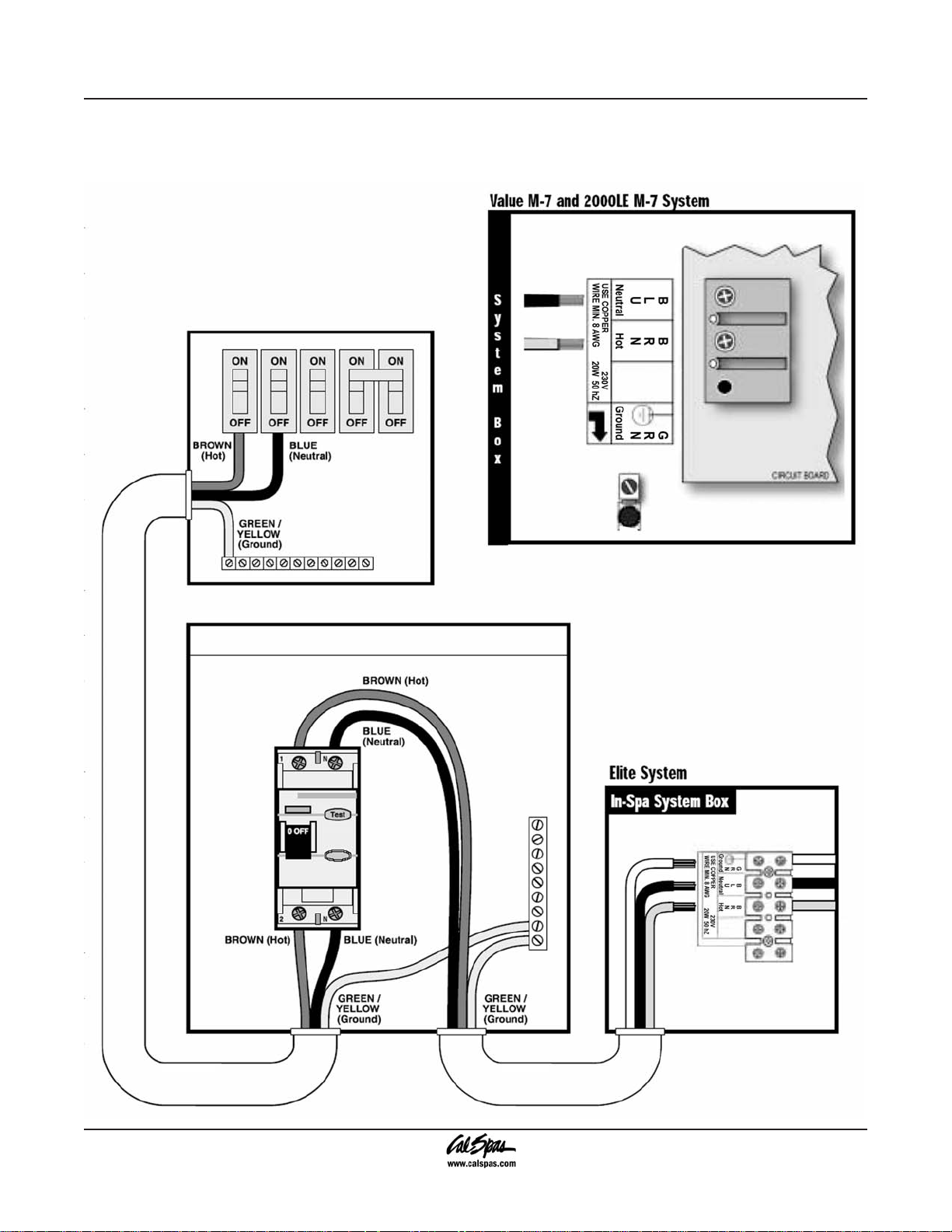
240 Volt Electrical Installation
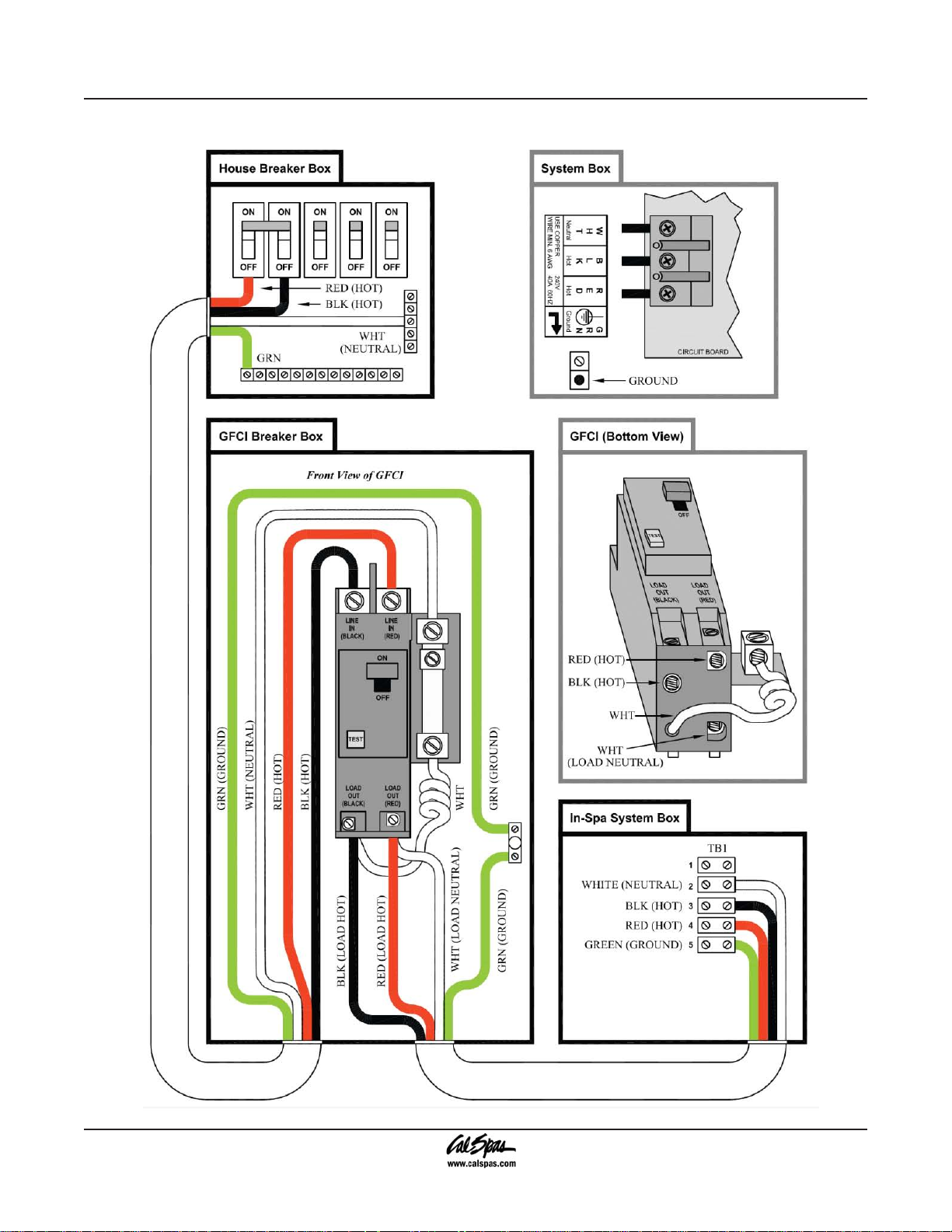
All 240V spas must be permanently connected (hard
wired) to the power supply. These instructions describe
the only acceptable electrical wiring procedure. Spas
wired in any other way will void your warranty and may
result in serious injury. See the wiring diagram on page
8.
When installed in the United States, the electrical wiring
of this spa must meet the requirements of National
Electric Code, ANSI/NFPA 70-2008 and any applicable
local, state, and federal codes. The electrical circuit must
be installed by an electrical contractor and approved by
a local building / electrical inspector.
GFCI and Wiring Requirements
The power supplied to the spa must be on a dedicated
GFCI protected circuit as required by ANSI/NFPA 70
with no other appliances or lights sharing the power.
Use copper wire with THHN insulation. Do not use
aluminum wire.
Use the table below to determine your GFCI and wiring
requirements.
When NEC requires the use of wires larger than #6
AWG, install a junction box near the spa and use #6
AWG wire between the junction box and the spa.
Wire runs over 85 feet must increase wire gauge to the
next lower number. For example: A normal 50 amp GFCI
with four #8 AWG Copper wires run over 85 feet would
require you to go to four #6 AWG copper wires.
Read and follow the heater manufacturer’s safety and
installation instructions prior to installation and operation.
Incorrect installation may damage the heater and void
its warranty.
Testing the GFCI Breaker
Test the GFCI breaker prior to rst use and periodically
when the spa is powered. To test the GFCI breaker
follow these instructions (spa should be operating):
Press the TEST button on the GFCI. The GFCI will
1.
trip and the spa will shut off.
Reset the GFCI breaker by switching the breaker
2.
to the full OFF position, wait a moment, then turn
the breaker back on. The spa should have power
again.
Spa Model GFCI Required Wires Required
Designer in-ground spas
with one 5.5 kW heater
Designer in-ground spa
with two 5.5 kW heaters
One 50 amp GFCI Four #8 AWG copper wires
Service 1: One 50 amp GFCI
Service 2: One 30 amp GFCI
Service 1: Four #8 AWG copper wires
Service 2: Three #8 AWG copper wires
2008 Inground Spa Owner’s Manual Page 7
LTR20081002, Rev. A
Preparing for Your New Inground Spa
GFCI Wiring Diagram
Page 8 2008 Inground Spa Owner’s Manual
LTR20081002, Rev. A
Electrical Installation -- Europe
230 Volt Electrical Installation
All 230V spas must be permanently connected (hard
wired) to the power supply. These instructions describe
the only acceptable electrical wiring procedure. Spas
wired in any other way will void your warranty and may
result in serious injury.
This the only acceptable electrical wiring procedure.
Spas wired in any other way will void your warranty. See
the wiring diagram on page 10.
The electrical wiring of this spa must meet the
requirements of any applicable local, state, and federal
codes. The electrical circuit must be installed by an
electrical contractor and approved by a local building /
electrical inspector.
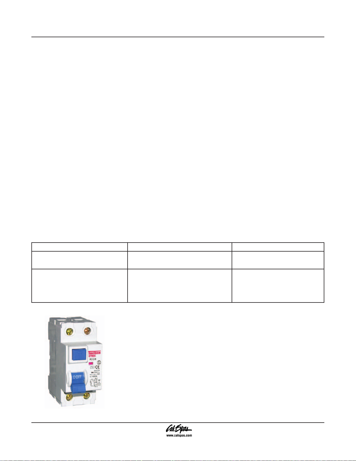
RCD and Wiring Requirements
The power supplied to the spa must be on a dedicated
RCD protected circuit with no other appliances or lights
sharing the power.
Use copper wire with THHN insulation. Do not use
aluminum wire.
Preparing for Your New Inground Spa
When wires larger than #6 AWG are required, install a
junction box near the spa and use #6 AWG wire between
the junction box and the spa.
Wire runs over 85 feet must increase wire gauge to the
next lower number. For example: A normal 50 amp RCD
with four #8 AWG copper wires run over 85 feet would
require you to go to four #6 AWG copper wires.
Testing the RCD Breaker
Test the RCD breaker prior to rst use and periodically
when the spa is powered. To test the RCD breaker follow
these instructions (spa should be operating):
Press the TEST button on the RCD. The RCD will
1.
trip and the spa will shut off.
Reset the RCD breaker by switching the breaker
2.
to the full OFF position, wait a moment, then turn
the breaker back on. The spa should have power
again.
Use the table below to determine your GFCI and wiring
requirements.
Spa Model GFCI Required Wires Required
Designer in-ground spas with one 3
kW heater
Designer in-ground spa with one 3
kW heater and one 5.5 kW heater
One 32 amp RCD or two 16 amp
RCDs
Service 1: One 32 amp RCD or two 16
amp RCDs
Service 2: One 32 amp RCD or two 16
amp RCDs
Four #10 AWG copper wires
Service 1: Four #10 AWG copper
wires
Service 2: Three #10 AWG copper
wires
2008 Inground Spa Owner’s Manual Page 9
LTR20081002, Rev. A
Preparing for Your New Inground Spa
RCD Wiring Diagram
Page 10 2008 Inground Spa Owner’s Manual
LTR20081002, Rev. A
Installing the In-ground Shell
Preparing for Your New Inground Spa
2008 Inground Spa Owner’s Manual Page 11
LTR20081002, Rev. A
Preparing for Your New Inground Spa
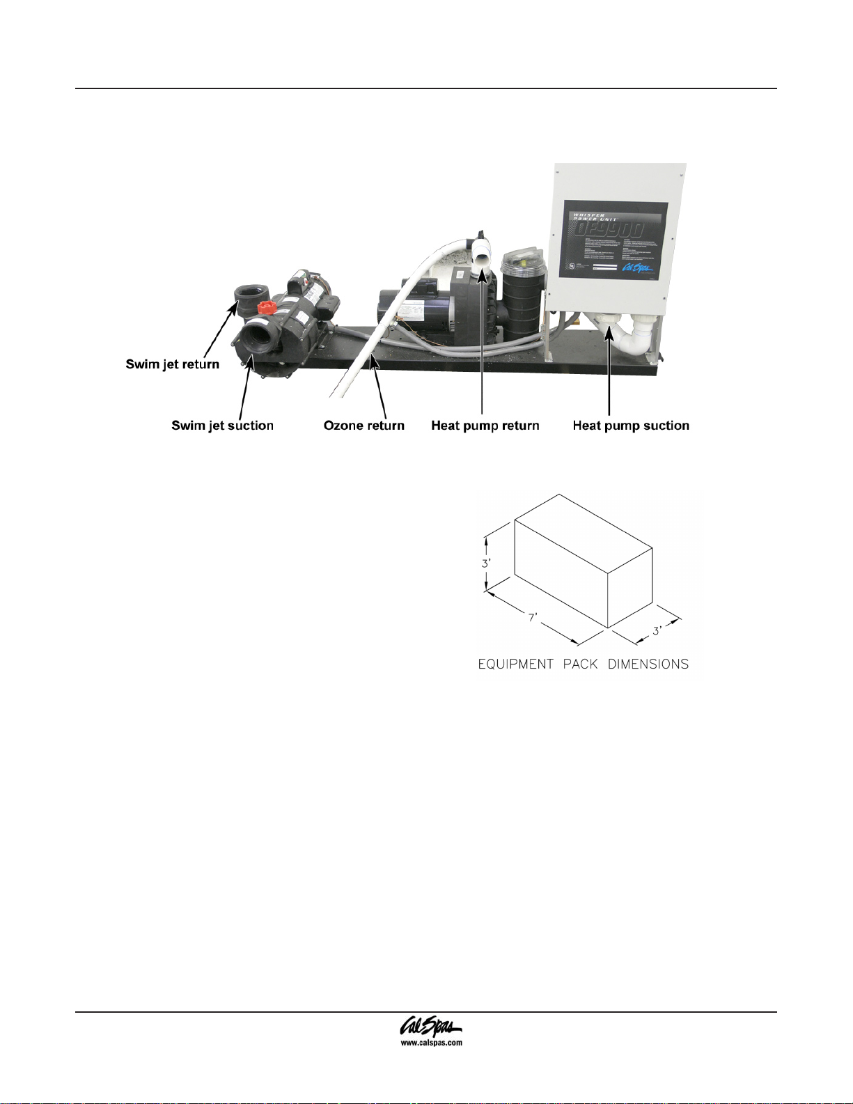
Equipment Pack Plumbing Connections
The example shown below is typical for a system with two pumps with external heater and external lter.
Designer Spa Specications
DIJ401 – DIJ406:
Equipment pack weight = 250 lbs.
DIJ407:
Equipment pack weight = 300 lbs.
One 2.5 HP heat pump
One 4 HP swim pump
Note: Equipment pack cannot exceed 15 feet from spa.
Plumbing Connections
IMPORTANT! Always check local codes prior to any inground spa installation.
Once the spa and equipment are properly located, you
will want to lay out the plumbing run.
Trenches should be deep and wide enough to allow all
pipes to be buried below the frost line and should be in as
straight a line from the spa to the equipment as possible.
Check local code requirements for underground pipes.
Always know what is under the ground before you dig
anywhere.
You will need 2” ex or PVC lines for your suction,
intake, and air line. In ground spas have marked intake
and suction lines, making it easy nd and connect to and
from the spa and equipment pack.
The plumbing run should not be any longer than 15 feet
to maximize water pressure. Another way to maximize
water pressure is to limit (or even eliminate) the use of
90˚ elbows in your plumbing run. A more direct plumbing
run using 45˚ elbows is more efcient, and promotes
increased water pressure.
Identifying Plumbing Lines
The spa’s plumbing lines are clearly marked during
water testing at the factory. This is done to assist
installers in properly identifying the installation. We still
recommend that the installers verify plumbing lines prior
to gluing. This can be done by using one of the following
techniques.
Page 12 2008 Inground Spa Owner’s Manual
LTR20081002, Rev. A

Air Test
The air test requires a wet/dry vacuum.
Locate the plumbing line you wish to
identify and secure the vacuum hose
to cut open end. Turn on the vacuum,
enter the spa and listen for vacuum
suction sound from inside the spa side
lter canister. If you hear the suction
sound in the canister, the line is
properly marked and can be connected
to the suction side of the pump on the
equipment pack.
Water Test
The water test requires a garden hose
and water source. Locate the plumbing
line you wish to identify and secure the
outlet side of the garden hose to cut
open end. Turn on the water supply
to the garden hose, enter the spa and
look for water inside the spa side lter
canister. If you see water in the canister
the line is properly marked and can be
connected to the suction side of the
pump on the equipment pack.
Preparing for Your New Inground Spa
If any plumbing line is not properly
marked or not marked at all, follow
either the air or water test procedure
until all lines are identied prior to
gluing.
NOTE: Once complete, water test the
plumbing run for at least three days
prior to covering any plumbing trenches
and back-lling spa cavity completely.
NOTE: Some local inspectors require
pressure testing the plumbing lines.
Although the spa is pressure tested at
the factory, local inspectors may insist
on pressure testing the plumbing run
between the spa and equipment pack.
Gate/Slice Valves
The use of gate valves is recommended on all plumbing
lines (both suction and return lines). These valves are
used to contain the spa’s water in either the equipment
or the spa. This will assist in the pump priming process
and future servicing without needing to drain the spa.
NOTE: When draining the spa to perform maintenance,
always close the gate valves prior to draining. This will
maintain the pumps prime.
Connecting Plumbing to Remote
Equipment
Connecting the plumbing from the spa to the equipment
pack must be performed in accordance to local and city
codes.
NOTE: Most codes require plumbing to be rigid PVC
schedule 40 or heavier in both above and below
ground installations. In most cases, the use of exible
2008 Inground Spa Owner’s Manual Page 13
LTR20081002, Rev. A

Preparing for Your New Inground Spa
PVC plumbing is acceptable when properly buried in
trenches.
Most water plumbing lines are 2” or larger and must be
schedule 40 or heavier PVC. When plumbing, minimize
the use of 90˚ elbows as much as possible. The use of
45 ˚ elbows will increase the amount of jet pressure you
will have over the use of 90˚ elbows.
The plumbing on the spa shell is labeled by the factory
in the following manner:
Pump 1 Suction: 2” line that connects the spa lter and
bottom drain assembly to the front of pump 1.
Pump 1 Return: 2” line that connects the top of pump 1,
through the equipment lter and heater back to selected
jets in the spa.
Pump 2 Suction: 2” line that connects the spa lter and
bottom drain assembly to the front of pump 2.
Pump 2 Return: 2” line that connects the top of pump 2
back to selected jets in the spa.
Ozone Line: 1” line that connects to a 1” exible line
extending off the bottom of the equipment pack lter
canister through an ozone injector (If ozone equipped)
and connected to ozone port on the spa.
Air Blower: 1 1/2” line that is plumbed out of the air blower
(located on the equipment pack) and extended up 18”
above the spas water level to prevent water ooding the
air blower.
Air Venturi: 1/2” line that is plumbed 18” above the spa’s
water level.
Topside Control Panel and Temp Sensor: 1” line that
connects to the bottom of the control box located on the
equipment pack.
Electrical and Electronic Connection
Remote Equipment Topside Control Panel
The next few steps to complete the installation should
be performed along with installation of the temperature
sensor and 12V spa light wiring (if applicable). All of
these components are generally installed using the
same conduit.
Locate the topside control panel extension loom in
1.
the control box mounted with the equipment pack.
This extension loom and attached black terminal
connector (see gure at right) will be used to connect
the topside control panel to the control box.
Connect one end of the black terminal connector to
2.
the topside control panel cable.
Connect the other end of the terminal connector to
3.
the extension loom.
NOTE: This connection must be kept dry. We recommend
that a waterproof junction box be used in installations
where moisture could penetrate this terminal connector.
Lay out the extension loom to verify that you have
4.
enough length to reach the control box. Remember
that conduit runs are not generally run in a straight
line. Every bend, and up and down run consumes
line length. Take this into consideration when
verifying electrical and plumbing runs.
Connect the extension loom to the control panel
5.
location on the circuit board located inside the
control box. You will also need to connect both the
temperature and high limit sensors to the circuit
board prior to testing. (See the temperature and
high limit installation instruction on the next page
for proper identication and see the wiring diagram
on the inside cover of the control box for proper
placement.)
Turn on the power supply to the spa equipment and
6.
briey test all functions on the topside control panel
to verify that both connections and extension loom
are in working order before proceeding with the
installation.
NOTE: Circuit board programming will not allow spa
operation without both the temperature and high limit
sensors being properly connected to the circuit board.
Once topside panel operation is veried. Turn off
7.
power, disconnect the extension loom from the
circuit board and GENTLY route through conduit to
complete installation.
NOTE: This loom and its connector are not meant to
withstand heavy pulling. Make sure, when routing the
extension loom and temperature sensor lines through
conduit, you exercise extreme caution.
Once properly run through the conduit, repeat steps 5
and 6 above.
In-Ground Spa Light Installation
Instructions
On spas ordered with in-ground lights, the factory installs
the light niche for you. The next steps of installation
should be performed by a qualied licensed electrician.
Always read and follow light manufacturer’s safety and
installation instructions prior to installation and operation.
Page 14 2008 Inground Spa Owner’s Manual
LTR20081002, Rev. A

Preparing for Your New Inground Spa
Incorrect installation may damage the light and void its
warranty.
The light circuit must be on a GFCI protected service
(alone or with a switch). The water resistant junction box
must be located a minimal 8” above water level and 48”
away from the spa. (See gure below.)
Light niche and any metallic items in a 5’ radius must be
properly bonded with #8 AWG grounding wire.
Refer to the gure on the next page for wiring
instructions.
Connect conduit to 3/4” hub located at the back of
1.
the light niche and run to a water resistant junction
box no further than 25’. Remember this is a water
cooled light, so conduit and all connections must be
leakproof.
Feed light cord through conduit to junction box,
2.
leaving at least 4 inches of cord at the end of the
light xture. This slack in the light cord will allow
servicing without draining the spa in the future.
Wrap light cord slack around back of light housing
3.
and attach light to niche with mounting screw.
Run light supply wires in conduit from spa control
4.
box (on equipment skid) to water resistant junction
box.
Connect power supply wires to terminal block
5.
labeled 120V inside spa control box.
Move jumper. (See wiring diagram on the inside
6.
cover of the control box for jumper location for 120V
light operation.)
Connect light wire assembly to power supply wires
7.
from the spa’s control box in the water resistant
junction box as mentioned in Step 2.
Test circuit by turning on the GFCI circuit breaker and
pressing the light button on the topside control panel
located on the spa.
Important: Make sure spa light is submerged in at least
18” of water prior to testing.
2008 Inground Spa Owner’s Manual Page 15
LTR20081002, Rev. A

Preparing for Your New Inground Spa
Page 16 2008 Inground Spa Owner’s Manual
LTR20081002, Rev. A

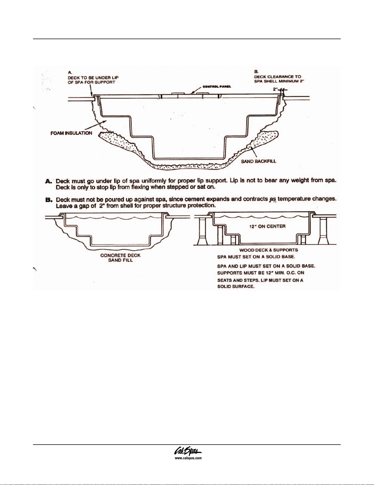
Pouring the Deck
It is recommended that all electrical hook ups and all
plumbing be completed before pouring the concrete.
Make certain all electrical inspections on lights, bonding
and all other electrical work have been completed and
checked off by the local inspectors prior to proceeding
with your concrete or nish work. It is a good idea to run
the spa for at least 24 hours before pouring the concrete
to insure there are no leaks. We understand you want to
enjoy your spa now, but a 24 hour period with your spa
running will let you know of any problems before they
will be extremely hard to x.
The type of decking you have selected will have
determined the grade of the spa. If you are pouring a
regular deck up to the spas coping, then the top of the
coping should be 4” above the surrounding area. In either
event, it is recommended to dig out an area around the
spa exposing the ange of the coping and just under it.
This is important, as concrete should be packed under
and over the ange of the spa, as the deck is poured.
This will lock the spa into the concrete and provide for
a much stronger bond of the spa to the deck. It will also
eliminate cracking of the deck where it meets the spa.
Preparing for Your New Inground Spa
When setting your outside forms, remember you want
any water from rain or splash out to run off the deck, not
into the spa. If your deck is going to tie into an existing
deck, than some type of drain system should be planned
to handle the run off. Proper drainage planning is very
important.
An experienced concrete nisher should always be used
when pouring spa decks, especially when you are doing
a cantilevered deck, as the forms must be taken off at the
proper time to allow nishing of the inside of the form.
2008 Inground Spa Owner’s Manual Page 17
LTR20081002, Rev. A

Operating Your Spa
Operating Your Spa
9800 Electronic Control Operation
When rst powered up, the electronic system
will perform a self-diagnostic check and then
it will automatically heat to and maintain a
temperature of 100°F (37.5°C) until you
change the set temperature as listed in the
“Temperature Adjustment” section below.
These instructions will describe features and options
that your particular spa may not be equipped with.
Initial Start-up
When your spa is rst powered up, it displays some
conguration codes and then goes into priming mode
(Pr will appear on the display panel). This mode lasts up
to four minutes and then the spa begins to heat to its pre
-programmed temperature of 100°F.
Temperature Adjustment
80°F - 104°F (26.0°C - 40.0°C)
The start-up temperature is set at 100°F (37.5°C). The
last measured temperature is constantly displayed
on the control panel. Note that the last measured spa
temperature is displayed. The displayed temperature
will be updated when the pump has been running for at
least two minutes.
Press the “UP” or “DOWN” buttons once to display the
set temperature. Each time either button is pressed
again, the set temperature will increase or decrease
depending on which button is pressed. After three
seconds, the control panel will automatically display the
last measured spa temperature.
Time
When time hasn’t been programmed, the “TIME” icon
ashes. To set the time, press the “TIME” button and
then the “MODE/PROG” button. Use the “UP” and
“DOWN” buttons to adjust time. See the next page for
more detailed instructions.
Standard, Economy, Sleep, and Standby
Modes
Mode/Prog: This button is used to switch between
standard, economy, and sleep modes.
Press “MODE/PROG” to enter mode programming.1.
Press the “DOWN” button to cycle through to the
2.
desired mode.
Press “MODE/PROG” to conrm selection.
3.
Standard Mode: This is programmed to maintain the
desired temperature. Note that the last measured spa
temperature displayed is current only when the pump
has been running for at least two minutes. The “STAND”
icon will display until the mode is changed.
Economy Mode: Economy mode heats the spa to the
set temperature only during lter cycles. The “ECON”
icon will display until the mode is changed. Pressing the
“JETS 1” button while in economy mode puts the spa in
standard-in-economy mode, which operates the same
as standard mode but reverts back to economy mode
automatically after one hour. During this time, pressing
the “MODE/PROG” button will revert to economy mode
immediately.
Sleep Mode: Sleep mode heats the spa to within
20°F (6.7°C) of the set temperature only during lter
cycles. The “SLEEP” icon will display until the mode is
changed.
Standby Mode: Pressing “Warm” or “Cool” then “JETS
2” will turn off all spa functions temporarily. This is helpful
when changing a lter. Pressing any button resets the
spa.
Jets 1 and Jets 2
Press the “JETS 1” button once to turn pump 1 on or off
and to shift between low and high speeds if equipped.
If left running, the low speed turns off after two hours
and the high speed turns off after 15 minutes. On non-
circulation systems, the low speed of pump 1 runs when
the blower or any other pump is on. It may also activate
for at least two minutes every 30 minutes to detect the
spa temperature and then to heat to the set temperature if
needed, depending upon the mode. When the low speed
turns on automatically, it cannot be deactivated from the
panel; however, the high speed may be started.
Page 18 2008 Inground Spa Owner’s Manual
LTR20081002, Rev. A

Operating Your Spa
Option
This is an optional feature. Press the “OPTION” button
to turn the optional equipment on and off. If left on, the
equipment will automatically turn off after 15 minutes.
Light
Press the “LIGHT” button to turn the spa light on and
off and to shift between dim and bright settings if your
light is dimmable. On dim, the control panel will show the
center circle plus one quarter of the light beams. Half of
the light beams will show on medium brightness, and all
of the light beams will show on bright.
Invert
Press the “INVERT” button to change the numbers in the
display to read upside down. Another press returns the
display to the right-side-up position. This enables you to
read the display while you are in the spa.
Locking the Panel
To lock the panel:
Press “TIME”, “JETS 1”, and the “UP” button within
•
three seconds. When locked, the panel will display
“LOCK”. All buttons are frozen except the “TIME”
button.
To unlock the panel:
Press “TIME”, “JETS 1” then the “DOWN” button
•
within three seconds.
Setting the Temperature Lock
To activate the temperature lock:
Press the “UP” or “DOWN” button, “TIME”, “JETS 1”,
•
then the “UP” button within three seconds. The panel
will display “TEMP LOCK” when the set temperature
is locked.
To unlock the set temperature:
Press the “UP” or “DOWN” button, “TIME”, “JETS
•
1”, and then the “DOWN” button.
Circulation Pump
This is an optional feature. The circulation pump will
come on when the system is checking temperature,
during lter cycles, during freeze conditions, or when
another pump is on.
Preset Filter Cycles
There are two lter cycles per day. The start and end
times of each cycle are programmable. To program, set
the time as instructed above, then press “MODE/PROG”
to advance to the next setting (or to exit after the last
setting). The default lter cycles are as follows:
The rst lter cycle is automatically activated at 8:00
•
AM and operates the pump until 10:00 AM. The
“FILTER 1” indicator icon will light when lter 1 is
running.
The second lter cycle is automatically activated at
•
8:00 PM and operates the pump until 10:00 PM. The
“FILTER 2” indicator icon will light when lter 2 is
running.
The pump and the ozone generator will run during
ltration. At the start of each lter cycle, the blower will
run on highest speed for 30 seconds to clean out the
air channels. The lowest speed of pump 2 and pump
3 will run for ve minutes. In the event of power loss or
shut down, the time of day will need to be reset for lter
cycles to run according to your desired programming.
Clean-up Cycle
When the pump or blower is turned on by a button press,
a clean-up cycle begins 30 minutes after the pump or
blower is turned off or times out. The pump and the
ozone generator will run for one hour.
Ozone
This is an optional feature. On most systems, the ozone
generator (if installed) runs during lter cycles (except
when pump 1 is operating at high speed on a non-circ
system) and during clean-up cycles. On some systems,
the ozone generator operates whenever the pump runs.
If your system is congured with the optional ozone
disable feature, the ozone generator will turn off for one
hour any time a function button (“JETS 1”, “JETS 2”,
“OPTION” etc.) is pressed.
Freeze Protection
If the temperature sensors detect a drop to 44°F within
the heater, the pump automatically activates to provide
freeze protection. The equipment stays on until four
minutes after the sensors detect that the spa temperature
has risen to 45°F or higher. In colder climates, an optional
additional freeze sensor may be added to protect against
freeze conditions that may not be sensed by the standard
sensors. Auxiliary freeze sensor protection acts similarly
except with the temperature thresholds determined by
the switch and without a four-minute delay in turnoff.
2008 Inground Spa Owner’s Manual Page 19
LTR20081002, Rev. A
Operating Your Spa
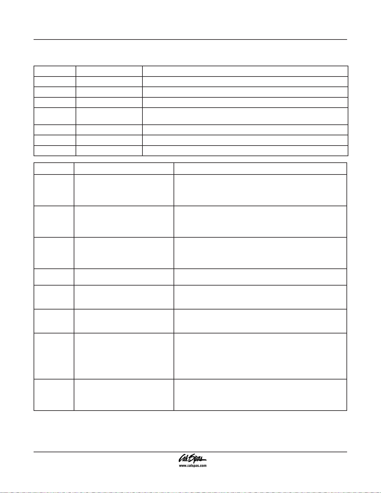
Periodic Reminder Messages
Press the “Mode” button to reset a displayed reminder.
Message Frequency Action Required
rPH
rSA
rCL
rtg
rdr
rCO
rCH
Message Meaning Action Required
OHH
OHS
ICE
Sna
Snb
Sns
HFL
Every 7 days Test and adjust chemical levels per manufacturer’s instructions.
Every 7 days Test and adjust chemical levels per manufacturer’s instructions.
Every 30 days Remove, clean, and reinstall lter per manufacturer’s instructions.
Every 30 days Test and reset GFCI per manufacturer’s instructions. Drain and rell spa
per manufacturer’s instructions.
Every 90 days Drain and rell spa per manufacturer’s instructions.
Every 180 days Clean and condition spa cover
Every 365 days Install New Bio-Clean™ Filter
No message on display. Power has
been cut off to the spa.
“Overheat” - The spa has shut
down. One of the sensors has
detected 118°F at the heater.
“Overheat” - The spa has shut
down. One of the sensors has
detected that the spa water is
110°F.
“Ice” - Potential freeze condition
detected.
Spa is shut down. The sensor that
is plugged into the Sensor “B” jack
is not working.
Spa is shut down. The sensor that
is plugged into the Sensor “A” jack
is not working.
Sensors are out of balance. If this is
alternating with the temperature, it
may just be a temporary condition.
If the display shows only this
message (periodically blinking),
the spa is shut down.
A substantial difference between
the temperature sensors was
detected. This could indicate a ow
problem.
The control panel will be disabled until power returns. Spa
settings and time of day will be preserved for 30 days with
a battery back-up; settings only are preserved until the next
power-up on 7000 systems.
DO NOT ENTER THE WATER. Remove the spa cover and
allow water to cool. Once the heater has cooled, reset by
pushing any button. If spa does not reset, shut off the power
to the spa and call your dealer or service organization.
DO NOT ENTER THE WATER. Remove the spa cover and
allow water to cool. At 107°F, the spa should automatically
reset. If spa does not reset, shut off the power to the spa and
call your dealer or service organization.
No action required. The pumps and the blower will automatically
activate regardless of spa status.
If the problem persists, contact your dealer or service
organization. (May appear temporarily in an overheat situation
and disappear when the heater cools.)
If the problem persists, contact your dealer or service
organization. (May appear temporarily in an overheat situation
and disappear when the heater cools.)
If the problem persists, contact your dealer or service
organization.
If the water level is okay, make sure the pumps have been
primed. If problem persists, contact your dealer or service
organization.
Page 20 2008 Inground Spa Owner’s Manual
LTR20081002, Rev. A

Message Meaning Action Required
LF
dr
dry
Pr
--F or --C
- - - - - -
BUF
Stby
SF
Persistent low ow problems.
(Displays on the fth occurrence
of the “HFL” message within 24
hours.) Heater is shut down, but
other spa functions continue to run
normally.
Inadequate water detected in
heater.
Inadequate water detected
in heater. (Displays on third
occurrence of “dr” message.) Spa
is shut down.
When your spa is rst actuated, it
will go into Priming mode.
Temperature unknown After the pump has been running for two minutes, the
Economy or Sleep mode.
Temperature not displayed.
Internal problem detected. Repair required. Contact your dealer or service organization.
Pressing a button combination
on the user panel has activated
standby Mode.
Safety Suction. Spa is shut down. The display will show “SF” when a vacuum
Follow action required for “HFL” message. Heating capacity
of the spa will not reset automatically; you may press any
button to reset.
Check water level in spa. Rell if necessary. If the water level
is okay, make sure the pumps have been primed. Press any
button to reset.
Follow action required for “dr” message. Spa will not
automatically reset; you may press any button to reset.
The Priming mode will last for up to four minutes and then the
spa will begin to heat and maintain the water temperature in
the Standard mode.
temperature will be displayed.
In Economy or Sleep mode, the pump may be off for hours
outside a lter cycle. If you wish to see the current spa
temperature, either switch to Standard mode or turn Jets1 on
for at least two minutes.
Press any button to leave Standby Mode and return to normal
operation.
switch closes. All functions will turn off and the system will be
disabled until a panel button is pressed.
Operating Your Spa
2008 Inground Spa Owner’s Manual Page 21
LTR20081002, Rev. A

Operating Your Spa
Adjustable Jets
Almost all of the jets in your spa are adjustable. Rotating the face of an adjustable jet to the left (counter-clockwise)
will decrease the amount of water ow through the jet. Rotating the face of an adjustable jet to the right (clockwise)
will increase the amount of water ow through the jet.
NOTE: Neck jets adjust in the opposite directions (counter-clockwise to increase, clockwise to decrease).
Diverter Knobs
Diverter knobs are 1” and 2” knobs located around the
top of your spa. They allow you to divert water through
jets from one side of the spa to the other, or in most
cases from oor jets to wall jets. This is accomplished by
rotating the diverter knob to the left (counterclockwise),
decreasing the amount of water ow through a section
of jets. To increase the amount of water ow through
the other section of jets, rotate the handle to the right
(clockwise).
Air Venturis
Air venturis are the 1” knobs located around the top of
your spa. Each one will let you add a mixture of air with
the jet pressure. This is accomplished by rotating the air
venturi knob to the left (counterclockwise) to increase
the amount of airow through the jets. To decrease the
amount of airow through the jets, rotate the handle to
the right (clockwise).
Page 22 2008 Inground Spa Owner’s Manual
LTR20081002, Rev. A

Operating Your Spa
Removing and Reseating the Pillows
You can remove the pillows for cleaning and maintenance quickly and easily. This method works for all types of
pillows. Grab the lower edge of the pillow with both hands rmly and pull up. As you do this, the pillow inserts will
pop out of the holes.
Reseat the pillows by aligning the pillow inserts with the holes and striking the pillow hard enough to insert the pegs
back into the holes.
Spa Cover
Important! Keep the spa covered when not in use!
Covered spas will use less electricity in maintaining
•
your set temperature.
Covering your spa will protect your spa’s nish from
•
the sun’s ultraviolet rays.
You are required to keep the spa covered to maintain
•
warranty coverage.
Covering your spa helps prevent children from
•
drowning in the spa.
See the manual enclosed with your cover for instructions
on mounting the locks and how to lock and unlock the
cover.
2008 Inground Spa Owner’s Manual Page 23
LTR20081002, Rev. A
In addition, while the spa cover is rigid, it is not designed
to support any weight. Therefore, as a safety precaution
and to preserve the life of your cover, you must not sit,
stand, or lie on it; nor should you place objects of any
kind on top of it.
Waterfalls
Some spa series include optional waterfalls. When the
booster pump is on, turn the knob near the waterfall.
Water will immediately start owing through it.

Cleaning and Maintaining Your Spa
Cleaning and Maintaining Your Spa
Remove the lter basket. With some types you may
Cleaning and Replacing the Filter
Filtration
Filtration is one of the most important steps you can
take to ensure clean, clear water. Regardless of what
some people may think, it is far less expensive to x
water clarity problems by ltering your spa than by using
excessive amounts of chemicals, excessive ltration
times, or by water replacement.
Cal Spas™ ltration system draws contaminated water
through the exclusive Bio-Clean™ lter removing debris
from the water. It then pumps the newly cleaned water
back into the spa through various jets. Spas equipped
with the optional Quest 2000 Ozonator will also receive
ozone injection into the ltered water for further protection
against contaminants during ltration cycles. Filtration
also ensures that chemicals are mixed thoroughly
through the water, increasing performance.
Filtration starts on electronically controlled spas as soon
as the pumps are primed and water ow is steady. As
the ow of water goes through the lter, dirt and debris is
removed and accumulated in the lter cartridge. As the
lter cartridge accumulates dirt and debris, water ow
is restricted and jet performance is reduced. This can
cause your spa to not run or heat effectively.
Clean your lter regularly and replace as needed.
Skimmer Cleaning
The weir skimmer basket helps collect debris in your spa
by trapping oating contaminants. The buoyant skimmer
door opens and closes as needed. A suction pump
pulls water into the weir skimmer and collect debris I
the skimmer basket inside. You will need to clean this
basket periodically to help keep your water clean.
3.
need to align the at areas on the lter basket and
the canister.
Remove the lter by pulling up and out.
4.
Clean the lter with a garden hose as follows:
5.
a.
b.
c.
d.
e.
Exclusive Bio-Clean™ Filter Cartridge
The lter cartridge is designed to remove dirt, sand,
minerals, phosphates, bather waste and other solids from
the spa. Unfortunately, some spa owners fail to include
lter cleaning as part of their chemical maintenance
plan. Filters accumulate debris and become prime areas
for bacteria growth.
The Cal Spas™ exclusive Bio-Clean™ Filter is the only
antibacterial lter cartridge on the market today. Having
a lter cartridge that prevents bacteria growth is added
protection for those times you forget to clean the lter.
We recommend that you only replace your spa’s lter
cartridge with a Bio-Clean™ lter cartridge for ensured
protection and peace of mind.
Hold the lter vertically.
Spray the lter cartridges with a pressure nozzle,
starting from the top and spraying down each
pleat.
Turn the lter cartridge over and repeat Step
5B.
Reinstall the lter cartridge in reverse order of
removal.
Deep clean lter cartridge every month. Use
only a Cal Spas™-approved lter-cleaning
chemical.
Filter Cleaning
Your new Cal Spa has been designed for quick and easy
lter maintenance. The lter cartridge should be cleaned
once a week. These instructions apply to both dual and
single ltration systems.
Turn the power off at the breaker.
1.
Remove the lter cover (if applicable) by rotating the
2.
cover counterclockwise and lifting it off..
Page 24 2008 Inground Spa Owner’s Manual
LTR20081002, Rev. A

Cleaning and Maintaining Your Spa
Cleaning the Cover, Shell and Pillows
Due to the constant punishment your spa cover and
pillows receive, you should protect them by applying
Vinyl and Leather Cleaner as part of your monthly
maintenance plan. Cal Spas™ Vinyl and Leather
Cleaner is specically designed to protect spa covers
and pillows from chemical and ultraviolet light damage. It
accomplishes this without leaving an oily residue behind
that is normally associated with common automotive
vinyl protectants.
Use of Vinyl and Leather Cleaner
Cal Spas™ Vinyl and Leather Cleaner should be used
sparingly. Incorrect usage may cause water clarity
issues.
Spa Covers
Remove spa cover from
1.
spa.
Allow spa cover to dry
2.
completely.
Spray Vinyl and Leather
3.
Cleaner to cover evenly and
wipe dry.
Allow spa cover to dry
4.
completely.
Reinstall cover on spa.
5.
Pillows
Wipe pillows dry with a soft
1.
cloth.
Carefully spray Vinyl and
2.
Leather Cleaner directly
onto pillow.
Wipe pillows dry.
3.
Allow pillows to dry
4.
completely.
All-Purpose Cleaner (Spa nish cleaning)
Cal Spas™ All-Purpose Cleaner is an
essential part of maintaining your spa’s
nish. Through normal use, the spa’s nish
can accumulate dirt, oil, and calcium
causing a rough feel and unsightly scum
lines. Cal Spas™ All-Purpose Cleaner is a
low detergent, non-abrasive cleaner
specically formulated to clean the spa
without damaging its acrylic nish.
The most effective solution to minimize cleaning time
is prevention. When the following steps are followed,
the spa’s nish will actually start to resist most of the
elements that cause calcium build-up and make scum
line clean up easier.
Prior to Spa Start-Up and Relling
Spray Cal Spas™ Multi-Purpose Cleaner directly on
1.
to the spa’s nish.
Wipe clean with a clean soft cloth.
2.
Repeat on heavily calcied areas.
3.
Wipe spa thoroughly with a wet sponge, rinsing
4.
often with a bucket of clean water.
Allow spa to dry completely.
5.
Apply a coat of Cal Spas™ Fast Sheen to the spa’s
6.
entire nish with a soft towel or sponge.
Allow Fast Sheen to dry until white and powdery.
7.
Buff clean with a soft cloth, rotating frequently.
8.
Periodic Maintenance
Spray Cal Spas™ Multi-Purpose Cleaner directly to
1.
the spa’s nish.
Wipe clean with a clean soft cloth.
2.
Wipe spa thoroughly with a wet sponge, rinsing
3.
often in a bucket of clean water.
Cal Spas™ Multi-Purpose Cleaner should not be
sprayed directly into the spa water. Incorrect usage of
this product will cause water clarity issues.
Warning: Do not use automotive vinyl protectants on
spa covers or pillows. These products are generally oilbased and will cause severe water clarity issues that are
difcult to correct.
2008 Inground Spa Owner’s Manual Page 25
LTR20081002, Rev. A

Cleaning and Maintaining Your Spa
Fast Sheen (Spa nish protecting wax)
Cal Spas™ Fast Sheen is an essential
part of maintaining your spa’s nish.
Through normal use, the spa’s nish can
accumulate dirt, oil, and calcium, causing
a rough feel and unsightly scum lines. Cal
Spas™ Fast Sheen is a non-oil based wax
that is specically formulated to protect
the spa’s nish from the chemicals and
minerals associated with normal spa use.
The most effective solution to minimize cleaning time
is prevention. When the following steps are followed,
the spa’s nish will actually start to resist most of the
elements that cause calcium build-up and make scum
line clean-up easier.
Prior to Spa Start-Up and
Relling
Spray Cal Spas™ Multi-Purpose Cleaner directly to
1.
the spa’s nish.
Wipe clean with a soft cloth.
2.
Repeat on heavily calcied areas.
3.
Wipe spa thoroughly with a wet sponge, rinsing
4.
often in a bucket of clean water.
Allow the spa to dry completely.
5.
Apply a coat of Cal Spas™ Fast Sheen to the spa’s
6.
entire nish with a soft cloth or sponge.
Allow Fast Sheen to dry until white and powdery.
7.
Buff clean with a soft cloth, rotating frequently.
8.
IMPORTANT: Cal Spas™ Fast Sheen should not be
used on spas full of water. Only apply to clean, cool,
dry surfaces. Incorrect product usage may cause water
clarity issues.
Filling and Powering Up Your Portable Spa
Never ll your spa with soft water. Soft water makes it
impossible to maintain the proper water chemistry and
may cause the water to foam, which will ultimately harm
the nish of the spa and void your warranty.
Once the spa has been properly installed and
1.
has been correctly wired by a licensed electrician,
inspect all plumbing connections at the equipment
area of your spa. Ensure that these connections are
secure.
If equipped, open all gate valves in the equipment
2.
area. Before operating the spa, these valves must
be in the up or “open” position.
Remove the lter basket and cartridge from skimmer/
3.
lter canister.
Place a garden hose in the skimmer/lter canister
4.
and ll your spa with regular tap water to the proper
water level (halfway up the skimmer area).
Open the air relief valve (located next to the two
5.
lters, if equipped) after the air bubbles stop coming
out of it. Close the valve hand-tight.
Once the water is at the correct level and air is bled,
6.
turn on the power at the GFCI breaker. (Ensure that
the 120V spas are connected to the proper electrical
outlet.)
When the power is turned on to the spa, it will perform
a diagnostic check. When the diagnostic is complete,
the spa will automatically operate at lter speed and
continue heating until the spa water temperature reaches
the default temperature of 100˚F.
If no water is owing when the pump is running
7.
there could be an air pocket at the suction side of
the pump. Shut off power to the spa and loosen the
pump union on the suction side of the pump to bleed
the air. When air is bled, turn power back on.
Re-install the lter and the lter basket into the
8.
skimmer/lter canister.
The spa is now ready for use.
Note: Never run the spa with the gate valves closed or
without water circulating for long periods of time. Be
careful not to over-tighten the plumbing ttings.
Page 26 2008 Inground Spa Owner’s Manual
LTR20081002, Rev. A

Draining Your Spa
Your spa should be drained every four to six months,
and relled with fresh tap water. The following is the
recommended method for draining your spa.
Turn off the power at the breaker.
1.
Remove all lters.
2.
Hook up the female end of a garden hose to the
3.
drain tting (if equipped).
Place the other end of the garden hose where you
4.
would like the water to drain to.
Let spa drain completely, then remove garden hose
5.
and rell.
Winterizing (Cold Climate Draining)
In many areas of the country, the temperature drops
below 32˚F (0°C). We recommend that you always
have your spa full of water and running at normal spa
temperatures (80˚F to 100˚F, 26.7°C to 37.8°C). This will
help reduce the risk of freezing in your spa and your
spa’s equipment.
Cleaning and Maintaining Your Spa
WARNING: If you nd the need to drain your spa,
please be aware of the potential of freezing in your spas
equipment and plumbing. Even if the directions below
are followed perfectly, there is no guarantee that your
spa will not suffer freeze damage and thereby void the
warranty coverage.
Open all lter covers.
1.
Remove the lter baskets and lters.
2.
Drain your spa completely as described in the
3.
instructions above.
Remove drain plugs from the front of the pumps.
4.
Disconnect the unions from both sides of the pump.
5.
Use a wet/dry vacuum to blow any remaining water
6.
out of the jets and equipment area.
Cover your spa with a good spa cover and an all-weather
tarp to ensure that neither rain nor snow enters the spa.
2008 Inground Spa Owner’s Manual Page 27
LTR20081002, Rev. A

Water Quality Maintenance
Water Quality Maintenance
Great spa water is easily achieved when the right
chemicals and / or systems are used and the Cal Spas
“Clear Water Plan” is implemented. The key to clean,
clear, and safe water is to fully understand how spa
water reacts to users, system operation and chemical
use. The “Clear Water Plan” will help give you that
understanding.
The rst thing to understand about taking care of your
spa water is that preventive actions are much easier to
do than correcting water quality issues. For this reason,
we offer the “Clear Water Plan” as a simple, easy to
follow guide to clean, safe spa water.
Follow the Right Plan
You will need to decide which chemical plan or alternative
sanitation option works best for your spa water. Consult
your Cal Spas dealer for the right decision with regards
to your lifestyle and spa usage. Whichever plan you
decide on, follow it completely and don’t take shortcuts.
These plans will provide you with clean, safe, clear spa
water with a minimum of effort.
Traditional Chemical Options
Choose from either Bromine tablets or Chlorinating
granules as your sanitizer of choice. Both work well
when the appropriate “Clear Water Plan” is followed.
Make sure you follow all instructions and use only Cal
Spas brand chemicals.
Before You Begin
Before you begin a “Clear Water Plan”, you should
understand that chemicals or systems alone will not take
care of your spa water. Other factors such as Filtration
and Bather Load also play an important part.
Filtration
The lter is the part of your spa that removes the debris
from the water. Even though Cal Spas uses the advanced
Bio Clean lter cartridge that protects itself from bacterial
growth, the lter still needs to be cleaned on a regular
basis to maximize your spa’s ltering performance and
heating efciency.
In addition to spraying off the lter weekly to remove
surface debris, your lter should be deep cleaned
periodically to dissolve scale and other contaminants
that get lodged deep within the lter bers and impede
the ltration process. Even if the lter looks clean, the
contaminants can clog the bers and prevent water from
owing through the lter resulting in the most common
spa problem—no heat, caused by a dirty lter.
Filter Cleaning
Place the dirty lter into a bucket of water deep enough
to cover the lter. Add 8oz of Cal Spas “Liquid Filter
Cleaner” to the bucket of water.
Note: It is a good idea to keep a spare lter to be deep
cleaned while the regular lter is in the spa. This way,
you can rotate the lters and both will last longer.
Soak the lter for a minimum of 24 hours.
Remove the lter and spray clean with a water hose.
Spray each pleat carefully.
Allow lter to dry completely (a minimum of 2 days drying
time is recommended).
Reinstall lter as described in the “Clear Water Plan”.
Filtration Cycles
The ltration cycle of your spa is the process that allows
the water to ow through the lter. Your spa will lter
automatically twice each day. The factory set default time
for ltration is usually enough for normal use, however
heavy bather load or frequent use may require longer
ltration times or more frequent ltration cycles to keep
the spa water clean. Consult your Owner’s Manual for
setting your spa’s ltration times.
Bather Load
“Bather Load” is the term used to describe the number of
people using a spa, combined with the length of usage,
and the frequency of usage. All these factors have a
great effect on the spa water. The higher the bather
load, the more chemicals need to be added and a longer
ltration time will be needed.
All versions of the Cal Spas “Clear Water Plan” are
designed for spas with average bather load. (3-4 people,
15 minutes of usage, 3 times a week at 100 degrees)
If your bather load exceeds these guidelines, and you
experience water quality problems, increase the amount
of ltration rst, (go to the next higher ltration number)
then if water quality is still not adequate, consult the
advise of your Cal Spas dealer for additional chemical
or system recommendations. Be sure to give them your
bather load information.
Page 28 2008 Inground Spa Owner’s Manual
LTR20081002, Rev. A

Chemical Overview
The following information is intended for use with Cal
Spas chemicals only. Other brands of chemicals may
have similar names and/or usage descriptions but due
to manufacturing differences, use of other chemicals
can increase the likelihood of under or over-dosing the
spa chemicals. Damage to the spa or spa’s components
from improper chemicals or chemical usage is not
covered under the spa’s warranty.
Chemical Safety
Failure to follow chemical directions may result in
•
serious injury, sickness, or even death.
Read and follow all printed instructions listed on
•
bottles, packages and in your owner’s manual.
Do not exceed chemical dosages as recommended
•
in the “Clear Water Plan”, or on chemical bottles and
packages. (Most chemical instructions are gured
for a 500 gallon spa however, most spas hold less
than 500 gallons, consult your Owner’s Manual for
the approximate gallons of your spa)
Never mix chemicals together.
•
Never change chemical brands or types without
•
completely draining, ushing and thoroughly
cleaning the spa and cover rst.
Always protect your eyes while introducing chemicals
•
into the spa. Wear protective eyeglasses to prevent
powdered chemicals from blowing into the eyes or
liquid chemicals from splashing into the eyes.
Water Quality Maintenance
In the event of overdosing a sanitizing chemical
•
(chorine or bromine), immediately turn off the power
to the spa and drain water to a safe and approved
area. Rell with fresh water and proceed with the
“Clear Water Plan” start up.
Physical Chemical Hazards
Do not allow chemicals to come in contact with skin,
•
eyes or clothing.
Always wear rubber gloves, protective eye wear and
•
clothing to reduce the risk of chemical contact and
irritation.
Remove and wash clothing that may have been
•
exposed to chemical contact prior to wearing them
again.
Inhaling or ingesting chemicals will cause serious
•
injury, sickness, or even death.
Do not mix chemicals. Mixing chemicals together
•
can cause dangerous chemical reactions including
the release of toxic gas, re and explosions.
Chemical Storage
Chemicals must be stored completely out of the reach
of children in an area that is well vented, cool, and dry.
Failure to provide a proper area for chemical storage
may result in serious injury, sickness, re explosion
and even death. Do not store your chemicals inside the
equipment area of your spa.
2008 Inground Spa Owner’s Manual Page 29
LTR20081002, Rev. A

Water Quality Maintenance
Chemical Descriptions
The following descriptions and recommendations are intended for use with Cal Spas chemicals only. Many of these
chemicals will be used with alternative sanitation systems as well.
For use with any Clear Water Plan
Oxidizer Shock
Destroys
ammonia, organic
contaminants, and
odor causing wastes
in spa water.
Ph / Alkalinity Up
Raises pH and alkalinity
levels in spa water.
Iron Out
Helps prevent metals in
water from staining spa.
Use during start up.
Ph / Alkalinity Down
Lowers pH and alkalinity
levels in spa water.
Stain and Scale Defense
Helps prevent minerals
from damaging spa
components.
Liquid Hardness
Increaser
Helps reduce foaming and
corrosion by increasing
hardness levels in spa
water.
Spa Brite
Helps to quickly clear up cloudy spa water.
Filter Cartridge Cleaner
Deep cleans lter cartridge. Dissolves scale
and removes imbedded organic contaminants
from lter cartridge bers.
Page 30 2008 Inground Spa Owner’s Manual
LTR20081002, Rev. A
Foam Gone
Quickly breaks up existing foam on spa water.
Enzyme Formula
Biodegrades body oils, suntan lotions, and
organic contaminants in spa water. Do not use
on same day as adding Chlorine Granules.

For use with the chlorine Clear Water Plan
Water Quality Maintenance
Chlorinating Granules
Quick acting sanitizer / disinfectant for spa
water.
For use with the bromine Clear Water Plan
Test Strips -- Bromine
Provides accurate
spa water testing for
bromine, pH, and total
alkalinity.
Go Brom
Establishes a bromide
reserve in spa water.
Use during start up.
Test Strips – Chlorine
Provides accurate spa water testing for
bromine, pH, and total Alkalinity.
Brominating
Tablets
Long lasting sanitizer
/ disinfectant for spa
water. Add to bromine
oater.
For use with the Cal Clarity Bromine Generator
Test Strips -- Sodium Bromide
Provides accurate spa water testing for sodium bromide.
2008 Inground Spa Owner’s Manual Page 31
LTR20081002, Rev. A

Water Quality Maintenance
Traditional Chemical Start Up
Prior to lling a spa for the rst time, or after a routine
draining, you will want to follow this start-up plan to
extend water life and performance. If you are following
either the Bromine or Chlorine “Clear Water Plans”, you
will notice that both start-up processes are the same with
the exception of Step 7. As with all chemical dosages
listed in these “Clear Water Plans”, start-up dosages are
intended for 500-gallon spas. Please adjust the chemical
dosages to the capacity of your particular spa.
Clean surface of spa with Cal Spas “Multi-Purpose
1.
Cleaner”.
Apply a protective coat of Cal Spas “Fast Sheen” to
2.
the acrylic surface.
Fill spa to proper water level with normal tap water
3.
(Do not use soft water)
Use test strip and balance the spa water:
4.
Adjust total alkalinity (acceptable range is 80-
5.
120ppm),
Pour in 16 oz of Cal Spas “Metal Protector” to center
7.
of spa.
Add either Bromine or Chlorine (According to your
8.
preferred plan)
Bromine:
Add 2 oz of Cal Spas “Go Brom” to establish a
bromine base.
Add 2 Cal Spas “Bromine Tablets” to Bromine
Floater.
Set oater opening at #2.
Chlorine:
Add two tablespoons of Cal Spas “Chorine
Granules” to the spa water.
Sprinkle 2 oz of Cal Spas “Oxidizer Shock” in the
center of the spa and turn on jets for 15 minutes.
Leave spa uncovered during this time.
Put cover on spa and allow to heat up to desired
9.
temperature.
Then adjust pH if necessary. (between 7.2 to 7.8)
6.
Page 32 2008 Inground Spa Owner’s Manual
LTR20081002, Rev. A

Water Quality Maintenance
Bromine Clear Water Plan
This plan and its chemical dosages are intended for Cal
Spas chemicals only. Most chemical manufacturers use
different chemical formulas and strengths. Only Cal spas
chemicals are specially formulated to provide chemical
balance at lower dosages. Always read and follow printed
instructions on chemical bottles and packages.
Day One (Monday)
Test spa water using “Bromine Test Strips”.
1.
Based on the Test Strip readings:
2.
Adjust total alkalinity rst (acceptable range of
•
80-120 ppm)
Then adjust the pH if needed. (range is between
•
7.2 to 7.8)
Add “Bromine Tablet(s)” if needed. (Do not add
•
more than 2)
The recommended level of bromine is 3-5 ppm.
•
Add 2 oz of “Stain and Scale Defense”.
3.
Remove dirty lter from the spa and rinse off. Allow
4.
to dry.
Place your extra clean lter cartridge back into the
5.
spa.
Vacuum debris from the bottom of your spa with the
6.
“Spa Vacuum”.
Day Two (Wednesday)
Test spa water using Bromine Test Strips.
1.
Based on the Test Strip reading: Adjust total alkalinity,
2.
then the pH if needed.
Day Three (Friday)
Test spa water using Bromine Test Strips.
1.
Based on the Test Strip reading:
2.
Adjust total alkalinity, then the pH if needed.
•
Add one Bromine Tablet (if needed).
•
Chlorine Clear Water Plan
This plan and its chemical dosages are intended for Cal
Spas chemicals only. Most chemical manufacturers use
different chemical formulas and strengths. Only Cal spas
chemicals are specially formulated to provide chemical
balance at lower dosages. Always read and follow printed
instructions on chemical bottles and packages.
Day One (Monday)
Test spa water using “Chlorine Test Strips”.
1.
Based on the Test Strip readings:
2.
First adjust total alkalinity (acceptable range of
•
80-120 ppm)
Then adjust the pH if needed. (range is between
•
7.2 to 7.8)
Add 2 tablespoons of Chlorine Granules.
•
The recommended level of Chlorine is 3-5
•
ppm.
Add 2 oz of “Stain and Scale Defense”.
3.
Remove dirty lter from the spa and rinse off.
4.
Place your extra clean lter cartridge back into the
5.
spa.
Vacuum debris from the bottom of your spa with the
6.
“Spa Vacuum”.
Day Two (Wednesday)
Test spa water using Chlorine Test Strips.
1.
Based on the Test Strip reading: Adjust total alkalinity,
2.
then the pH if needed.
Day Three (Friday)
Test spa water using Chlorine Test Strips.
1.
Based on the Test Strip reading:
2.
Adjust total alkalinity, then the pH if needed.
•
Add 2 tablespoons of Chlorine Granules. (if
•
needed)
Add 2 oz of Oxidizer Shock to spa. Run Spa for 15
3.
minutes with cover off.
Replace cover.
4.
2008 Inground Spa Owner’s Manual Page 33
LTR20081002, Rev. A
Add 2 oz of Oxidizer Shock to spa. Run Spa for 15
3.
minutes with cover off.
Replace cover.
4.

Water Quality Maintenance
Del Zone Eclipse Ozonator
This plan and its chemical dosages are intended for
spas equipped with the Del Zone Eclipse. The chemical
references are designed for Cal Spas chemicals only.
Start Up
Follow the Spa Start Up procedures for Chlorine
1.
“Clear Water Plan”.
Set the spa’s ltration time for “F-4”. This activates
2.
the ozonator and produces the ozone gas. (Follow
the instructions in the owner’s manual)
Note: Filtration time may need to be increased with
heavy bather load.
Day One (Monday)
Test spa water using chlorine “Test Strips”. (you
1.
will need to use a small amount of chlorine as a
supplemental sanitizer)
Based on the Test Strip readings:
2.
First adjust total alkalinity (acceptable range of
•
80-120 ppm),
Then adjust the pH if needed. (range is between
•
7.2 to 7.8)
Add 1 tablespoon of Chlorine Granules.
•
The recommended level of Chlorine is 1-3
•
ppm.
Add 2 oz of “Stain and Scale Defense”.
3.
Remove dirty lter from the spa and rinse off.
4.
Place your extra clean lter cartridge back into the
5.
spa.
Vacuum debris from the bottom of your spa with the
6.
spa vacuum.
Day Two (Friday)
Test spa water using Chlorine Test Strips.
1.
Based on the Test Strip reading:
2.
Adjust total alkalinity, then the pH if needed.
•
Add 1 tablespoon of Chlorine Granules. (if
•
needed)
Add 2 oz of Oxidizer Shock to spa. Run Spa for 15
3.
minutes with cover off.
Replace cover.
4.
Maintenance
Regardless of which “Clear Water Plan” you are using,
you should also do the following:
Every Month
Deep clean your spa’s lter. (Follow “lter cleaning”
1.
instruction at beginning of “Clear Water Plan”)
Check inside the equipment area for leaks, rodents,
2.
and insects.
If a leak is discovered, contact your Cal Spas dealer
3.
for service.
If you see evidence of rodents or insects, take
4.
necessary actions to remove them and precautions
to prevent them from returning.
Every 3 To 4 Months
Drain and clean your spa with “Multi-Purpose
1.
Cleaner”.
Polish the acrylic surface with “Fast Sheen”.
2.
Clean and treat spa cover, pillows, and Cal Select
3.
cabinet (if equipped) with “Cover Protector”.
When re-lling your spa, follow your specic “Clear
4.
Water Plan” Start Up procedures.
If you use the Cal Inline Sanitation System “Clear
5.
Water Plan”, don’t forget to replace the Mineral and
Bromine Cartridges.
Once A Year
Clean and treat redwood spa cabinets and gazebos with
“Nu-Spa Redwood Stain Renew and Brightner”.
Check the lter cartridge pleats. If they are frayed,
replace the cartridge.
Page 34 2008 Inground Spa Owner’s Manual
LTR20081002, Rev. A

Appendix
Replacement Parts
Appendix
PLU21700818
OZONE INJECTOR JET`
PLU21703432
(MFW) 3.25”, STORM JET, MICRO
FLOW W/DRK EYEBALL
PLU21703420
(EW) 2” INTERNAL CLUSTER STORM,
PULSATOR (EURO)
PLU21700565
SW, STREAM (SWIM) JET COMPLETE
PLU21703425
(CXW) 5.5”. POWER STORM JET,
DIRECTIONAL
ACC01400864
STD PILLOW, #965 RECTANGULAR
PLU21300062
DIVERTER VALVE 2” (2 WAY) SILVER,
TEARDROP HANDLE (2 TONE)
PLU21700378
VENT, 1” AIR CONTROL SILVER,
TEARDROP (2 TONE)
PLU21400132
MAIN DRAIN, SUPER HI FLO
SUCTION 2” SILVER
Lights
LIT16000100 LIGHT INGROUND 100W 120V 30’
LIT16100153 WALLFITTING, CLEAR LENS CAP, JUMBO SPA LIGHT, 5”
LIT16100155 RED LENS INSERT, JUMBO SPA LIGHT
LIT16100156 BLUE LENS INSERT, JUMBO SPA LIGHT
2008 Inground Spa Owner’s Manual Page 35
LTR20081002, Rev. A

Appendix
Filters
FIL11100125 FILTER CARTRIDGE CAL 75 SQ” 10 1/16 X 15 1/6 (REMOTE EQUIPMENT)
Pumps
PUM22000951 PUMP, 5.0 HP 2 SP SWITCHLESS, DBL SEAL 240V
PUM22000941 PUMP 6.0 HP 2SP 145T DBL SEAL, SWITCHLESS 2” 240V
PUM22000031 PUM 1.5 HP 2 SP 2” WET END 120V -
PUM22000916 PUMP DUALLY, DBL SEAL SWITCHLESS 2” ULTIMA-240V
PUM22000952 PUMP 1.0 HP ATS – 240V
PUM22200051 PUMP, 1.5 BHP DUALLY GE-56 FRAME, DBL SEAL-120V
PUM22000075 DYNA-MAX PUMP, 2.5 HP 2 SPEED 240V
PUM22000745 PUMP, SPECK 4 HP 2 SP W/O TRAP 240V
PUM22000802 PUMP 5BHP 2 SPEED INTERNATIONAL 50 HZ 230V
PUM22000977 24 HOUR FILTRATION PUMP ASSEMBLY 240V
PUM22100944 SPA CAL FILTRATION CIRC PUMP 240V
PUM22000973 24 HOUR FILTRATION PUMP ASSY INTERNATIONAL 50 HZ 230V
PUM22000531 SPA CAL FILTRATION CIRC PUMP INTERNATIONAL 50 HZ 230V
BLO05000085 BLOWER W/CORD COMPLETE 1.5 HP 240V 3.5 AMPS
PLU21100160 CHECK VALVE 1 ¼ lb.
Cover Lifts
ACC01600116 COVER LIFT KIT, BOTTOM MOUNTING
ACC01600117 COVER LIFT ADJUSTABLE(top mount)
Hand Rails
FIX12400002 SWIVEL HAND RAIL
FIX12400003 SWIVEL HAND RAIL (BLACK)
Filter Lids
FIL11300252 FILTER LID, DUAL
FIL11300253 FILTER LID, SINGLE
Covers
RUST GREY SLATE
DIJ-401 – 93” ROUND ACU02200311 ACU02200310 ACU02200315
DIJ-402 - 93 OCTOGON ACU02200331 ACU02200330 ACU02200332
DIJ-403 - 93 x 93 ACU02200551 ACU02200550 ACU02200552
DIJ-404 - 93 x 130 ACU02200343 ACU02200339 ACU02200344
DIJ-405 - 93 x 130 ACU02200541 ACU02200540 ACU02200542
DIJ-406 - 80 x 120 ACU02200341 ACU02200340 ACU02200348
DIJ-407 - 93 x 200 ACU02200301 ACU02200300 ACU02200305
Page 36 2008 Inground Spa Owner’s Manual
LTR20081002, Rev. A

Appendix
Keeping Fit with your Cal Spa
IMPORTANT: Always consult your physician before starting any exercise activity or program. The tness series
spas feature rubber exercise bands. When stretched, these bands create a high tension condition. Improper use or
failure to connect the exercise bands properly may cause injury. Always inspect all of the exercise equipment prior
to beginning any exercise. Do not use any damaged equipment
The tness equipment consists of: two rowing arm bars, two 62” exercise bands, two 32” exercise bands, two 27”
exercise bands, two hand grips, two ankle bands, two hand loops, and an exercise belt. This equipment attaches
to the exercise anchors located on the spa walls.
Fitness Series™ Exercise Program
Refer to the equipment congurations shown on the next page for the following exercises.
Seated Row
Use the exercise bars in a seated position with your
feet stable, abs tight and lower back stable. Keep your
palms down, arms extended with elbows slightly bent.
Pull towards your chest squeezing your shoulder blades
to the middle back and returning slowly to the starting
position.
Standing Chest Fly
Using the exercise grips, place palms sideways facing
your body with your elbows slightly bent. Pull forward
your body forward, bringing hands together, squeezing
and exing chest muscles, then slowly returning to the
starting position.
Standing Chest Press
Using the exercise grips, place your palms down with
your elbows bent at 90˚. Press forward bringing your
hands together, squeezing and exing your chest
muscles, then slowly return to the start position.
Standing Shoulder Press
Using the exercise grips, place your palms facing away
from your body with your elbows bent at 90˚. Press
upward bringing your hands together in front of you,
above your head and slowly return to the start position.
Arm Curls
Using the exercise grips, place your hands face up with
your elbows slightly bent, pull upward towards your chin
squeezing and exing your biceps then slowly return to
start position.
Running or Walking
Attach the exercise belt around your waist and attach the
two 62” exercise bands to the far wall of the spa. Turn on
the two swim jets and walk or run into jet stream.
Leg Streching and Strength Training
Attach an ankle band to your ankle and attach a 62”
exercise band to any exercise anchor. Lift your leg to the
side or back as the band provides tension.
2008 Inground Spa Owner’s Manual Page 37
LTR20081002, Rev. A

Appendix
Connecting the Exercise Equipment
The drawings below show different ways the exercise
kit can be connected depending on the exercises you
wish to do.
Page 38 2008 Inground Spa Owner’s Manual
LTR20081002, Rev. A

Cal Spas™ Chemicals
Appendix
2008 Inground Spa Owner’s Manual Page 39
LTR20081002, Rev. A

C.A.I. Customer Service Department
1462 East Ninth Street
Pomona, CA 91766
Toll Free: 1-800-CAL-SPAS
Fax: 1-909-629-3890
www.calspas.com
LTR20081002, Rev. A
1/28/08
 Loading...