

Page 1
LTR20081011, Rev. A
4/9/08
Page 2

Contents
Delivery and Set-up
General Safety Precautions . . . . . . . . . . . . . . . .1
Delivery and Set-Up . . . . . . . . . . . . . . . . . . . . . . .1
Planning the Best Location for Your Gazebo . .1
Assembly Basics . . . . . . . . . . . . . . . . . . . . . . . . .1
Tools and Materials . . . . . . . . . . . . . . . . . . . . . . .2
Preparing a Good Foundation . . . . . . . . . . . . . .2
Foundation Dimensions . . . . . . . . . . . . . . . . . . .2
Bayside Gazebo Assembly
Order of Assembly. . . . . . . . . . . . . . . . . . . . . . . .3
Step 1: Wall Panel Assembly . . . . . . . . . . . . . . .4
Step 2: Roof Frame Assembly . . . . . . . . . . . . . .5
Step 3: Top Center Assembly . . . . . . . . . . . . . . .6
Step 4: Rafter Assembly . . . . . . . . . . . . . . . . . . .7
Step 5: Roof Frame to Walls . . . . . . . . . . . . . . . .8
Step 6: Installing the Roof Panels . . . . . . . . . . .8
Step 7: Installing the Dome. . . . . . . . . . . . . . . .10
Spa Cabana Gazebo Assembly
Exploded View of Assembly . . . . . . . . . . . . . . .11
Step 1: Corner Post Assembly . . . . . . . . . . . . .12
Step 2: Anchoring the Main Support Post. . . .13
Step 3: Roof Assembly . . . . . . . . . . . . . . . . . . .15
Roof Final Assembly . . . . . . . . . . . . . . . . . . . . .16
901 Spa Cabana Gazebo Assembly
Step 1: Assembling the Gazebo . . . . . . . . . . . .17
Step 2: Anchoring the Main Support Post. . . .19
Bar and Corbel, Step, and Stool Assembly . . .20
Lattice Gazebo Assembly
Step 1: Wall Panel Assembly . . . . . . . . . . . . . .24
Step 2: Roof Frame Assembly . . . . . . . . . . . . .25
Step 3: Roof Panel Installation . . . . . . . . . . . . .27
Luxury Gazebo Assembly
Order of Assembly. . . . . . . . . . . . . . . . . . . . . . .28
Step 1: Wall Panel Assembly . . . . . . . . . . . . . .29
Step 2: Roof Frame Assembly . . . . . . . . . . . . .30
Step 3: Roof Panel Installation . . . . . . . . . . . . .32
Step 4: Dome Installation . . . . . . . . . . . . . . . . .33
Northeast Gazebo Assembly
Order of Assembly. . . . . . . . . . . . . . . . . . . . . . .34
Step 1: Wall Panel Assembly . . . . . . . . . . . . . .35
Step 2: Roof Frame Assembly . . . . . . . . . . . . .36
Step 3: Step and Bar Assembly . . . . . . . . . . . .37
Timberline Gazebo Assembly
Order of Assembly. . . . . . . . . . . . . . . . . . . . . . .38
Step 1: Wall Panel Assembly . . . . . . . . . . . . . .39
Step 2: Roof Frame Assembly . . . . . . . . . . . . .40
Step 3: Roof Panel Assembly . . . . . . . . . . . . . .41
Step 4: Dome Installation . . . . . . . . . . . . . . . . .42
Appendix
Cleaning and Maintenance . . . . . . . . . . . . . . . .43
Troubleshooting. . . . . . . . . . . . . . . . . . . . . . . . .43
Accessories . . . . . . . . . . . . . . . . . . . . . . . . . . . .44
2008 Warranty Information . . . . . . . . . . . . . . . .49
Step . . . . . . . . . . . . . . . . . . . . . . . . . . . . . . . . . . .21
Bar Stool . . . . . . . . . . . . . . . . . . . . . . . . . . . . . . .22
Copyright 2008 Lloyd’s Material Supply, Inc. All rights reserved. Duplication without written
consent is strictly prohibited.
Cal Spas™ and Cal Enclosures™ are registered trademarks.
Due to continuous improvement programs, all models, operation, and/or specications are
subject to change without prior notice.
LTR20081011, Rev. A
4/9/08
CONTACT INFORMATION
For customer service, please contact
your authorized dealer immediately. If
you need additional information and/or
assistance, please contact:
L.M.S. Customer Service Department
1462 East Ninth Street
Pomona, CA 91766.
Toll Free: 1-800-CAL-SPAS
Fax: 1-909-629-3890
Page 3

Delivery and Set-up
General Safety Precautions
Delivery and Set-up
Carefully read and follow all safety
instructions.
When installing and assembling your gazebo, it is
recommended that two or more people be involved.
Do not use the unit during an electrical storm.
Do not climb on top of the gazebo. While the gazebo is
made out of high-quality wood and is extremely durable,
it is not meant to support weight. In addition, falling off
of the gazebo while climbing on it can result in serious
injury or death.
Do not attempt any repair without consulting the
manufacturer rst. Unauthorized repairs will void the
manufacturer’s warranty (within the rst 90 days).
Delivery and Set-Up
Your Cal Enclosures retailer can help you with
foundations and more. Your retailer has a wealth of
information and experience about how to get the most
out of your gazebo. Your gazebo retailer also has a full
line of accessories that are engineered to compliment
your gazebo.
Planning the Best Location for
Your Gazebo
Most cities and counties require permits for exterior
construction and electrical circuits. In addition, some
communities have codes requiring residential barriers
such as fencing and/or self-closing gates on property to
prevent unsupervised access to the property by children
under the age of ve. Your dealer can provide information
on which permits may be required and how to obtain
them prior to the delivery of your equipment.
The following are some of the things that you will need to
consider when determining the placement of your new
gazebo.
Consider How You Will Use Your Gazebo
How you intend to use your gazebo will help you
determine where you should position it. For example,
will you use your gazebo for recreational purposes? If
your gazebo is mainly used for family functions, be sure
to leave plenty of room around it for activity.
Consider Your Privacy
In a cold weather climate, bare trees won’t provide much
privacy. Think of your gazebos surroundings during
all seasons to determine your best privacy options.
Consider the view of your neighbors as well, when you
plan the location of your gazebo.
Provide A View With Your Gazebo
Think about the direction you will be facing when sitting
in your gazebo. Do you have a special landscaped area
in your yard that you nd enjoyable? Perhaps there is
an area that catches a soothing breeze during the day
and lovely sunset in the evening. Consider these things
when you plan your location.
Assembly Basics
The following will tell you how to assembly your gazebo.
If you have any questions, problems with material and/or
parts, contact your local retailer.
NOTE: It is strongly advised that you have a licensed
professional install the foundation for your new gazebo. It
is imperative that the foundation is level, as any damage
that occurs due to an uneven foundation is not covered
by the warranty.
When assembling the gazebo, the owner must determine
what is the gazebo going to cover. If you plan to use it
as a cover for patio furniture, then you can place the
gazebo wherever you want it.
If the gazebo is going to cover a spa, we recommend that
the spa be located in the center of the slab (for weight
distribution) with the gazebo main supports mounted to
the concrete at each of the four corners.
Prior to delivery of your new Cal Spa, we recommend
1.
that you determine where your spa will be placed. For
example: if you are going to center your spa on the
concrete slab, take measurements that will enable
you to determine where the edges of the spa will be
located. When done, mark the corner locations.)
Upon delivery of your new Cal Spa, notify the
2.
installation crew that you have determined where
you want the spa located.
After the spa has been installed and is operating,
3.
the assembly of the your new gazebo may begin.
Important: This gazebo is a free-standing unit. As with
any structure, it is critical that all the main support posts
be plumb (vertically level). If the rst main support post
is not plumb, then the entire gazebo will be misaligned.
The best way to keep the structure level is to use a level
2008 Gazebo Owner’s Manual Page 1
LTR20081011, Rev. A
Page 4

Delivery and Set-up
after each time an item is attached or tightened. This will
ensure that after each major step is taken, the gazebo
remains level.
Tools and Materials
Utility knife
25’ tape measure
Cordless drill
100’ extension cord
Electric drill
Phillips-head drill tips
1/8” pilot hole drill bit
9/16” socket
Slotted-head drill tips
Sandpaper (various grades)
Redwood stain
Wood putty
Gray wash stain
Rags
1/2” ratchet and impact drill
1/2” carbide drill bit (masonry bit)
Preparing a Good Foundation
Your gazebo needs a solid and level foundation. The
area that it sits on must be able to support the weight
of the gazebo and the occupants who use it. If the
foundation is inadequate, it may shift or settle after the
gazebo is in place, causing stress that could DAMAGE
YOUR GAZEBO.
Place the gazebo on an elevated foundation (preferably
a 3” concrete slab). Be sure that the concrete slab is
at least 12” wider than the outside dimension on the
gazebo.
Foundation Dimensions
Bayside 8080 96 x 96
Cabana 800F 96 x 96
810 96 x 120
1012F 120 x 144
Spa Cabana 800 96 x 96
Spa Cabana 901 901 84 x 84
Free Style 8080 96 x 96
Lattice 8080 96 x 96
0812 96 x 144
1010 120 x 120
1012 120 x 144
1016 120 x 192
1212 144 x 144
1216 144 x 192
Luxury 8080 96 x 96
0812 96 x 144
0816 96 x 192
1010 120 x 120
1012 120 x 144
1016 120 x 192
1212 144 x 144
1216 144 x 192
Northeast 7575 84.5 x 84.5
8080 96 x 96
Timberline 1010 120 x 120
1012 120 x 144
1212 144 x 144
If you are installing a spa on an elevated wood deck or
other structure, we strongly recommend that you consult
a structural engineer or contractor to ensure the structure
will support the weight of 150 Lbs./ sq. ft.
It is strongly recommended that a qualied, licensed
contractor prepare the foundation for your spa.
For all gazebos, regardless of model, it is recommended
that the foundation extend beyond the dimension of the
gazebo. For example, if the gazebo you purchased is
12’x12’, you will want your foundation to be 14’x14’. The
reason for this is because it will be easier to maintain
the area around the gazebo (mowing the lawn, edging,
etc.) without damaging or scarring the gazebo. Also, in
doing this, you will eliminate any potential problems,
foundation-wise, in the future.
Page 2 2008 Gazebo Owner’s Manual
LTR20081011, Rev. A
Page 5
Bayside Gazebo Assembly
Bayside Gazebo Assembly
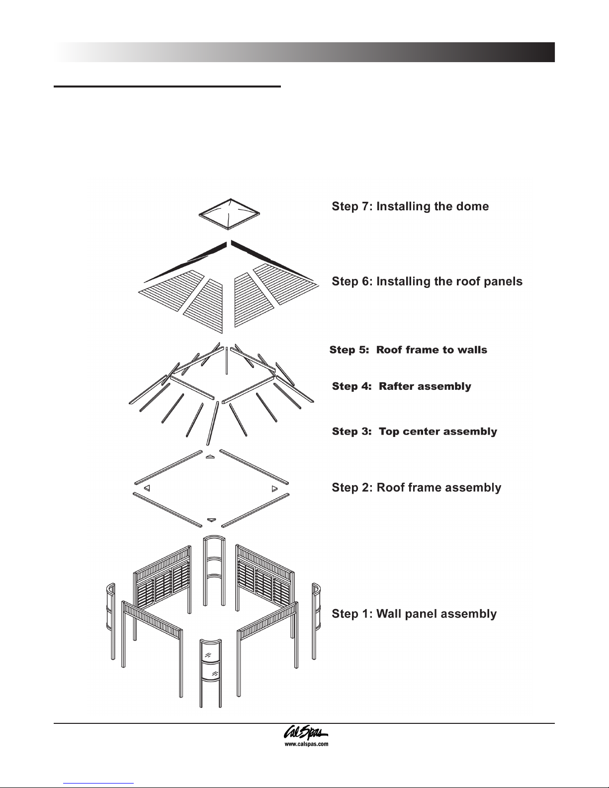
Order of Assembly
Whether you assemble your gazebo yourself or hire someone to do it, your new Bayside gazebo needs to be
assembled in a specic order. Our Cal Enclosures professionals have determined through their experience that this
is the easiest way to assemble your gazebo.
2008 Gazebo Owner’s Manual Page 3
LTR20081011, Rev. A
Page 6
Bayside Gazebo Assembly
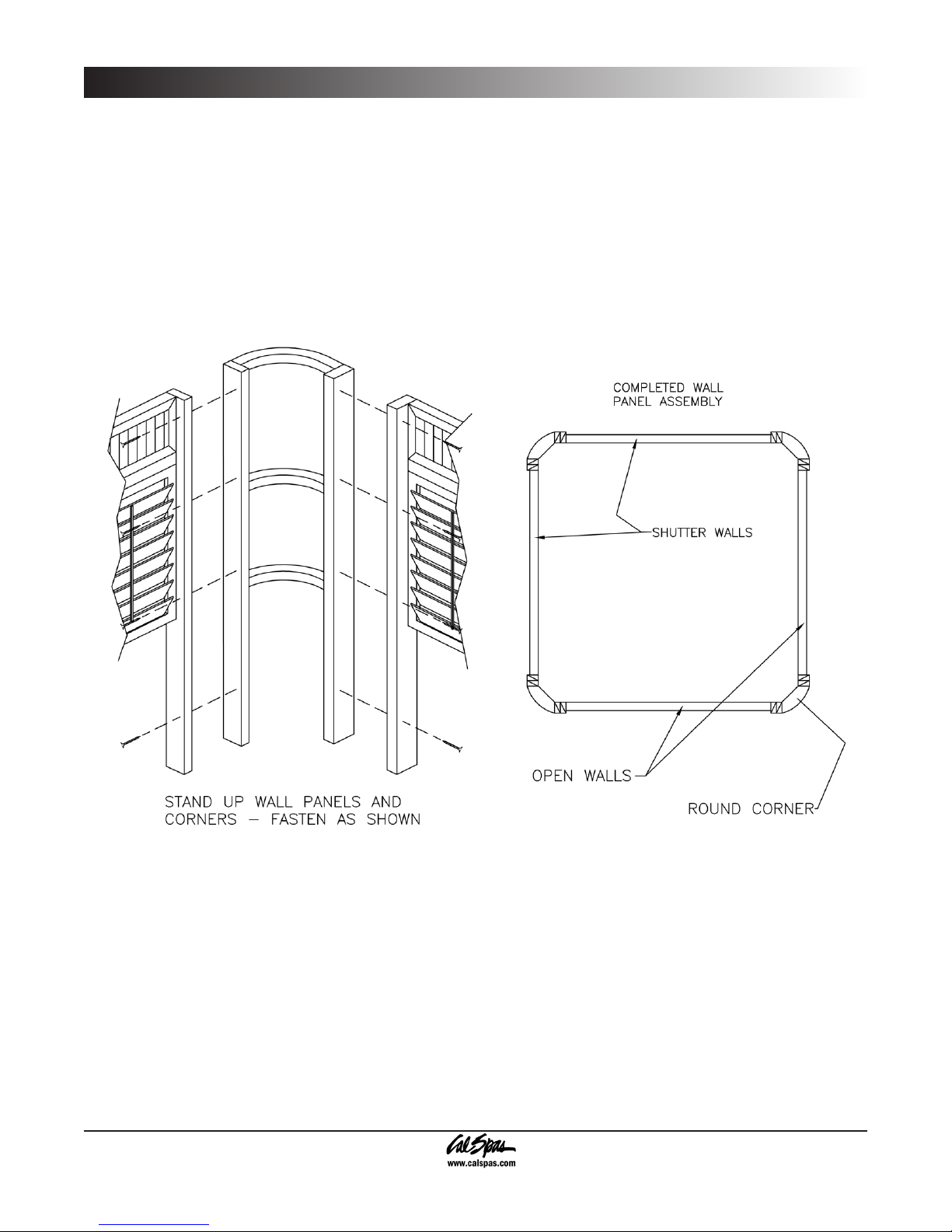
Step 1: Wall Panel Assembly
Follow the written steps in conjunction with the gures that are shown.
Stand a wall panel and a corner up side by side. Attach the panels together using 4 drywall screws .
1.
Repeat this step until all the panels are attached. The gure below shows the proper arrangement of panels.
2.
The owner must use care when securing the wall panels and rounded corners together, as any damage incurred
during assembly is not covered by the warranty.
Be sure that the screws do not come in contact with the windows.
Page 4 2008 Gazebo Owner’s Manual
LTR20081011, Rev. A
Page 7
Bayside Gazebo Assembly
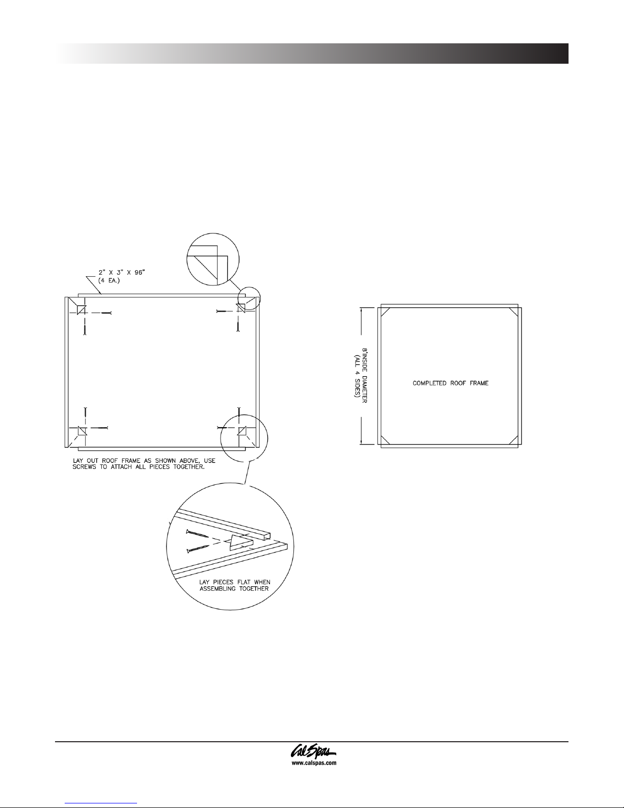
Step 2: Roof Frame Assembly
When assembling the roof frame, it is recommended that you lay everything out and assemble it on a at surface.
These directions are generalized, relating to measurements.
Check the parts list that came with your gazebo and make sure that all the parts are present. Also, please follow the
written steps in conjunction with the gures that are shown.
Take four 2”x3”x96” pieces of wood and lay them out on the ground, in effect making a square.
1.
Place corner stabilizers (4 each) and attach in each corner using drywall screws.
2.
Use the provided drywall screws to attach all the pieces together. The completed roof frame should measure 8’
3.
across (inside dimensions) on all sides).
2008 Gazebo Owner’s Manual Page 5
LTR20081011, Rev. A
Page 8

Bayside Gazebo Assembly
Step 3: Top Center Assembly
1. Attach each corner together with the provided screws, making sure to keep the 45 degree corners pointing
outward. This is the top center frame.
2. Take the hip rafters (4 each) and attach them to each corner of the top center frame. Make sure that the 45
degree corner matches the 45 degree end on the hip rafters.
Page 6 2008 Gazebo Owner’s Manual
LTR20081011, Rev. A
Page 9

Step 4: Rafter Assembly
Attach the hip rafter assembly to the top center
1.
frame (Figure A).
Attach 4 common rafters to the middle of each
2.
side of the top center frame assembly. Use the
toe-in method (see inset).
With the common rafters now installed, attach
3.
the the remaining rafters. Make sure that each
rafter is spaced evenly apart. This will ensure
sufcient anchoring points for the roof panels
(Figure B).
NOTE: It is recommended that you have an
assistant for the following step.
Bayside Gazebo Assembly
2008 Gazebo Owner’s Manual Page 7
LTR20081011, Rev. A
Page 10
Bayside Gazebo Assembly
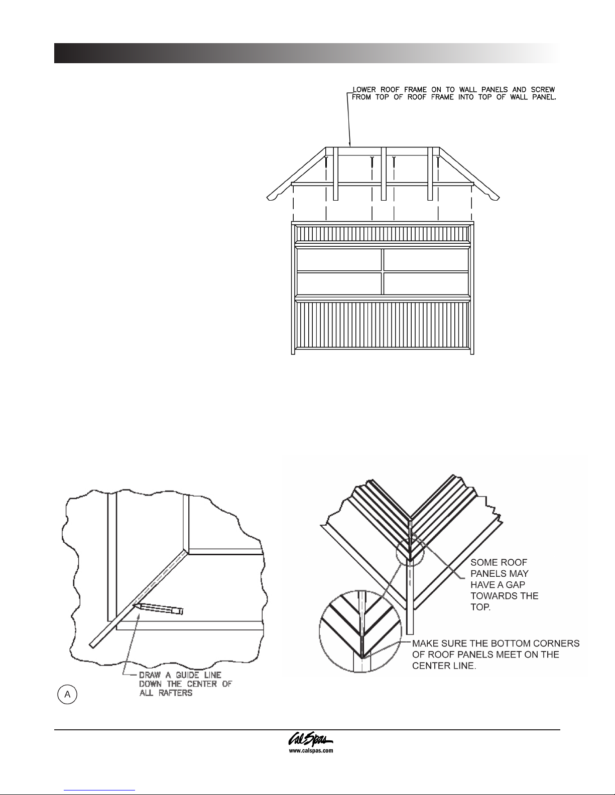
Step 5: Roof Frame to Walls
Place the assembled roof and rafter assembly
on top of the wall panel assembly. Anchor the
roof section by using drywall screws.
Step 6: Installing the Roof Panels
It is strongly recommended that you use a ladder for the nal steps of the gazebo assembly.
Prior to installing the roof panels, a center line must be drawn on the top side of each rafter. 1.
Page 8 2008 Gazebo Owner’s Manual
LTR20081011, Rev. A
Page 11
Place each roof panel in place. Be sure
2.
the bottom corners are aligned on the
center line. Faster using the provided
screws (Figure 9).
When roof panels meet at corners,
sometimes a gap will be present. Be sure
that the bottom corners meet at the center
line.
Bayside Gazebo Assembly
Use the provided screws to mount
3.
all ridge caps (Figure 10).
2008 Gazebo Owner’s Manual Page 9
LTR20081011, Rev. A
Page 12
Bayside Gazebo Assembly
Step 7: Installing the
Dome
The nal steps of the gazebo assembly
will require the use of a ladder.
Install the provided metal brackets
1.
on the center of each dome side
(Figure A).
Lower the dome assembly on to the
2.
top roof frame (Figure B).
From the inside the gazebo secure
3.
the dome assembly to the roof
assembly using the dome brackets
and drywall screws. There will be
four dome brackets that will connect
to each side of the dome frame.
Page 10 2008 Gazebo Owner’s Manual
LTR20081011, Rev. A
Page 13
Spa Cabana Gazebo Assembly
5
5
4
4
3
3
6
12
2
2
2
2
2
1
1
1
1
9
8
10
Spa Cabana Gazebo Assembly
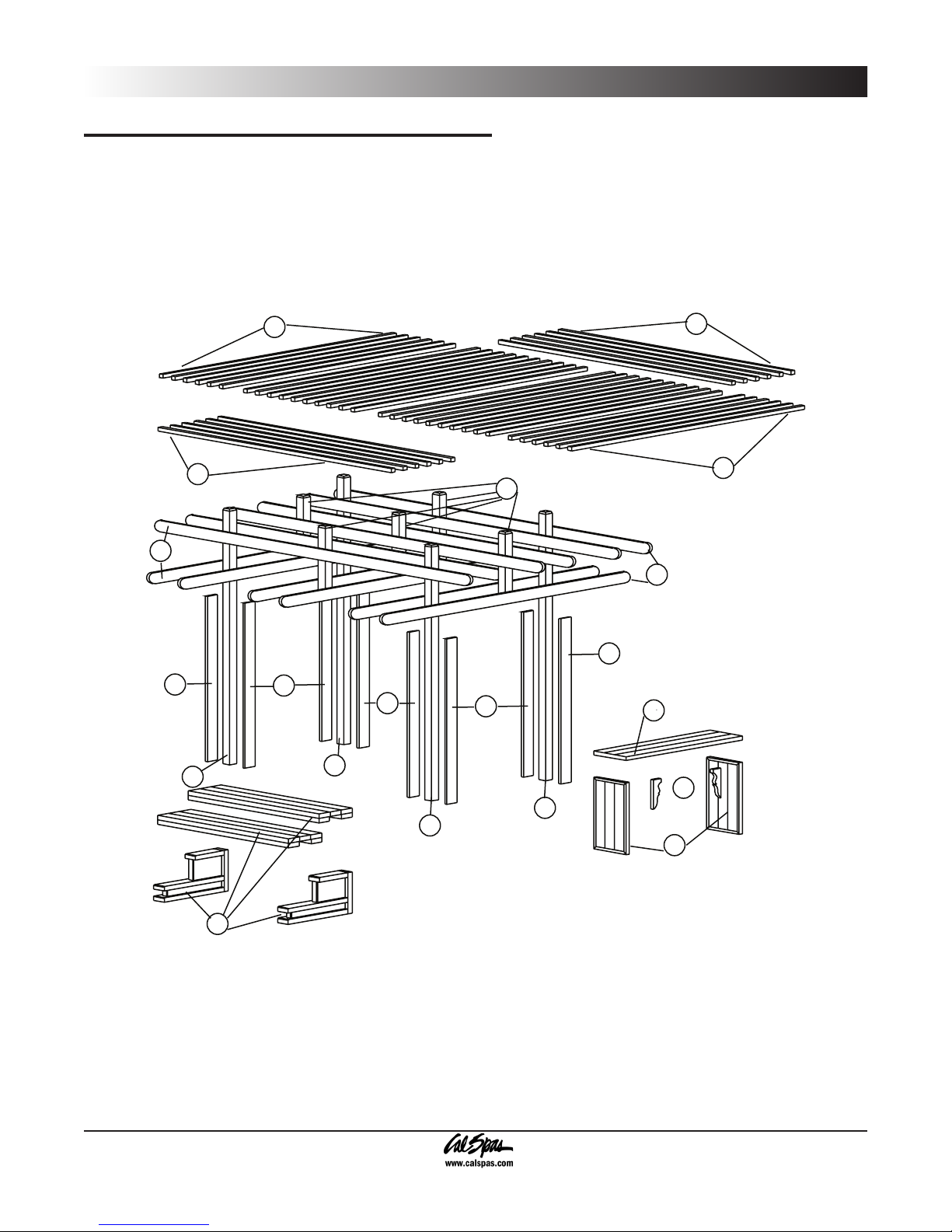
Exploded View of Assembly
Whether you assemble your gazebo yourself or hire someone to do it, your new gazebo needs to be assembled in
a specic order. Our Cal Enclosures professionals have determined through their experience that this is the easiest
way to assemble your gazebo.
2008 Gazebo Owner’s Manual Page 11
LTR20081011, Rev. A
Page 14
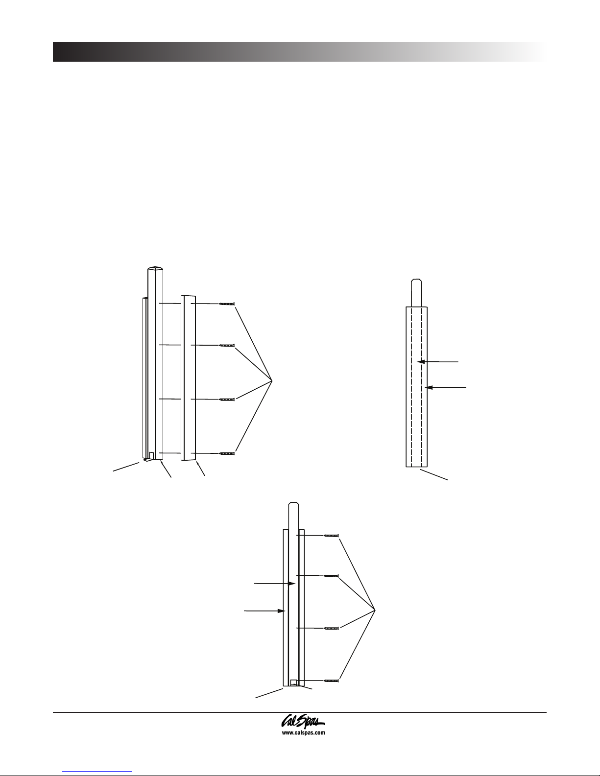
Spa Cabana Gazebo Assembly
4" x 4" & 2" x 6" should
be flush at the bottom.
Galvanized "L" Bracket
3"x8"
Drywall Screw
Side View Of Main
Support Post
4" x 4" & 2" x 6" should
be flush at the bottom.
4" x 4"
2" x 6"
3"x8"
Drywall Screw
Front View Of Main
Support Post
Galvanized "L" Bracket
2" x 6"
4" x 4"
4" x 4" & 2" x 6" should
be flush at the bottom.
Step 1: Corner Post Assembly
Using the materials that are provided in your gazebo kit, take one 4”x4”x108’ (9’) piece of lumber and 2 2”x6”x90”
1.
(7 1/2’) pieces of lumber.
Take the 2”x6” and center the lumber on the 4”x4”piece of lumber. Once this is done, take four 2 1/2” screws
2.
(3”x8”) and attach the 2”x6” to the 4”x4”. Repeat this sequence for the other 2”x6”.
The 4”x4” and the 2”x6” (both pieces) should be ush at the bottom.
Once this is complete, repeat these steps for all four sides of the gazebo.
3.
Using the provided hardware, attach the galvanized “L” bracket to the 4”x4” (either side).
4.
With the use of a level, and after ensuring that the 2”x6” is between the spa and the 4”x4”, check that the support
5.
is level (top to bottom), and mark the location of the anchoring hole by scoring the concrete.
Page 12 2008 Gazebo Owner’s Manual
LTR20081011, Rev. A
Page 15
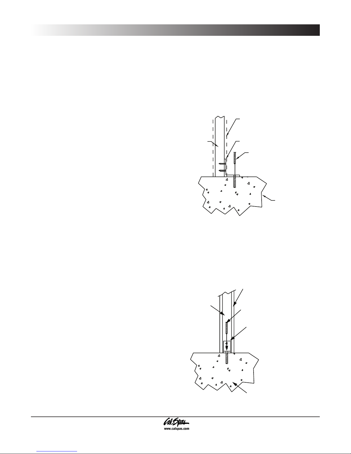
Step 2: Anchoring the Main
Anchor post into concrete as shown.
Concrete Foundation
Anchoring Bolt
Galvanized "L" Bracket
4"x 4" Post
Determine spacing of post with spa size
before anchoring into concrete.
2" x 6" Board
Anchoring Bolt
Galvanized "L" Bracket
2" x 6" Board
4"x 4" Post
Side View
Front View
Concrete Foundation
Determine spacing of post with spa size
before anchoring into concrete.
Support Post
When scoring the concrete, make sure that the mark
is dark enough to see, as you will be drilling a hole in
the concrete. This hole will be where the anchoring
bolt is located. Also, it is the owner’s responsibility to
obtain a 1/2” masonry bit. This bit will be used to drill the
anchoring holes in the foundation. A masonry bit may be
bought at any local hardware store.
Spa Cabana Gazebo Assembly
Refer to the gure for steps 1 through 3.
Pre-drill the anchoring hole using a 1/2” masonry
1.
drill bit. Drill the hole to a depth of no less than 3”.
Using a hammer, insert the anchoring bolt by gently
tapping the bolt into place. Continue to tap into
place until the anchoring bolt is seated securely in
the hole.
After drilling the hole and inserting the anchoring
2.
bolt, slide the main support post assembly on to the
anchoring bolt and tighten down using the provided
hardware.
Repeat these steps for all four corners of the
3.
gazebo.
2008 Gazebo Owner’s Manual Page 13
LTR20081011, Rev. A
Page 16
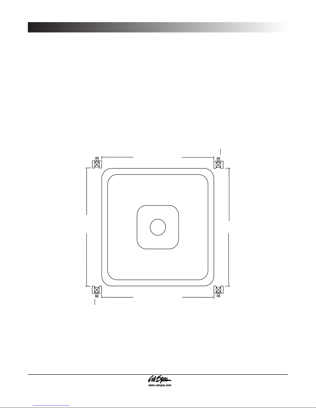
Spa Cabana Gazebo Assembly
Galvanized "L" Bracket
Galvanized "L" Bracket
8' - 2"
(7' - 2" , 7' - 8")
8' - 2"
(7' - 2" , 7' - 8")
8' - 2"
(7' - 2" , 7' - 8")
8' - 2"
(7' - 2" , 7' - 8")
The nal placement of the main support posts is shown at right. The main support posts should be mounted no less
than 1” from the side of the spa. If the gazebo is touching the spa, and any damage is incurred due to contact, the
warranty on the spa siding is void.
The total distance between each main support post will be determined by the size of the spa and gazebo that was
purchased. The Cabana Gazebo has 3 sizes: 7’x7’, 7.5’x7.5’, and 8’x8’. The desired distance between each main
support post will be determined by the aforementioned sizes.
The list below will tell you what each distance should be for each gazebo model :
If the spa is: Then the distance between each gazebo main support post is....
7’ x 7’ +/- 7’ - 2” x 7’ - 2”
7.5’ x 7.5’ +/- 7’ - 8” x 7’ - 8”
8’ x 8’ +/- 8’ - 2” x 8’ - 2”
Page 14 2008 Gazebo Owner’s Manual
LTR20081011, Rev. A
Page 17

Step 3: Roof Assembly
The roof assembly is a relatively easy process. The majority of
the tasks are repetitive. The rst part of the roof that needs to be
assembled are the support members. Install the lower support
members rst and the upper support members second. The
support members are the 2”x6”x144” (12’).
Support Member Assembly
This step requires the help of another person. Use two ladders
when hanging the main support beams.
Tip: Try anchoring the ladders so they don’t move while you’re on
top of them.
With the aid of a ladder, place one 2”x6”x144” roof support
1.
on top of the 2”x6”x90” piece and anchor it to the 4”x4”, using
the provided 2 1/2” screws. Make sure that the 2”x6”x144”
is centered between the two 4”x4” main
support posts.
Place another 2”x6”x144” roof support on
2.
the opposite side of the 4”x4” main support
post. Screw this piece to the 4”x4” as well.
Spa Cabana Gazebo Assembly
Repeat this process on the other main
3.
support posts that are directly across
from the main support posts that were just
completed.
Referring to Figure A, place another
4.
2”x6”x144” roof support on top of the roof
support that was just installed. This next
roof support will in effect create a 90 degree
angle with the other 2”x6”x144” roof support.
Secure the roof support with the provided 2
1/2” screws (Figures B and C).
Repeat these steps for the remaining roof
5.
support beams (Figure D).
The 4”x4”x16” post is used to tie the roof grid together
and re-enforce it (shown at right). These posts should
be mounted ush with the bottom of the roof support
beams so they are at the same height as the main
support posts.
2008 Gazebo Owner’s Manual Page 15
LTR20081011, Rev. A
Page 18

Spa Cabana Gazebo Assembly
2" x 2" x 144"
spaced 2 1/2" apart
2" x 2" x 140"
spaced 2 1/2" apart
2" x 2" x 144" Roof Slats
2" x 2" x 140"
NOTE: Please observe the two different directions
that the roof slats are going.
Upper Level Roof Slats
Lower Level Roof Slats
Roof Final Assembly
Lay out the 2”x2”x140” roof slats on
1.
the two lower levels of the gazebo.
Make sure that each roof slat is
spaced exactly 2 1/2” apart. Twelve
roof slats total will be used on the
lower level.
Secure each roof slat securely in
2.
place with 2 1/2” screws.
Lay out the 2”x2”x144” roof slats on
3.
the one upper level of the gazebo.
Make sure that each roof slat is
spaced exactly 2 1/2” apart. These
roof slats need to be running the
opposite direction as the lower level
roof slats.
Page 16 2008 Gazebo Owner’s Manual
LTR20081011, Rev. A
Page 19

901 Spa Cabana Gazebo Assembly
901 Spa Cabana Gazebo Assembly
The following will tell you how to assemble your 901 Spa Cabana gazebo. If you have any questions, problems with
material and/or parts, contact your local retailer.
Step 1: Assembling the Gazebo
Corner and side panel assembly
Stand up corner posts and attach a side panel as shown.
Repeat this step for the other side panel until all of the
corner posts are standing.
Rear cross beams
Place and attach the rear cross beams as shown.
Front cross beams
Place and attach the front cross beams as shown.
Rear diagonal beams
Place and attach the rear diagonal beams as shown.
2008 Gazebo Owner’s Manual Page 17
LTR20081011, Rev. A
Page 20

901 Spa Cabana Gazebo Assembly
Front section assembly
Assemble the front section by placing the front
diagonal beams 11” in from the out edge of the front
beam as shown.
Front section attachment
Attach the front section to the structure as shown.
Top cross beam assembly
Place top cross beams with an equal overhang
on each end as shown.
Page 18 2008 Gazebo Owner’s Manual
LTR20081011, Rev. A
Decorative posts and fastening
Place and attach decorative posts as shown. Fasten top
cross beams as shown.
Page 21

Canopy assembly
Anchor post into concrete as shown.
Concrete Foundation
Anchoring Bolt
Galvanized "L" Bracket
4"x 4" Post
Determine spacing of post with spa size
before anchoring into concrete.
2" x 6" Board
Anchoring Bolt
Galvanized "L" Bracket
2" x 6" Board
4"x 4" Post
Side View
Front View
A
B
Concrete Foundation
Place and attach canopy pieces as shown. Start with the longest center
pieces and work outward. Pieces should be separated by 2 1/2” and
overhang on each end by 5”.
901 Spa Cabana Gazebo Assembly
Step 2:
Anchoring the Main Support
Post
When scoring the concrete, make sure that the mark
is dark enough to see, as you will be drilling a hole in
the concrete. This hole will be where the anchoring
bolt is located. Also, it is the owner’s responsibility to
obtain a 1/2” masonry bit. This bit will be used to drill the
anchoring holes in the foundation. A masonry bit may be
bought at any local hardware store.
Pre-drill the anchoring hole using a 1/2” masonry
1.
drill bit. Drill the hole to a depth of no less than 3”.
Using a hammer, insert the anchoring bolt by gently
tapping the bolt into place. Continue to tap into place
until the anchoring bolt is seated securely in the
hole.
After drilling the hole and inserting the anchoring
2.
bolt, slide the main support post assembly on to the
anchoring bolt and tighten down using the provided
hardware.
Repeat these steps for all three corners of the
3.
gazebo.
2008 Gazebo Owner’s Manual Page 19
LTR20081011, Rev. A
Page 22

901 Spa Cabana Gazebo Assembly
Bar with corbels
Corbel fits into corner
Bottom View
INSTRUCTIONS
1. Place bar top face down.
2. Place bar legs w/detail facing outwards and fasten to bar top
with 2 1/2" screws.
3. Fasten bar corbel to bar top and bar legs with 2 1/2" screws.
1
2
3
2
Bar and Corbel, Step, and Stool Assembly
The following will tell you how to assemble your
bar and corbel, bar stool, and steps. If you have
any questions, problems with material and/or parts,
contact your local retailer.
Bar and Corbel
Place the bar top face down on the ground.
1.
Use care when placing the bar top on the ground. It
is recommended that a sheet, or a blanket, be placed
on the ground with the bar top being placed on top of
the material.
Place the bar legs with the decorative nish
2.
facing outward. Fasten to the bar top with 2 1/2”
screws.
Fasten bar corbel to bar top and bar legs with 2
3.
1/2” screws.
Once the bar assembly is complete, place the bar
between the main support posts. Push the bar
assembly all the way against the spa. Attach the bar
to the main support posts by using 2 1/2” screws.
LTR20081011, Rev. A
Page 20 2008 Gazebo Owner’s Manual
Page 23

Step
Use Toe-In Method As
Shown, On Both Sides
Step
Legs
A
B
Stand the legs up at 5’ apart. Place the upper
1.
step on top of the upper section of the step.
To attach the step, screw in 4 screws (2 at
2.
each rear corner): 1 into the step leg and 1
into the step itself.
Place the lower step on the lower section of
3.
the step.
To attach the step, screw in 4 screws (2 on
4.
each on the outside of the step. Use the toe-in
method on both sides, as shown.
901 Spa Cabana Gazebo Assembly
2008 Gazebo Owner’s Manual Page 21
LTR20081011, Rev. A
Page 24

901 Spa Cabana Gazebo Assembly
1. Attach sides to legs.
2. Attach seat to leg assembly.
Bar stool legs
Bar stool
support brace
Bar stool
seat
A
B
C
Bar Stool
The nal step in the assembly of your Cabana Gazebo is the
assembly of your bar stools).
Attach the bar stool legs to the support brace using the
1.
provided 2 1/2” screws. There will be a total of 12 screws.
Place the bar stool seat on a at surface (make sure that
2.
the nish side is on the ground). Attach the leg assembly
using four 2 1/2” screws.
Page 22 2008 Gazebo Owner’s Manual
LTR20081011, Rev. A
Page 25

Lattice Gazebo Assembly
2
1
5
1
5
5
5
5
5
5
6
3
4
4
4
4
4
4
4
7
3
4
11
11
7
7
16
5
5
5
5
1
1
2
Lattice Gazebo Assembly
Order of Assembly
Whether you assemble your gazebo yourself or hire someone to do it, your new gazebo needs to be assembled in
a specic order. Our Cal Enclosures professionals have determined through their experience that this is the easiest
way to assemble your gazebo.
2008 Gazebo Owner’s Manual Page 23
LTR20081011, Rev. A
Page 26

4' or 5' Panel
4' or 5' Panel 4', 5' or 8' opening
2"x2" Post Application
4"x4" Post Application
Chamfered End
4' Panel
4' Panel
4' Panel
4' Panel
4' Panel
4' Panel
4' Panel
4' Panel
4' Panel
4' Panel
8' Panel
8' Panel
A
B
Lattice Gazebo Assembly
Step 1: Wall Panel Assembly
All wall panels are pre-assembled at the factory before being shipped. Check the parts list that came with your
gazebo and make sure that all the parts are present.
Stand two panels up side by side. Attach the panels together using ve 2 1/2” screws (Figure A). Make sure the
1.
smooth side of each wall panel is facing the inside of the gazebo.
Each corner should be secured following the sample in Figure B (inset).
2.
Repeat this step until all the panels are
3.
attached. Figure B will show you the
wall panel layout.
The rounded corners attach to the wall
panels the same way, with ve 2 1/2”
screws. The owner must use care when
securing the wall panel and rounded corner
together, as any damage incurred during
assembly is not covered by the warranty.
Use care when attaching the sides and
corners. Be sure that the screws do not
come in contact with the windows.
Page 24 2008 Gazebo Owner’s Manual
LTR20081011, Rev. A
Page 27

Step 2: Roof Frame Assembly
COMPLETED ROOF FRAME
16' Inside Diameter
12' Inside Diameter
2"x3"x96"
(4 each)
2"x2"x24"
(4 each)
2"x3"x72"
(4 each)
Lay out roof frame as shown above. Use
screws to attach all pieces together.
A
B
Side View
2"x4"x93
Single Slider
(4 each)
2"x4"x93
Double Slider
(2 each)
2"x4"x72"
(4 each)
Top Center Frame
8' x 12' Outside Diameter
24 3/4"
47 1/4"
24 3/4"
47 1/4"
C
When assembling the roof frame, lay everything out and
assemble it on a at surface. Have an assistant help you
when installing the roof frame on to the gazebo walls.
Take four 2”x4”x96” pieces of wood and four
1.
2”x4”x72” pieces of wood and lay them out on the
ground (Figure A), in effect making a square.
Use the provided 2 1/2” screws to attach all the
2.
pieces together. When complete, the outside
diameter should measure 12’x16’ (Figure B).
Place corner stabilizer (4 each) and attach in each
3.
corner (Figure A) using 2 1/2” screws. Take four
2”x2”x24” pieces of wood and attach to each center
point on the side of the roof frame.
Attach each corner together with the provided
4.
screws, making sure to keep the 45 degree corner
pointing outward (Figure C - inset). This is the top
center frame.
Take four single-slider rafters and two double-slider
5.
rafters attach them to the middle of each side of
the top center frame assembly (Figure C). Use the
toe-in method (see inset) and follow the specied
measurements (Figure C).
Lattice Gazebo Assembly
2008 Gazebo Owner’s Manual Page 25
LTR20081011, Rev. A
Page 28

Lattice Gazebo Assembly
Lower roof frame onto wall
panels and screw from top
of roof frame into top of wall.
F
Hip Rafter
Top Center of Frame
Slider board should be placed flush
with bottom of top center of frame.
Attach 4 each hip rafters flush w/top with 3" screws.
D
Common Rafter
Hip Rafter
Toe in hip rafter with screws
into the roof frame.
48"
48"
24"
(On Center)
E
Take the hip rafters (4 each) and attach them to each
6.
corner of the top center frame. Make sure that the 45
degree corner matches the 45 degree end on the hip
rafters (Figure D).
Take 4 common rafters and attach them to the middle
7.
of each side of the top center frame assembly (Figure
D). Use the toe-in method (see inset).
With the common rafters now installed, attach the
8.
remaining jack rafters using the toe-in method. Make
sure that each jack rafter is spaced evenly apart. This
will ensure sufcient anchoring points for the roof
panels.
Figure E shows what the roof frame will look like when
9.
it is completed.
It is recommended that you have an assistant for the
following step.
Place the assembled roof section on top of the wall
10.
panel assembly. Anchor the roof section by using 2
1/2” screws (Figure F).
Page 26 2008 Gazebo Owner’s Manual
LTR20081011, Rev. A
Page 29

Lattice Gazebo Assembly
A
B
Panel
Support
Panel
Support
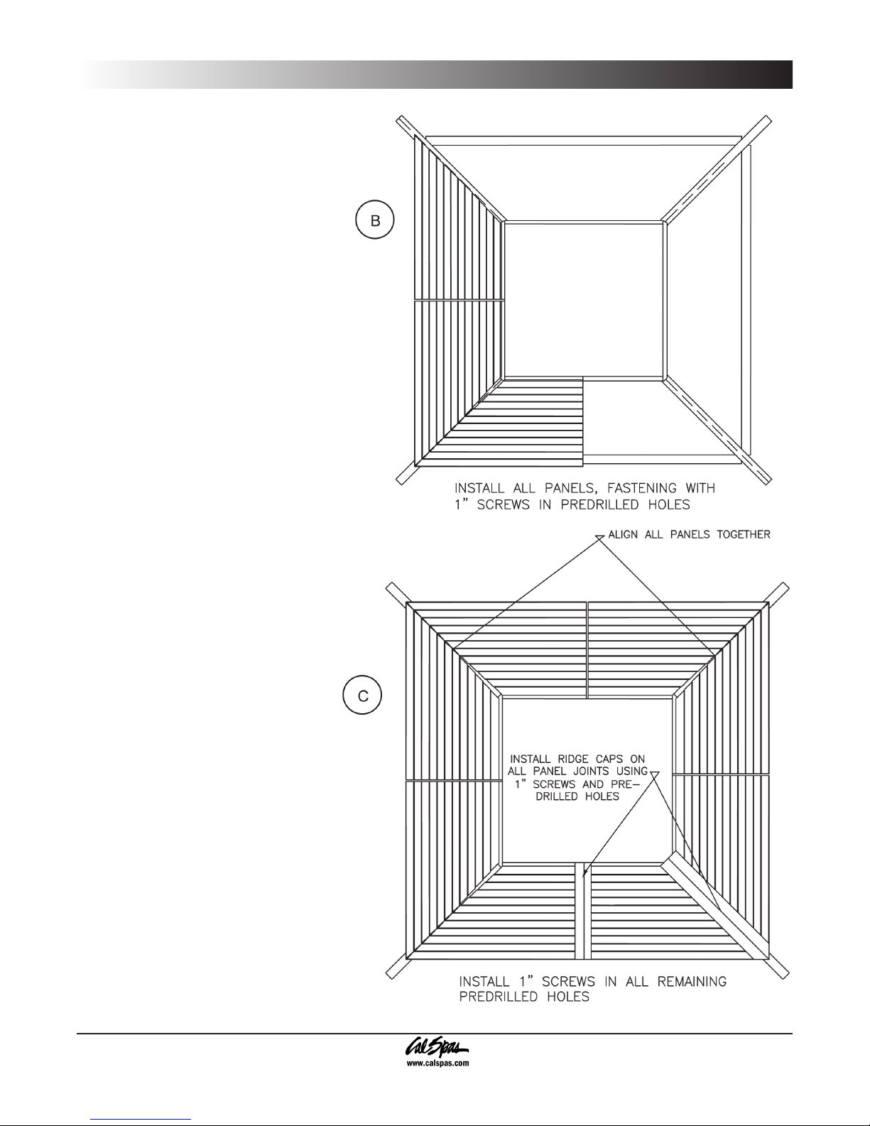
Step 3: Roof Panel Installation
It is strongly recommended that you use
a ladder for the nal steps of the gazebo
assembly.
Place each roof panel in place (with the
1.
edge resting on the panel supports) and
mount using 2 1/2” screws (Figure A).
If your model gazebo has a dome roof, refer
to Step 3.
Using the provided hardware, mount the
2.
dome bracket (Figure B).
Use 2 1/2” screws to mount all ridge
3.
caps.
Set the roof assembly onto the wall
4.
panel assembly and attach using 2 1/2”
screws.
2008 Gazebo Owner’s Manual Page 27
LTR20081011, Rev. A
Page 30

Luxury Gazebo Assembly
Luxury Gazebo Assembly
Order of Assembly
Whether you assemble your gazebo yourself or hire someone to do it, your new gazebo needs to be assembled in
a specic order. Our Cal Enclosures professionals have determined through their experience that this is the easiest
way to assemble your gazebo.
Page 28 2008 Gazebo Owner’s Manual
LTR20081011, Rev. A
Page 31

Luxury Gazebo Assembly
Step 1: Wall Panel Assembly
Follow the written steps in conjunction with the gures that are shown.
Stand two panels up side by side. Attach the panels together using ve 2 1/2” screws (Figure A).
1.
Repeat this step until all the panels are attached (Figure B).
2.
The rounded corners attach to the wall panels the same way, with ve 2 1/2” screws. The owner must use care when
securing the wall panel and rounded corner together, as any damage incurred during assembly is not covered by
the warranty.
Caution: Use care when attaching the sides and corners. Be sure that the screws do not come in contact with the
windows.
2008 Gazebo Owner’s Manual Page 29
LTR20081011, Rev. A
Page 32

10' Inside Diameter
Completed Roof Frame
2"x3"x98 1/2"
(4 each)
2"x2"x24
(4 each)
2"x3"x60"
(4 each)
Lay out roof frame as shown above. Use
screws to attach all pieces together
16" Inside Diameter
B
A
10' Inside Diameter
Completed Roof Frame
2"x3"x98 1/2"
(4 each)
2"x2"x24
(4 each)
2"x3"x60"
(4 each)
Lay out roof frame as shown above. Use
screws to attach all pieces together
16" Inside Diameter
2"x4"x22 1/2"
(2 each)
2"x4"x94 1/2"
(2 each)
Top Center Frame
2'x8' Outside Diameter
C
B
A
10' Inside Diameter
Completed Roof Frame
(4 each)
2"x2"x24
(4 each)
2"x3"x60"
(4 each)
Lay out roof frame as shown above. Use
screws to attach all pieces together
16" Inside Diameter
2"x4"x22 1/2"
(2 each)
2"x4"x94 1/2"
(2 each)
Top Center Frame
2'x8' Outside Diameter
Hip Rafter
Top Center Frame
Attach 4 each Hip rafters flush w/Top
D
C
B
Luxury Gazebo Assembly
Step 2: Roof Frame Assembly
When assembling the roof frame, it is recommended that
you lay everything out and assemble it on a at surface.
The owner should also note that there are different
sizes in the Luxury line of gazebos. These directions are
generalized, relating to measurements.
Check the parts list that came with your gazebo and
make sure that all the parts are present. Also, follow
the written steps in conjunction with the gures that are
shown.
Take four 2”x4”x98 1/2” pieces of wood and lay
1.
them out on the ground (Figure A), in effect making
a square.
Place corner stabilizers (4 each) and attach in each
2.
corner using 2 1/2” screws. Attach 2”x2”x24” splice
(4 each) at each center joint. This will reinforce the
roof frame (Figure A).
Use the provided 2 1/2” screws to attach all the
3.
pieces together (Figure B).
Attach each corner together with the provided
4.
screws, making sure to keep the 45 degree corners
pointing outward (Figure C - inset). This is the top
center frame.
Take the hip rafters (4 each) and attach them to
5.
each corner of the top center frame. Make sure that
the 45 degree corner matches the 45 degree end on
the hip rafters (Figure D).
Page 30 2008 Gazebo Owner’s Manual
LTR20081011, Rev. A
Page 33

Jack Rafter
48" 24"
On Center
Jack Rafter
Hip Rafter
Hip Rafter
Common Rafter
Toe-in hip rafter with screws
into roof frame
E
Jack Rafter
48" 24"
On Center
Jack Rafter
Hip Rafter
Hip Rafter
Common Rafter
Toe-in hip rafter with screws
into roof frame
E
F
Lower roof frame on to wall
panels and screw from top of
roof frame into top of wall panel.
Jack Rafter
48" 24"
On Center
Jack Rafter
Hip Rafter
Hip Rafter
Common Rafter
Toe-in hip rafter with screws
into roof frame
E
G
F
Luxury Gazebo Assembly
Attach the rafter assembly to the roof frame
6.
using the toe-in method (Figure E)
Take 4 common rafters and attach them to
7.
the middle of each side of the top center
frame assembly. Use the toe-in method
(Figure E - inset).
With the common rafters now installed,
8.
attach the remaining jack rafters using
the toe-in method. Make sure that each
jack rafter is spaced evenly apart. This will
ensure sufcient anchoring points for the
roof panels.
look like when it is completed.
Figure F shows what the roof frame will
9.
You will need someone to assist you with the
following step.
Place the assembled roof section on top
10.
of the wall panel assembly. Anchor the
roof section by using 2 1/2” screws.
2008 Gazebo Owner’s Manual Page 31
LTR20081011, Rev. A
Page 34

A
Some roof panels may
have a gap at the top
of the panels
A
B
Some roof panels may
have a gap at the top
of the panels
Use 1 1/2" screw
Use
1" screw
IMPORTANT
Center all roof panels
on rafters
Install ridgecaps
after all panels
are installed on
center of rafters
A
B
C
Ridgecap
Luxury Gazebo Assembly
Step 3: Roof Panel Installation
It is strongly recommended that you use a ladder for the
nal steps of the gazebo assembly.
Prior to installing the roof panels, a center line must
1.
be drawn on the top side of each rafter (Figure A).
Place each roof panel in place (with the edge being
2.
ush with the center line) and mount using 2 1/2”
screws (Figure B).
Using the provided hardware, mount the dome
3.
bracket (Figure C).
Use the provided 1 1/2” screws to mount all ridge
4.
caps (Figure C).
Page 32 2008 Gazebo Owner’s Manual
LTR20081011, Rev. A
Page 35

Steel roof panels interlock together
as shown in magnified view
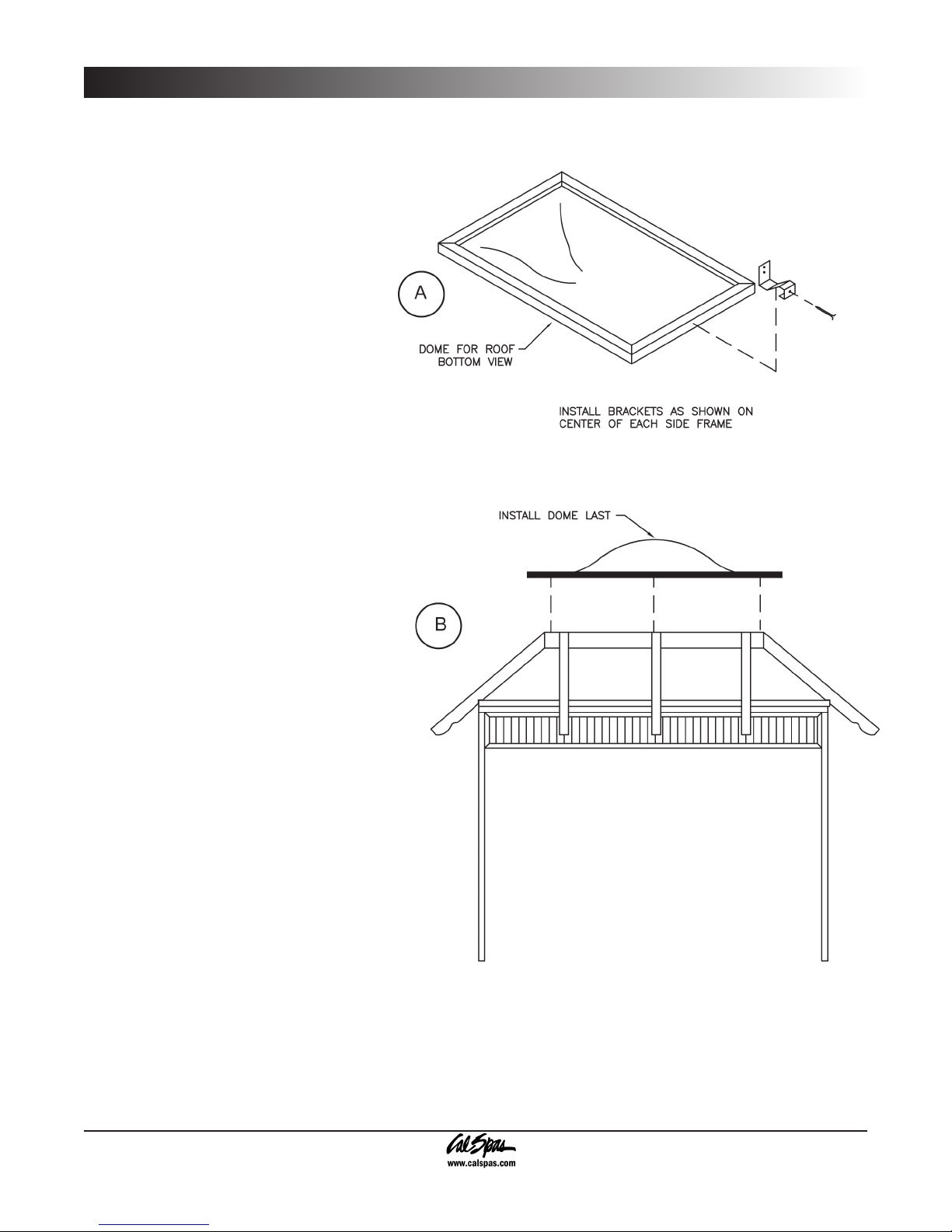
Install dome
last
Dome for roof
bottom review
Install brackets as shown
on center of each side of
dome frame
A
B
Step 4: Dome Installation
The nal steps of the gazebo assembly will require the
use of a ladder.
Attach the four dome brackets to the center of each
1.
side of the dome frame (Figure A).
Lower the dome assembly onto the top center
2.
frame.
From the inside the gazebo secure the dome
3.
assembly to the roof assembly using the dome
brackets and 2 1/2” screws. There will be four dome
brackets that will connect to each side of the dome
frame.
Luxury Gazebo Assembly
2008 Gazebo Owner’s Manual Page 33
LTR20081011, Rev. A
Page 36

Northeast Gazebo Assembly
Northeast Gazebo Assembly
Order of Assembly
Whether you assemble your gazebo yourself or hire someone to do it, your new Northeast gazebo needs to be
assembled in a specic order. Our Cal Enclosures professionals have determined through their experience that this
is the easiest way to assemble your gazebo.
Page 34 2008 Gazebo Owner’s Manual
LTR20081011, Rev. A
Page 37

Northeast Gazebo Assembly
Step 1: Wall Panel Assembly
All wall panels are pre-assembled at the factory before being shipped. The smooth side of each wall panel should
be facing the inside of the gazebo.
Follow the written steps in conjunction with the gures that are shown.
Place the wall panel on a at surface. Be sure not to set it on any surface that can possibly scratch the surface
1.
of the windows.
Fit the rounded luxury corner onto the wall panel and attach using the provided 2 1/2” screws (Figure A). Repeat
2.
this step for the remaining wall panels.
Referring to Figure B, make sure that each wall panel (2 each) is securely attached to each rounded luxury
3.
corner (3 each).
2008 Gazebo Owner’s Manual Page 35
LTR20081011, Rev. A
Page 38

Northeast Gazebo Assembly
Step 2: Roof Frame Assembly
It is suggested that the owner have a helper for the next
steps, as heavy objects must be lifted.
Take 3 2”x4”x46 1/2” pieces and attach them
1.
together, making a triangle, and ensuring that the
45DE angle-cut is facing out (Figure A). This is the
top center frame.
Take three hip rafters and attach them to the 45DE
2.
angle at each corner of the top center frame. Secure
using 2 1/2” screws (Figure A).
Place the assembled roof frame onto the assembled
3.
wall panels (Figure A) and attach using the provided
2 1/2” screws.
Attach two roof panels (47”x109”) and secure using
4.
2 1/2” screws. Center each panel on the hip rafters
(Figure C).
Place moon roof (48”x48”x65 1/2”) on top of roof
5.
assembly and secure using 2 1/2” screws (Figure
C).
Attach the crown molding and roof ridgecaps with 2
6.
1/2” screws (Figure B and C).
Page 36 2008 Gazebo Owner’s Manual
LTR20081011, Rev. A
Page 39

Step 3: Step and Bar
Assembly
Stand the legs up at 5’ apart. Place the upper
1.
step on top of the upper section of the step
(Figure A).
To attach the step, screw in 4 screws (2 at
2.
each rear corner): 1 into the step leg and 1
into the step itself (see insert of Figure A).
Place the lower step on the lower section of
3.
the step (Figure B).
To attach the step,screw in 4 screws (2 on
4.
each on the outside of the step - see insert
in Figure B). Use the toe-in method on both
sides, as shown.
The manufacturer recommends mounting corbels
on the cabinet so that the bar top sits just under
the spa lip.
Using 2 1/2” screws, mount the corbels directly
5.
to the cabinet wall (Figure C). Make sure that
the corbels are horizontally level with each
other.
Northeast Gazebo Assembly
Mount the bar top to the corbels with the 2
6.
1/2” screws (Figure C). The screws must be
mounted from the underside of the bar top.
Make sure that the bar top rests just below the
lip of the spa.
2008 Gazebo Owner’s Manual Page 37
LTR20081011, Rev. A
Page 40

Timberline Gazebo Assembly
Timberline Gazebo Assembly
Order of Assembly
Whether you assemble your gazebo yourself or hire someone to do it, your new gazebo needs to be assembled in
a specic order. Our Cal Enclosures professionals have determined through their experience that this is the easiest
way to assemble your gazebo.
Page 38 2008 Gazebo Owner’s Manual
LTR20081011, Rev. A
Page 41

Step 1: Wall Panel Assembly
Follow the written steps in conjunction
with the gures that are shown.
Stand two panels up side by side.
1.
Attach the panels together using 5
drywall screws.
Repeat this step until all the panels
2.
are attached. The gure shows you
which order to go in.
The rounded corners attach to the wall
panels the same way, with 5 drywall
screws. The owner must use care when
securing the wall panel and rounded
corner together, as any damage incurred
during assembly is not covered by the
warranty.
Use care when attaching the sides and
corners. Be sure that the windows do
not come in contact with the mounting
screws.
Timberline Gazebo Assembly
2008 Gazebo Owner’s Manual Page 39
LTR20081011, Rev. A
Page 42

Timberline Gazebo Assembly
Step 2: Roof Frame Assembly
When assembling the roof frame, it is recommended that you
lay everything out and assemble it on a at surface. It is also
recommended that there be another person available when
installing the roof frame on to the gazebo walls.
Check the parts list that came with your gazebo and make sure
that all the parts are present. Also, follow the written steps in
conjunction with the gures that are shown.
Take two 3”x4”x46 1/2” pieces of wood and two 3”x4”x94 1/2”
1.
pieces of wood and lay them out on the ground (Figure A), in
effect making a rectangle.
Use the provided drywall screws to attach all the pieces
2.
together.
Place corner stabilizer (4 each) and attach in each corner
3.
(Figure C) using drywall screws.
Attach each corner together with the provided screws, making
4.
sure to keep the 45 degree corners pointing outward (Figure
B). This is the top center frame.
Take the hip rafters (4 each) and attach them to each corner
5.
of the top center frame. Make sure that the 45 degree corner
matches the 45 degree end on the hip rafters (Figure B).
Take 4 common rafters and attach them to the middle of each side of the top center frame assembly (Figure C).
6.
Use the toe-in method.
With the common rafters now installed, attach the remaining jack rafters using the toe-in method. Make sure
7.
that each jack rafter is spaced evenly apart. This will ensure sufcient anchoring points for the roof panels
(Figure C).
It is recommended that you have an assistant for the following step.
Place the assembled roof section on top of the wall panel assembly.
8.
Anchor the roof section by using drywall screws (Figure D).
Page 40 2008 Gazebo Owner’s Manual
LTR20081011, Rev. A
Page 43

Step 3: Roof Panel Assembly
It is strongly recommended that you use a ladder for the
nal steps of the gazebo assembly.
Prior to installing the roof panels, a center line must
1.
be drawn on the top side of each rafter (Figure A).
Place each roof panel in place (with the edge being
2.
ush with the center line) and mount using drywall
screws (Figure B).
Use 2 1/2” drywall screws to mount all ridge caps
3.
(Figure C).
Set the roof assembly onto the wall panel assembly
4.
and attach using drywall screws.
Timberline Gazebo Assembly
2008 Gazebo Owner’s Manual Page 41
LTR20081011, Rev. A
Page 44

Timberline Gazebo Assembly
Step 4: Dome Installation
The nal steps of the gazebo assembly will require the
use of a ladder.
Fasten the dome brackets to the center of each
1.
side of the dome.
Set the dome assembly onto the top center roof.
2.
From the inside the gazebo secure the dome
3.
assembly to the roof assembly using the dome
brackets and drywall screws.
Page 42 2008 Gazebo Owner’s Manual
LTR20081011, Rev. A
Page 45

Appendix
Cleaning and Maintenance
Appendix
Your gazebo was designed with low cleaning and
maintenance in mind. We recommend that the gazebo
be cleaned at least twice a month (or more, if needed).
When cleaning your gazebo, do not use cleaning
solvents -- using a sponge and water will be ne. For
ground-in dirt and grime, refer to the following section.
Maintaining your gazebo is an easy task. We recommend
that every six months you inspect the wood on your
gazebo. Take note of any deformities in the wood (i.e.
cracking, peeling, dirt, grime, etc.). Spot sand these
areas with 120-grit sandpaper and wipe these areas
clean with a damp rag. When dry, apply a coat of stain
or paint to the sanded area. Wipe the stained area clean
and reapply until the sanded area matches the rest of
the gazebo.
An 8 oz. can of stain is supplied with each gazebo.
To replace the can of stain, contact your local Cal
Enclosures dealer.
On models that have Plexiglas windows, use cheese
cloth and warm water. These windows are made of
Plexiglas and do not hold up well under abrasive
commercial cleaners.
Troubleshooting
Q: Why won’t the windows on the gazebo stay open
or closed?
A: This is most likely due to the fact that your foundation
is not level. Foundations will most likely have a 1/4” pitch
for drainage reasons. To rectify this problem, the gazebo
should be shimmed on the low side. Using a standard
level, shim the low side so that the gazebo is level.
Q: Why won’t the roof panels sit correctly on the
roof frame?
A: Check the top plate on the top center frame and make
sure it is level and installed correctly.
Q: My roof and wall panels are not lining up correctly,
and there are small gaps in the joint seams. Why is
this?
A: The main support post is not plumb (meaning vertically
level). Make sure the main support post is plumb. Also,
make sure that each of your main support beams is
square in relation to the main support post (meaning that
there is a 90 degree angle when the main support post
and the main support beam intersect).
2008 Gazebo Owner’s Manual Page 43
LTR20081011, Rev. A
Page 46

Appendix
Accessories
The following is a list of all the accessories that you can use with your Cal Enclosures Gazebo. If you wish to order
an accessory, feel free to contact your dealer with the desired part name and part number, or visit www.calspas.
com.
Towel & Wine Glass & Steps
4ft. WOOD 113
5ft. WOOD113-5
Bar Stool
WOOD 127
5’ or 30” Step
5’ - WOOD109
30” - WOOD107
Crown Planter
WOOD189 Short
WOOD200 Tall
Towel Tree
WOOD 169
30” Stone Step
CS TOP
One Size WOOD107-CS( )-ST( )
30” Round Step
WOOD106
5’ or 30” Storage Steps
5’ - WOOD134
30”WOOD133
Page 44 2008 Gazebo Owner’s Manual
LTR20081011, Rev. A
5’ or 30” 3-Tier Step
5’ WOOD109-5
30” WOOD108
5’ or 30” 2-Tier Step with
Handrail
5’ WOOD109-3
30” WOOD107-2
Page 47

Appendix
5’ or 30” 3-Tier Step with
Handrail
5’ WOOD109-4
30” WOOD108-2
Wood Surround
Crescent Steps
One Size WOOD 214
Wood Surround Steps
7½ ft. WOOD298
8 ft. WOOD297
11ft. WOOD296
Bench with Attached
Crescent Bench
Wood Top
7½ ft. WOOD138
8 ft. WOOD139
11 ft. WOOD136
Deluxe Stone Top
7½ ft. WOOD138DS
8 ft. WOOD139DS
11 ft. WOOD136DS
Crescent Bench
Wood Top
One Size WOOD140
Deluxe Stone Top
One Size WOOD140DS
Storage Bench
Wood Top
7½ ft. WOOD901
8 ft. WOOD902
11 ft. WOOD905
Deluxe Stone Top
7½ ft. WOOD901DS
8 ft. WOOD902DS
11 ft. WOOD905DS
Bench
Wood Top
7½ ft. WOOD141
8 ft. WOOD142
11 ft. WOOD105
Deluxe Stone Top
7½ ft. WOOD141DS
8 ft. WOOD142DS
11 ft. WOOD105DS
Crescent Storage Bench
Wood Top
One Size WOOD900
Deluxe Stone Top
One Size WOOD900DS
2008 Gazebo Owner’s Manual Page 45
LTR20081011, Rev. A
Page 48

Appendix
Decking
Decking varies on gazebo and
spa
Bar Corbal
WOOD27405060
Round Corner/Crescent
Bench Top (only)
WOOD199
Privacy Panel with
Towel and Wine Rack
WOOD183
Bar/Bench Top (only)
7½ ft. WOOD289
8 ft. WOOD288
11 ft. WOOD287
Door and Window Tracking
5 ft. Door Tracking OPT 804
Window Tracking OPTW 816
Bar Assembly (Complete)
7½ ft. WOOD291
8 ft. WOOD292
11 ft. WOOD293
Bi-Fold Window with Bar
Page 46 2008 Gazebo Owner’s Manual
LTR20081011, Rev. A
Bay Window
4 ft. and 5 ft.
Page 49

2008 Gazebo Owner’s Manual Page 47
LTR20081011, Rev. A
Page 50

Page 48 2008 Gazebo Owner’s Manual
LTR20081011, Rev. A
Page 51

2008 Warranty Information
This limited warranty is effective for gazebos manufactured after December 18, 2007.
L.M.S. warrants Cal Select against defects in material and workmanship, warping, and
discoloration for a period of three years. All natural gazebo materials are warranted for a
period of 90 days from the original date of purchase.
Extent of Warranty
This warranty applies only to products delivered in the
United States or Canada and extends to the original
purchaser at the original site of installation only. This
warranty becomes valid at time of purchase and
terminates either by specied time-frame listed above or
by owner transfer or relocation.
Manufacturer Warranty
All Cal Enclosures Gazebos are manufactured with the
highest quality appliances and are warranted to be free
from defects in material and/or workmanship at the time
of delivery.
Wood Accessories Warranty
L.M.S. warrants steps, bars, barstools, planter boxes,
and other small accessories against defects in material
and workmanship at the time of delivery.
Warranty Performance
In the event of a malfunction or defect covered under
the terms of this warranty, a factory authorized service
agent of L.M.S. will perform the necessary repairs. To
obtain service, contact the authorized selling dealer. In
the event the consumer is unable to obtain service or
satisfactory customer service from the authorized selling
dealer or service agent, written notication must be given
to the L.M.S. Customer Relations Department within 30
days of reported failure. There will be no charge for parts
or labor on a covered item. However, the authorized
service agent may assess a reasonable travel or mileage
charge per service call. If L.M.S. determines that repair of
a covered item is not feasible, L.M.S. reserves the right
to replace the defective merchandise with merchandise
equivalent or equal in value to the original merchandise.
In the event of any warranty replacement, all removal,
replacement, installation, and shipping costs are the
primary responsibility of the customer.
Warranty Limitations
This warranty does not apply if the gazebo has been
subject to negligence, alteration, misuse, abuse, repairs
by non-L.M.S. authorized representatives, incorrect
installation, acts of God, and any other cases beyond the
control of L.M.S. Examples of common acts invalidating
this warranty include but are not limited to:
Failure to use a wood protectant (e.g. linseed oil)
•
Use of lacquer or paints
•
Gazebo accessories placed on non-approved
•
surfaces (see owner’s manual for more information)
Normal wear & tear and weathering
•
Seasonal checking and surface cracks are not considered
defects in material or workmanship, as they are normal
characteristics of all wood.
Customer Service
For customer service, contact an authorized service
agent immediately. If you do not know who your local
representative is, contact the L.M.S. Customer Relations
Department at 1462 E. Ninth St Pomona, CA 91766, or
call (800) 225-7727.
Legal Remedies
This warranty gives you specic legal rights, and you
may have other rights, which may vary from state to
state.
Disclaimers
L.M.S. shall not be liable for loss of use of the gazebo
incidental or consequential costs, expense or damages,
which may include but are not limited to removal of
permanent deck or other customer xture or the necessity
for crane removal. Any implied warranty shall have
duration equal to the duration of the applicable warranty
stated above. Under no circumstances shall L.M.S. or
any of its representatives be held liable for injury to any
person or damage to any property, however arising.
This limited warranty applies only to the aforementioned
products normally used for personal, family, or household
purposes.
Page 52

See your Cal Designs gazebo dealer for a copy of the
A Division of Lloyds Material Supply, LLC.
A Division of Lloyds Material Supply, LLC.
applicable warranty, details and any questions you may
have regarding the warranty coverage on your gazebo.
Warranty Exclusions
The Limited Warranty is void if the gazebo has been
subject to negligence, alteration, misuse, abuse, repairs
by non- L.M.S. authorized representatives, incorrect
installation, acts of God and any other cases beyond the
control of L.M.S. Examples of common acts invalidating
this warranty include but are not limited to:
Use of the gazebo in a non-residential application
•
Scratches caused by normal use
•
Damage caused by extreme weather conditions
•
(heat, cold, etc.)
Damage caused by dirt, sand, and/or water
•
damage
Damage caused by direct sunlight
•
Damage caused as a result of failure to follow the
•
assembly instructions as dened in this owner’s
manual
This Limited Warranty applies only to gazebos normally
used for personal, family, or household purposes.
This Limited Warranty is obsolete 90 days after the
original purchase date.
Warranty Limitations
L.M.S. warrants Cal Select against defects and
workmanship, warping, and discoloration for a period of
three years. All natural gazebo materials are warranted
for a period of 90 days.
Seasonal checking and surface cracks are not considered defects in material or workmanship, as they are normal
characteristics of all wood.
DON’T FORGET TO REGISTER YOUR NEW PRODUCT AT WWW. CALSPAS.COM.
Locating the product serial number
The serial number of your gazebo is on a metal plate located inside up in the rafters. You will need this number
to properly register your gazebo and activate coverage. Write this information in the space provided below.
Gazebo Model: _______________________________________________________________________
Gazebo Serial Number: ________________________________________________________________
Date Purchased: ______________________________________________________________________
Date Installed: ________________________________________________________________________
Cal Spa Dealer’s Phone Number: ________________________________________________________
Cal Spa Dealer’s Address: ______________________________________________________________
 Loading...