

Page 1
M SERIES
Heavy Duty Mortise Lock
INSTALLATION GUIDE
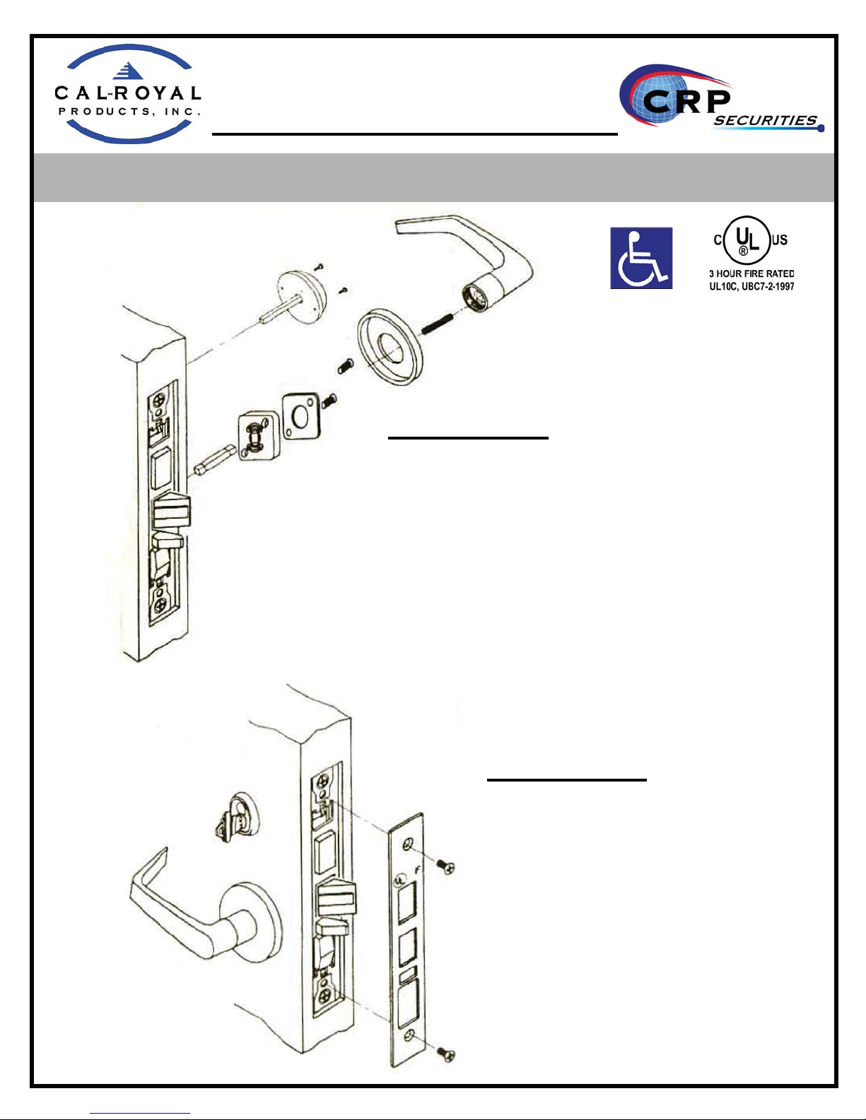
Inside Lever
1. Insert spindle into hub of lock case.
2. Place spring cage with arrows pointing in
direction of lever rotation and mounting
plate (spring-mount assembly) onto lock
case and fasten into screws.
3. Cap inside rose over spring-mount assembly.
4. Insert inside spring into lever hole and
tighten inside lever bushing with spanner
wrench.
5. Insert turn piece assembly and fasten with
screws.
Front Plate
1. Install outside front plate onto
lockcase front and then fasten
with screws.
Page 2
M SERIES
Heavy Duty Mortise Lock
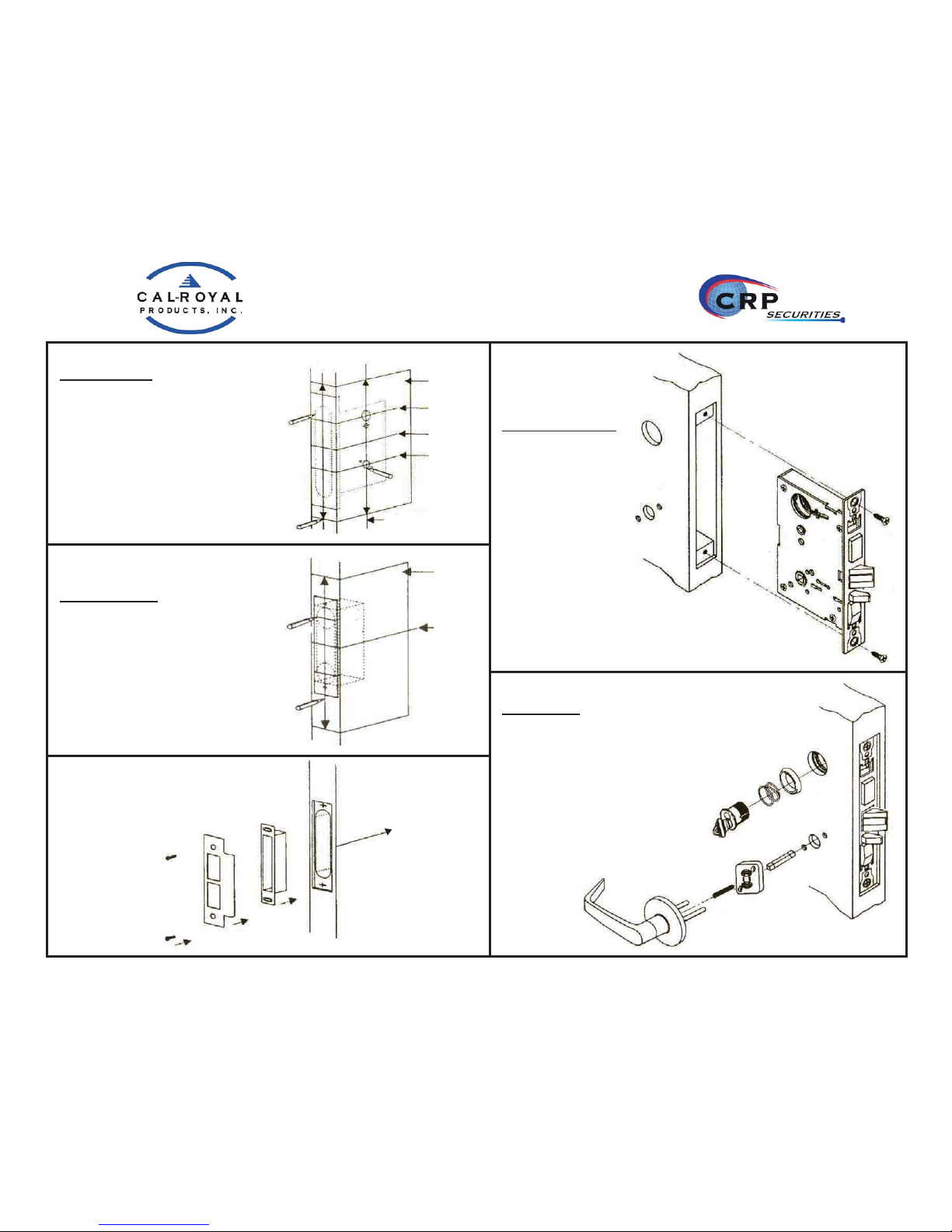
Door Preparation
1. Align door preparation template on
edge of door with applicable lines.
Check door preparation chart and
mark only holes for lock function
being installed.
2. Mortise door edge according to
measurements of installation
template and drill proper holes for
trims.
Strike preparation
1. Align strike template on jamb
according to measurements of strike
installation template.
Bore 1” diameter holes into door
edge, 1 1/8” deep. Recess 5/32” for t
of strike and box.
2. Mortise jamb according to measurement
of installation template. Then t strik
and dust box into frame and secure into
place with screws.
Outside lever
1. Place spring cage onto outside lever
assembly with arrows pointing in
direction of lever rotation. Insert
spindle into hub of lock case.
2. Position outside lever assembly into
post holes of lock case.
Lockcase Installation
1. Insert lockcase into
mortise cut-out & fasten
screws to door.
Installation
Template
C
L
C
L
C
L
of Front
Plate
of Lever
of Cylinder
Installation
Template
C
L
of Front
Plate
C
L
of Front
Plate
Vertical Line
of Lever
1-1/8”
Depth
3 -3/4”
Height
Page 3
M SERIES
Heavy Duty Mortise Lock
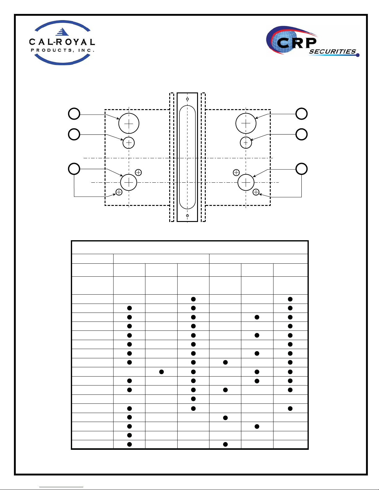
1-1/4” DIA
CYLINDER HOLE
3/4” DIA
B
THUMBTURN
HOLE
C
L
of Lock
C
C
of Lever
L
3/8” DIA
SERIES
LOCK
FUNCTION
NM8010
NM8050
NM8453
NM8070
NM8456
NM8080
NM8485
NM8466
NM8040
NM8473
NM8060
NM8170
M8465
M8462
M8460
M8464
M8463
LOCK
CASE
MORTISE
C
L
1-1/4” DIA
CYLINDER HOLE
3/4” DIA
THUMBTURN
HOLE
C
of Lock
L
1” DIA1” DIA
LEVER HOLELEVER HOLE
C
of Lever
L
3/8” DIA
THRU HOLETHRU HOLE
DOOR PREPARATION CHART
CYLINDER
HOLE
OUTSIDE
THUMBTURN
HOLE
LEVER HOLE
CYLINDER
HOLE
INSIDE
THUMBTURN
HOLE
LEVER HOLE
ABCABC
AA
B
C
Page 4
M SERIES
Heavy Duty Mortise Lock
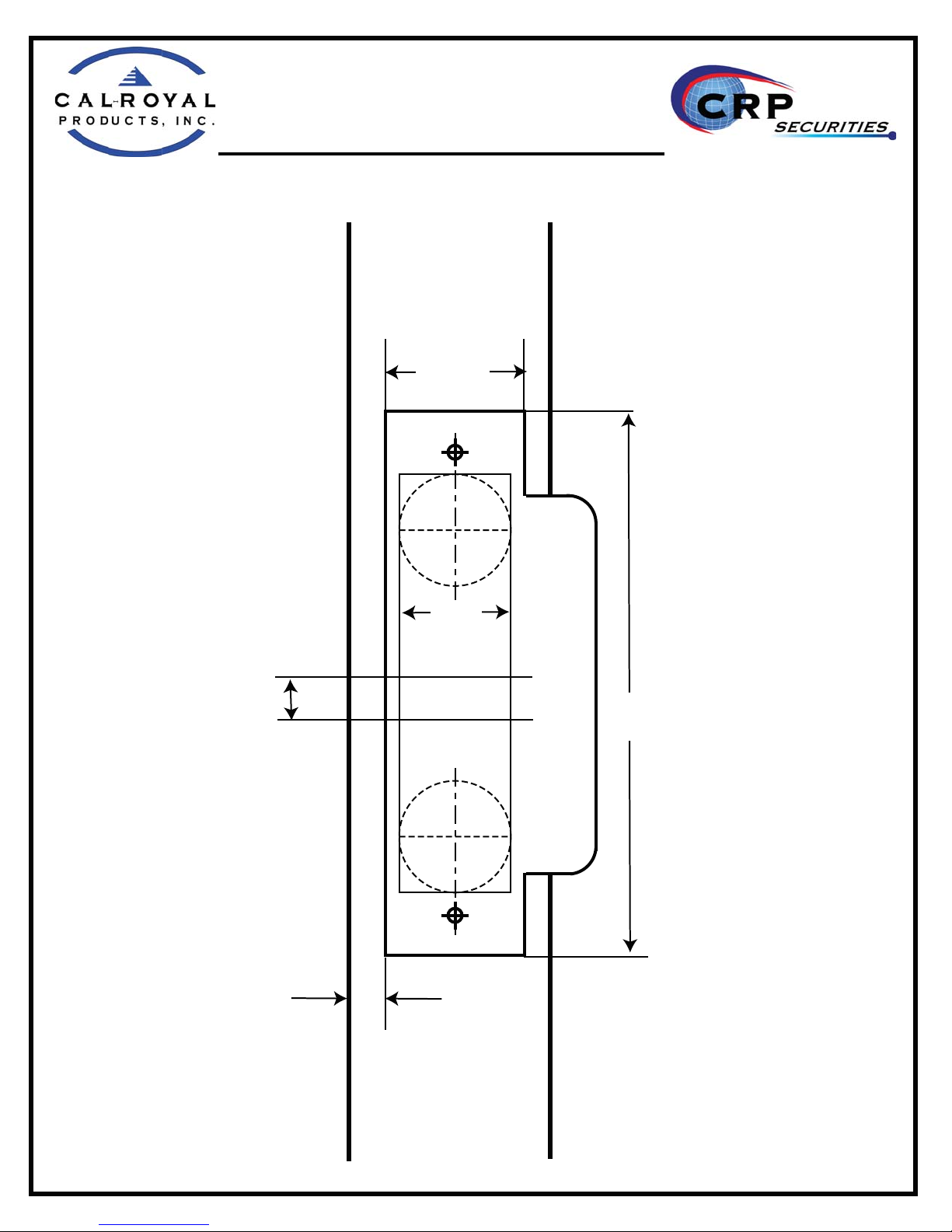
STRIKE TEMPLATE
1-1/4”
C
L
STRIKE
LOCK
C
L
1”
1-1/8”
DEEP
3/8”
4-7/8”
HEIGHT
1-5/8”
5/16”
DOOR FRAME
VIEW
 Loading...