


Pompe sommergibili per acque sporche
Submersible Sewage and Drainage Pumps
Schmutzwasser-Tauchmotorpumpen
Pompes submersibles pour eaux chargées
Bombas sumergibles para aguas sucias
Dränkbara länspumpar
Rioolwater-drainage dompelpompen
Хрпвсэчйет бнфлЯет бкбиЬсфщн кбй лхмЬфщн
огружные насосы длЯ грЯзной воды
GX 40, GM 50
ISTRUZIONI ORIGINALI PER L’USO Pagina 2 Italiano
ORIGINAL OPERATING INSTRUCTIONS Page 6 English
ORIGINAL BETRIEBSANLEITUNG Seite 10 Deutsch
INSTRUCTIONS ORIGINALES POUR L’UTILISATION
Page 14 Français
INSTRUCCIONES ORIGINALES DE USO Página 18 Español
ORIGINAL DRIFT/INSTALLATIONSANVISNINGAR
Sidan 22 Svenska
ORIGINEEL BEDIENINGSVOORSCHRIFT Pagina 26 Nederlands
ППДДЗЗГГЙЙЕЕУУ ЧЧЕЕЙЙССЙЙУУММППХ
Õ
УелЯдб
30
ЕллзнйкЬ
нструкции по эксплуатации òð. 34
усский
GM 50GX 40 GM 50-65

Pompe sommergibili per acque
sporche
GX 40, GM 50
ISTRUZIONI PER L’USO
1. Denominazione della pompa
Vedere la denominazione indicata nella targa sulla
pompa oppure nell’etichetta con il codice a barre.
Significato delle sigle:
GX 40 =
Pompa in acciaio inossidabile con bocca
di mandata G 1
1
/2ISO 228 (DN 40).
GM 50 = Pompa in ghisa con bocca di
mandata G 2 ISO 228 (DN 50).
GM 50-65= Pompa in ghisa con bocca di
mandata flangiata (DN 65).
C = Con girante bicanale (GXC) o
monocanale (GMC).
V = Con girante arretrata (a vortice).
M = Con motore monofase (senza
indica-zione = con motore trifase).
2. Condizioni d’impiego
Esecuzione standard
- Per acqua pulita e per acque sporche anche
con corpi solidi fino ad un diametro di:
35 mm per GX 40;
45 mm per GMC ..; 50 mm per GMV ...
Con
elevato contenuto di corpi solidi o con fibre
lunghe impiegare solo le esecuzioni con girante
arretrata (a vortice) GXV e GMV.
-
Massima temperatura del liquido: 35 °C.
- Massima densità del liquido: 1100 kg/m
3
.
- Dimensioni minime pozzetto d’installazione:
0,55x0,55 m; profondità 0,5 m.
- Minima profondità di immersione:
250 mm per GX 40;
180 mm per GM 50.
-
Massima profondità di immersione: GX 40 = 5 m;
GM 50 = 10 m (con cavo di adatta lunghezza).
-
Avviamenti/ora max: 30 ad intervalli regolari.
Pressione sonora con la minima profondità di
immersione: < 70 dB (A).
La rumorosità scompare con la pompa sommersa.
Non usare la pompa su stagni,
vasche da giardino, piscine, quando
nell’acqua si trovano persone.
La pompa non può essere usata in un
ambiente esplosivo o infiammabile.
3. Installazione
Il diametro interno del tubo di mandata non deve mai
essere inferiore al diametro della bocca della pompa:
G 11/2(DN 40) per GX 40;
G 2 (DN 50) per GM 50.
(DN 65) per GM 50-65.
La pompa deve essere sollevata e trasportata
servendosi dell’apposita maniglia e mai del cavo
elettrico di alimentazione.
Appoggiare la pompa, con asse verticale, sul
fondo del pozzetto o del luogo di installazione.
3.1. Installazione fissa
Nelle installazioni fisse, montare nel tubo di
mandata una valvola di non ritorno contro il riflusso.
Prevedere che sia possibile la rimozione della
pompa senza svuotare l’impianto (se necessario,
inserire una saracinesca ed un bocchettone).
Con la pompa appoggiata, prevedere ancoraggi e
sostegni del tubo di mandata adatti alla sua
lunghezza e peso.
Se si prevede che sul fondo del pozzetto possa
formarsi della melma di deposito prevedere
opportuno appoggio che mantenga l’elettropompa
sollevata.
3.2. Installazione trasportabile
Fissare sempre una fune o catena di sicurezza,
di materiale non deperibile, alla pompa.
Se si usa un tubo di mandata flessibile o in
plastica, utilizzare la fune di sicurezza per
abbassare, ancorare e sollevare la pompa.
2
3.93.037/3
GX = 250
G
M
= 180
GX = 450
G
M
= 500
3.93.037/3
Avviamento
Arresto

Non usare mai il cavo elettrico per
sostenere la pompa.
Fissare il cavo di alimentazione al tubo di
mandata o alla fune di sicurezza con fascette.
Lasciare allentato il cavo elettrico per evitare tensioni
causate dalle dilatazioni del tubo sotto carico.
3.3. Installazione con scivolo di
accoppiamento per GM.. 50-65
Il sistema di accoppiamento automatico consente
lavori di ispezione rapidi e razionali.
Il piede di accoppiamento viene fissato sul fondo
del pozzetto assieme alla tubazione di mandata;
due tubi di guida lo collegano alla staffa di
ancoraggio fissata al bordo della botola.
La pompa viene calata lungo i tubi di guida fino a
raggiungere la posizione esatta per
l’accoppiamento; la tenuta risulterà perfetta
grazie al peso stesso della pompa.
Questa operazione può essere ripetuta
innumerevoli volte e facilita particolarmente i
lavori di controllo e di ispezione; la pompa viene
semplicemente estratta dal pozzetto con una
catena (anche in caso di impianto allagato)
4. Collegamento elettrico
Il collegamento elettrico deve essere
eseguito da un elettricista qualificato nel
rispetto delle prescrizioni locali.
Seguire le norme di sicurezza.
Eseguire sempre il collegamento a terra della
pompa, anche con tubo di mandata non
metallico.
Verificare che la frequenza e la tensione di rete
corrispondano a quelle indicate in targa.
Per l’uso in una piscina (solamente quando
all’interno non vi sono persone), vasche da giardino
o posti similari, nel circuito di alimentazione deve
essere installato un interruttore differenziale con
una corrente residua (I∆N)
≤ 30 mA.
Installare un dispositivo per la onnipolare
disinserzione dalla rete (interruttore per
scollegare la pompa dall’alimentazione) con una
distanza di apertura dei contatti di almeno 3 mm.
Nel caso di prolunghe assicurarsi che il cavo sia
di adeguata sezione per evitare cadute di
tensione e che la giunzione rimanga all’asciutto.
4.1. Pompe monofasi GXCM, GXVM
Sono fornite con
termoprotettore
incorporato, con
cavo di
alimentazione tipo
H07 RN8-F, 4G1 mm
2
e con interruttore a
galleggiante.
A richiesta viene
fornita la scatola di
comando con
condensatore.
Schema di
collegamento
4.2. Pompe monofasi GMCM, GMVM
Sono fornite con condensatore e termoprotettore
incorporati, con cavo di alimentazione tipo H07
RN8-F, 3G1,5 mm
2
con spina e con interruttore a
galleggiante.
4.3. Pompe trifasi GXC, GXV
Installare nel quadro di comando un adeguato
salvamotore come da corrente di targa.
4.4. Pompe trifasi GMC, GMV
Sono dotate di 2
ter
moprotettori
collegati in serie
ed inseriti entro 2 fasi diverse.
I ter
moprotettori
, nei motori trifasi, proteggono dal
sovraccarico e non dalla marcia a motore bloccato.
Il quadro di comando deve prevedere quindi anche
idoneo relè termoamperometrico accoppiato al
contattore di comando.
Seguire lo schema elettrico sottoriportato
Con le elettropompe trifasi, quando non é
possibile controllare a vista il livello dell’acqua,
per proteggere la pompa contro il funzionamento
a secco e per stabilire i livelli di arresto e di
avviamento automatico, installare un interruttore
a galleggiante collegato al quadro di comando.
3
4
.93.002/2
M
1
nero
grigio (blu)
marrone
verde/giallo
4.93.002/3
verde/giallo
nero
blu
marrone
grigio
grigio
Motore
3 ~ 220-240 V
3 ~ 380-415 V
Ai morsetti di potenza
del contattore
Te r
moprotettori
da
collegare alla bobina
del contattore

4
5. Avviamento
Con alimentazione trifase verificare che il
senso di rotazione sia corretto.
Prima dell’installazione, avviare per pochi giri il
motore e controllare attraverso l’apertura di
aspirazione che la girante giri nel senso indicato
dalla freccia sulla pompa. In caso contrario
togliere l’alimentazione elettrica e invertire fra loro
i collegamenti di due fasi nel quadro di comando.
Il funzionamento con senso di rotazione inverso é
causa di vibrazioni e perdita di portata. La rotazione
inversa é dannosa anche per la tenuta meccanica.
Nel caso di incertezza occorre estrarre la pompa
e controllare il senso di rotazione osservando
direttamente la girante.
Non introdurre dita nell’apertura di
aspirazione se non si é accertato che
sia tolta l’energia elettrica (che la
pompa non rischi di essere messa sotto
tensione per inavvertenza) e che la girante si sia
completamente arrestata.
I motori collegati direttamente alla rete tramite
interruttori termici possono avviarsi
automaticamente.
Non estrarre mai dall’acqua la pompa quando
questa è ancora in funzione.
Evitare il funzionamento a secco.
Esecuzione con galleggiante:
l’interruttore a galleggiante collegato direttamente
alla pompa comanda l’avviamento e l’arresto
della stessa.
Controllare che l’interruttore a galleggiante non
trovi impedimenti al libero galleggiamento.
Se necessario, regolare la lunghezza del cavo
del galleggiante (fissare la lunghezza con la vite
96.09). Il cavo del galleggiante troppo lungo può
provocare il surriscaldamento del motore ed il
funzionamento a secco della pompa.
Esecuzione senza galleggiante:
avviare la pompa solo se immersa almeno
250 mm (GX
40) o 180 mm (GM 50) nel liquido
da sollevare.
6. Manutenzione
Nelle condizioni d’impiego normali la pompa non
richiede manutenzioni.
Nel caso di pericolo di gelo, se la pompa rimane
inattiva e se non è sufficientemente sommersa,
estrarla dall’acqua e sistemarla all’asciutto.
Nel caso di impieghi temporanei con liquidi
incrostanti (liquidi con parti che solidificano quando
sono esposte all’aria in condizioni stagnanti) o
acqua con cloruri, subito dopo l’uso lavare la
pompa con acqua per rimuovere i depositi.
Dopo lunga inattività, se la pompa non si avvia o
non dà acqua e non risultano interruzioni nel
collegamento elettrico occorre estrarre la pompa
e verificare che non sia ostruita da impurità,
bloccata da incrostazioni o da altre cause.
AVVERTENZE PER LA SICUREZZA, L’IGIENE E
LA PROTEZIONEDELLA SALUTE SUL LAVORO.
Prima di ogni intervento di
manutenzione togliere l’alimentazione
elettrica e assicurarsi che la pompa
non rischi di essere messa sotto
tensione per inavvertenza.
La pompa può essere stata immersa in
prodotti nocivi o esalanti gas tossici,
oppure trovarsi in ambiente tossico per
altre cause; usare tutte le precauzioni
necessarie per evitare incidenti.
Eventuali pompe da ispezionare o riparare
prima della spedizione/messa a disposizione
devono essere svuotate e accuratamente
pulite internamente ed esternamente.
Lavare con getto d’acqua tutte le parti accessibili.
Per evitare il rischio di lesioni
meccaniche od elettriche
tutte le pompe portatili
devono essere scollegate in
modo sicuro dall’alimentazione elettrica prima
della loro rilocazione (cambio di posto o
spostamento).
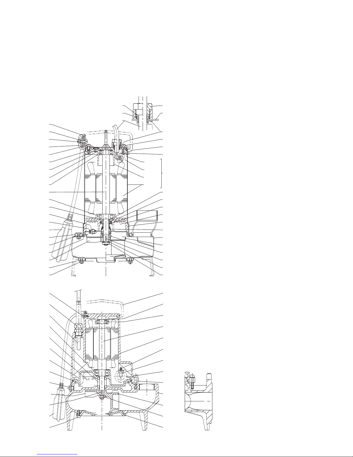
7. Smontaggio
Per lo smontaggio ed il rimontaggio osservare la
costruzione sul disegno in sezione.
Per l’ispezione della girante (28.00), la pulizia
delle parti interne e per controllare manualmente
la libera rotazione della girante, togliere i dadi
(GX) o le viti (GM) pos. 12.20 ed il coperchio del
corpo (12.00). Per rimuovere la girante togliere il
dado (28.04).
Usare i fori filettati di estrazione con la girante GMV.
Evitare lo smontaggio di altre parti.
Ogni manomissione può compromettere la
funzionalità della pompa.
Se è necessario ispezionare la tenuta meccanica
(36.00) e la camera olio, osservare le seguenti
istruzioni.
ATTENZIONE: la camera d’olio può
essere in leggera pressione.
Usare la necessaria precauzione per
evitare spruzzi.
Tolto il tappo (14.46) con guarnizione (14.47)
orientare il foro verso il basso e svuotare
accuratamente la camera.
Non disperdere l’olio usato nell’ambiente.
Togliendo la linguetta (28.20), le viti (14.24) ed il
corpo pompa (14.00), diventa ispezionabile la
tenuta meccanica (36.00).
Per il riempimento con nuovo olio tenere
presente che la camera non deve essere
completamente riempita ma in essa deve
rimanere un’adeguata quantità d’aria per

5
Nr. Denominazione
12.00 Coperchio del corpo
12.20
Vite
12.21 Dado
14.00 Corpo pompa
14.20 Guarnizione corpo
14.22 Anello di fissaggio
14.24 Vite
14.46 Tappo
14.47 Guarnizione
28.00 Girante
28.04 Dado bloccaggio girante
28.08 Rosetta
28.20 Linguetta
36.00 Tenuta meccanica
40.00 Anello di tenuta radiale
64.08 Camicia di protezione
64.12 O-ring
70.00 Coperchio motore lato pompa
70.05 O-ring
70.11 Anello del pressacavo (galleggiante)
70.12 Anello del pressacavo
70.13 Rondella
73.00 Cuscinetto lato pompa
73.08 V-Ring
76.00 Carcassa motore con avvolgimento
76.01 Camicia motore con avvolgimento (1)
76.02 Camicia mtore completa
76.04 Anello pressacavo
76.60 Galleggiante
76.62 Coperchio camicia
76.63 Vite
76.64 Maniglia
76.65 Staffa per maniglia
76.66 Rosetta
78.00 Albero con pacco rotore
78.12 O-ring
81.00 Cuscinetto
82.01 Coperchio motore lato opposto (1)
82.02 Vite
82.03 O-ring
82.04 Molla di compensazione
82.05 Vite (1)
94.00 Condensatore
94.04 Collare condensatore
96.00 Cavo
96.07 Blocca cavo
96.08 Staffa
96.09 Vite
96.10 Dado
(1) Non fornibile separatamente
(2) Olio
(3) Grasso
Disegni in sezione
3.94.024.1
(1)
(2)
GMC
GMV 50-65
GMC 50-65
GMV
76.64
64.08
36.00
14.00
28.00
28.20
28.08
28.04
64.12
76.63
82.03
82.02
82.04
81.00
78.00
73.00
14.46
14.47
14.22
14.24
14.20
28.00
12.00
96.07
96.09
96.10
96.08
76.63
40.00
76.60
76.62
76.04
96.00
70.12
70.13
70.05
76.65
12.21
70.00
76.01
82.01
82.05
78.12
76.02
70.11
76.66
73.08
GXV
GXC
3.94.035
(1)
(1)
(2)
(3)
(1)
4.94.061
96.08
76.04
96.00
73.00
36.00
70.00
14.20
14.46
28.00
28.20
76.60
12.20
76.64
82.04
81.00
78.00
76.00
94.12
94.04
94.00
14.24
14.00
28.00
28.04
12.00
96.09
compensare le sovrapressioni dovute alla
dilatazione termica dell’olio.
La quantità d’olio da immettere nella camera è di:
0,2 litri per GX 40;
0,5 litri per GM 50.
Usare olio bianco per uso alimentare-farmaceutico.
Per le GM 50 si può usare anche un normale olio
per motori SAE 10W-30
8. Richieste e ricambi
Ad ogni richiesta e nelle eventuali ordinazioni
indicare i dati di targa oppure i numeri riportati
nell’etichetta con il codice a barre o allegare una
fotocopia di questa.
Per i ricambi precisare la denominazione ed il
numero di posizione nel disegno in sezione.
Con riserva di modifiche.

6
Submersible sewage and
drainage pumps
GX 40, GM 50
OPERATING INSTRUCTIONS
1. Pump designation
See designation on the pump name-plate or on
the bar-code label.
Meaning of the designations:
GX 40 = Stainless steel pump with G 1
1
/
2
ISO 228 (DN 40) delivery connection.
GM 50 = Cast iron pump with G 2 ISO 228
(DN 50) delivery connection.
GM 50-65= Cast iron pump with (DN 65)
flanged delivery connection.
C = With two- (GXC) or single-passage
(GMC) impeller.
V = With free-flow (vortex) impeller.
M = With single-phase motor (without
indication = with three-phase motor).
2. Operating conditions
Standard construction
- For clean and dirty water, also containing solids
with maximum size:
35 mm for GX 40;
45 mm for GMC ..; 50 mm for GMV ....
With a high solid content or with filamentous par
ticles use only the free-flow (vortex) GXV and
GMV construction.
-
Maximum liquid temperature: 35 °C.
- Maximum liquid density: 1100 kg/m
3
.
- Minimum dimensions of installation pit:
0.55x0.55m; depth 0.5 m.
- Minimum immersion depth:
250 mm for GX 40;
180 mm for GM 50.
- Maximum submersion depth: GX 40 = 5 m;
GM 50 = 10 m (with suitable cable length).
-
Maximum starts/hour: 30 at regular intervals.
Sound pressure at minimum immersion depth:
< 70 dB (A).
Noise disappears when the pump is submersed.
Do not use in garden ponds, tanks or
swimming pools when people are in the
water.
The Pump cannot be used in
explosive or flammable environments.
3. Installation
The internal diameter of the delivery pipe must never be
smaller than the diameter of the pump connection port:
G 11/2(DN 40) for GX 40;
G 2 (DN 50) for GM 50;
(DN 65) for GM 50-65.
The pump must be lifted and transported using
the handle fitted for this purpose and not pulled
by the electrical power cable.
Place the pump, with vertical axis, at the bottom
of the pit or at the site of installation.
3.1. Stationary installation
For stationary installation fit a check valve against
back flow in the delivery pipe.
Provide for the possibility of removing the pump
without having to drain the entire system (if
necessary, fit a gate valve and a union coupling).
With the pump in the resting position secure the
delivery pipe to a rest, suitable for its length and
weight.
If slime deposits are expected to form at the
bottom of the installation pit, a support must be
provided to keep the pump raised.
3.2. Transportable installation
A safety rope or chain of non-perishable material
should always be used to secure the pump.
When a plastic or flexible delivery pipe is used,
the safety rope or chain should be utilized for
lowering, securing and raising the pump.
3.93.037/3
GX = 250
G
M
= 180
GX = 450
G
M
= 500
3.93.037/3
On
Off

7
Never use the electric power cable to
suspend the pump.
Attach the power supply cable to the delivery pipe
or to the safety rope with cable clamps.
The
power cable should not be taut: allow for a certain
degree of slackness to avoid the risk of strain
caused by expansion of the pipe during
operation.
3.3. Fixed installation with automatic
coupling feet and guide rails.
The automatic coupling system allows for quick
and efficient inspection operations.
The coupling foot is fastened to the bottom of the
sump together with the delivery pipe; two guiding
tubes connect it to the anchoring bracket secured
to the edge of the sump cover.
The pump is lowered along the guiding tubes until
it reaches the exact coupling position; the seal
will be tight thanks to the weight of the pump.
This operation can be repeated any number of
times and it makes checking and inspection
operations easier; the pump is simply extracted
from the sump by means of a chain (even if the
system is flooded).
4. Electrical connection
Electrical connection must be carried
out only by a qualified electrician in
accordance with local regulations.
Follow all safety standards.
The unit must be always earthed, also with a
non-metallic delivery pipe.
Make sure the frequency and mains voltage
correspond with the name plate data.
For use in swimming pools (not when persons are
in the pool), garden ponds and similar places, a
residual current device with I∆N not exceeding
30 mA
must be installed in the supply circuit.
Install a device for disconnection from the
mains (switch) with a contact separation of at
least 3 mm on all poles.
When extension cables are used, make sure the
cable wires are of adequate size to avoid voltage
drops and that the connection stays dry
.
4.1. Single-phase pumps GXCM, GXVM
Supplied with
incorporated thermal
protector, with
power cable type
H07 RN8-F, 4G1 mm
2
and with float
switch.
Control box with
capacitor supplied
on request.
Electrical diagram
4.2. Single-phase pumps GMCM, GMVM
Supplied with incorporated capacitor and thermal
protector, with power cable type H07 RN8-F,
3G1.5 mm
2
with plug and float switch.
4.3. Three-phase pumps GXC, GXV
Install in the control box an overload-protective
device in accordance with the name-plate current.
4.4. Three-phase pumps GMC, GMV
Fitted with 2
thermal pro
tectors
which are connected
in series and inserted between two different phases.
The
thermal pro
tectors
, in the three-phase motors,
provide protection against overloading and not
against operation with a blocked rotor.
The control box must therefore also be fitted with
a suitable hot-wire ammeter relay cuopled with
the control contactor.
Follow the electrical circuit diagram indicated below
With three-phase pumps, when the water level is
not under direct visible control, install a float
switch connected to the control box to protect the
pump against dry running and to set the water
levels to stop and automatically start the pump.
green/yellow
black
blue
maroon
grey
grey
Motor
3 ~ 220-240 V
3 ~ 380-415 V
To the terminal connection
points of the contactor
Thermal pro
tectors
to connect to the
contator coil
4.93.002/2
M
1
black
grey (blue)
maroon
green/yellow
4.93.002/3

8
5. Starting
With a three-phase power supply make sure
the direction of rotation is correct.
Before installation, momentarily start the motor to
check through the suction opening that the
rotation of the impeller is as shown by the arrow
on the pump. Otherwise disconnect electrical
power and reverse the connections of two phases
in the control box.
Operation with wrong direction of rotation will
cause vibration and loss of delivery capacity
.
Reverse rotation can also demage the
mechanical seal.
When in doubt, take the pump out of the water
and check rotation of the impeller by sight.
Never introduce fingers in the
suction opening unless it is absolutely
certain the electric power has been
disconnected (that the pump cannot be
accidentally switched on) and the impeller has
stopped rotating completely
.
The motors with supply current directly
switched by thermally sensitive switches can
start automatically
.
Never take the pump out of the water while the
pump is still operating.
Avoid running dry.
Construction with float switch:
the float switch, connected directly to the pump,
controls starting and stopping.
Check that the float switch is free from any obstacle.
If necessary, adjust the float-switch cable (secure
the length with screw 96.09).
Execessive cable length may cause the motor to
overheat and the pump to run dry.
Construction without float switch:
start the pump only if immersed at least 250 mm (GX
40) or 180 mm (GM 50) in the liquid to be raised.
6. Maintenance
Under normal operating conditions the pump will
not require maintenance.
If freezing may be expected while the pump remains inactive and it is not submersed at a safe
depth, remove the pump from the water and
leave in a dry place.
If the pump is temporarily used with incrusting
liquids (prone to crystallization or liquids with
particles that solidify when exposed to air in
stagnant conditions) or water containing
chloride, flush the pump briefly with water
immediately after use to remove any deposit.
If the pump has not been used for a long time and
does not start or gives no water (but electrical
connections are in order), the pump must be
removed from the water and checked to see if it is
choked by any foreign matter or blocked by
sediment, deposits or any other cause.
INSTRUCTIONSFOR SAFETY, HYGIENE AND
HEALTH PROTECTION AT WORK.
Disconnect electrical power before
any servicing operation and make
sure the pump cannot be
accidentally switched on.
The pump may have been immersed
in hazardous substances or products
emanating toxic gases, or may be
located in an environment which is
toxic due to other reasons; make sure all
necessary precautionary measures are taken
to avoid accidents.
Any pumps that require inspection/repair
must be drained and carefully cleaned inside
and outside before dispatch/submission.
Hose down all accessible parts with a jet of water.
In order to avoid the risk of
mechanical or electrical injury
all portable pumps should be
securely isolated from electrical
power supply prior to their relocation.
7. Dismantling
For disassembly and reassembly, refer to the
cross-section drawing.
To inspect the impeller (28.00), to clean the
internal parts and to check whether the impeller
turns freely when moved by hand, remove the
nuts (GX) or the screws (GM) (12.20) and casing
cover (12.00).
To dismantle the impeller remove the nut (28.04).
Use the threaded dismantling holes to remove
the GMV impeller.
Others parts should not be dismantled.
The pump function can be impaired by erroneous procedure or tampering with internal parts.
If the mechanical seal (36.00) and the oil chamber
are to be inspected, follow these instructions.
CAUTION: there may be slight
pressure in the oil chamber.
Care must be taken to avoid a sudden
spurting of oil.
Once the plug (14.46) with washer (14.47) have
been removed, adjust the hole to the downward
position and empty the chamber completely.
Do not dispose of the waste oil in the
enviroment.
The mechanical seal (36.00) can be inspected by
removing the impeller key (28.20), the screws
(14.24) and the pump casing (14.00).
When re-filling with fresh oil, remember that the
chamber must not be completely filled; a
suf
ficient quantity of air must remain inside it in
order to compensate for overpressure caused by

9
Cross section drawings
Nr. Designation
12.00 Casing cover
12.20
Screw
12.21 Nut
14.00 Pump casing
14.20 Casing gasket
14.22 Fastening ring
14.24 Screw
14.46 Plug
14.47 Gasket
28.00 Impeller
28.04 Impeller nut
28.08 Washer
28.20 Key
36.00 Mechanical seal
40.00 Radial shaft seal
64.08 Shaft sleeve
64.12 O-ring
70.00 Motor cover, pump side
70.05 O-ring
70.11 Cable gland ring (float switch)
70.12 Cable gland ring
70.13 Washer
73.00 Pump side bearing
73.08 V-Ring
76.00 Motor casing with winding
76.01 Motor jacket with winding (1)
76.02 Kit, motor jacket
76.04 Cable gland
76.60 Float switch
76.62 Jacket cover
76.63 Screw
76.64 Handle
76.65 Handle clamp
76.66 Washer
78.00 Shaft with rotor packet
78.12 O-ring
81.00 Bearing
82.01 Motor end-shield, non-drive end (1)
82.02 Screw
82.03 O-ring
82.04 Compensating spring
82.05 Screw (1)
94.00 Capacitor
94.04 Capacitor collar
96.00 Cable
96.07 Cable fastener
96.08 Clamp
96.09 Screw
96.10 Nut
(1) Cannot be supplied separately
(2) Oil
(3) Grease
thermic dilation of the oil.
The quantity of oil to be inserted in the chamber is:
0.2 litres for GX 40;
0.5 litres for GM 50.
Use white oil suitable for food machinery and
pharmaceutic use.
For the GM 50 pumps a normal engine oil of the
SAE 10W
-30 type can also be used.
8. Queries and spare parts
In your queries and orders please mention the
pump name-plate data. Alternatively, if the bar-code
label has been saved, mention the numbers on the
label or enclose a photocopy of it.
When ordering spare parts quote part
designations and drawing position numbers.
Changes reserved.
3.94.024.1
(1)
(2)
GMC
GMV 50-65
GMC 50-65
GMV
76.64
64.08
36.00
14.00
28.00
28.20
28.08
28.04
64.12
76.63
82.03
82.02
82.04
81.00
78.00
73.00
14.46
14.47
14.22
14.24
14.20
28.00
12.00
96.07
96.09
96.10
96.08
76.63
40.00
76.60
76.62
76.04
96.00
70.12
70.13
70.05
76.65
12.21
70.00
76.01
82.01
82.05
78.12
76.02
70.11
76.66
73.08
GXV
GXC
3.94.035
(1)
(1)
(2)
(3)
(1)
4.94.061
96.08
76.04
96.00
73.00
36.00
70.00
14.20
14.46
28.00
28.20
76.60
12.20
76.64
82.04
81.00
78.00
76.00
94.12
94.04
94.00
14.24
14.00
28.00
28.04
12.00
96.09

10
SchmutzwasserTauchmotorpumpen
GX 40, GM 50
BETRIEBSANLEITUNG
1. Pumpenbezeichnung
Siehe Bezeichnung auf dem Pumpen-Typenschild
oder auf dem Strichkode-Etikett.
Bedeutung der Kennzeichnung:
GX 40 = Edelstahlpumpe mit Druckstutzen
G 1
1
/2ISO 228 (DN 40).
GM 50 = Graugußpumpe mit Druckstutzen
G 2 ISO 228 (DN 50).
GM 50-65= Graugußpumpe mit Druckstutzen
(DN 65).
C = Mit Zweikanalrad (GXC) oder
Einkanalrad (GMC).
V = Mit Freistromrad.
M = Mit einphasigem Wechselstrommotor
(ohne
Angabe = mit Drehstrommotor).
2. Anwendungsbereich
Standardausführung
- Für reines und verschmutztes Wasser, auch mit
Festbestandteilen bis Korngröße:
35 mm für GX 40;
45 mm für GMC ..; 50 mm für GMV ...
Für Flüssigkeiten mit hohen Anteilen von festen und
langfaserigen Beimengungen ist nur die Ausführung
mit Freistromrad GXV und GMV zu verwenden.
- Mediumstemperatur bis 35 °C.
- Maximale Mediumsdichte: 1100 kg/m
3
.
Platzbedarf: Grundfläche mind. 0,55x0,55 m;
Tiefe 0,5 m.
- Mindest-Eintauchtiefe:
250 mm für GX 40;
180 mm für GM 50.
-
Maximale Eintauchtiefe: GX 40 = 5 m;
GM 50 = 10 m (bei geeigneter Kabellänge).
- Maximale Anlaufszahl pro Stunde: 30
gleichmäßig verteilte Starts.
Schalldruck bei Mindest-Eintauchtiefe: < 70 dB (A).
Die Pumpe arbeitet bei Überflutung geräuschlos.
Die Pumpe darf nie in Teichen, Becken
oder Schwimmbädern eingesetzt
werden, in denen sich Personen
befinden.
Die Pumpe darf nicht in einem
explosionsgefährdeten oder
entzündbaren Umfeld eingesetzt werden.
3. Aufstellung
Der Innendurchmesser der Förderleitung darf
nicht kleiner sein als der Pumpenanschluß:
G 1
1
/2(DN 40) für GX 40;
G 2 (DN 50) für GM 50.
(DN 65) für GM 50-65.
Beim
Transport der Pumpe ist der Tragegriff zu
verwenden. Auf keinen Fall darf die Pumpe an
dem Elektrokabel gehoben werden.
Die Pumpe ist im Sumpf und am Installationsort
in senkrechter Position aufzustellen.
3.1. Stationäre Aufstellung
Bei stationärer Aufstellung ist in der Druckleitung
ein Rückschlagventil einzubauen, um den
Wasserrückfluß zu verhindern.
Pumpe so einbauen, daß Abnahme ohne
Entleerung der druckseitingen Anlage möglich ist
(ggfs. Schieber und Überwurfmutter einbauen).
Mit der Pumpe auf dem Boden stehend, die
Förderleitung ist je nach Länge und Gewicht mit
geeigneten Mitteln zu befestigen.
Sofern Schlamm-Ablagerungen auf dem
Schachtboden zu erwarten sind, ist die Pumpe
auf eine erhöhte Grundplatte aufzustellen, um
oberhalb der Ablagerungen frei laufen zu können.
3.2. Transportable Aufstellung
Es wird empfohlen, immer ein Halte- oder
Sicherungsseil oder eine Sicherungskette aus
unzerstörbarem Material an der Pumpe zu befestigen.
Wenn ein Kunststoffrohr oder ein Schlauch als
3.93.037/3
GX = 250
G
M
= 180
GX = 450
G
M
= 500
3.93.037/3
Ein
Aus

11
Druckleitung verwendet wird, ist das
Sicherungsseil zum Absenken, Befestigen oder
Hochziehen der Pumpe zu verwenden.
Auf keinen Fall darf die Pumpe an
dem Elektrokabel gehoben werden.
Das Elektrokabel ist mit Manschetten an
der Druckkleitung oder am Sicherungsseil zu
befestigen. Das Elektrokabel sollte Spielraum
zwischen den Manschetten haben, um
Spannungen durch die
Ausdehnung des unter
Belastung stehenden Rohrs zu vermeiden.
3.3.Stationäre Nassaufstellung mit
Kupplungs- und Führungssystem
Dank dem automatischen Kupplungssystem kann
die Pumpe rasch und wirksam kontrolliert werden.
Der Kupplungsfuß wird, gemeinsam mit der
Druckleitung, auf dem Grund des Gullies
befestigt. Zwein Führungsrohre verbinden den
Stützfuß mit dem am Rand der Klappe
befestigten Verankerungsbügel.
Die Pumpe wird längs des bzw. der
Führungsrohre
abgesenkt, bis die genaue Kupplungsposition erreicht
ist; die Dichtigkeit wird durch das Eigengewicht der
Pumpe selbst versichert.
Dieser Vorgang kann beliebig oft wiederholt
werden und erleichtert insbesondere alle
Wartungs-und Kontrolleingriffe. Die Pumpe wird
ganz einfach mittels einer Kette aus dem Gully
geholt (auch bei Überflutung der Anlage)
4. Elektrischer Anschluß
Der elektrische Anschluß ist von
Fachpersonal unter Beachtung der
örtlichen Vorschriften auszuführen.
Sicherheitsvorschriften befolgen.
Die Pumpe muß immer
, auch mit nicht
metallischer Druckleitung, an die Erdung
angeschlossen werden.
Frequenz und Netzspannung mit den Angaben
auf dem
Typenschild vergleichen.
Die Benutzung in Schwimmbecken, Gartenteichen
und ähnlichen Orten ist nur zulässig, wenn sich
keine Personen im Wasser befinden und wenn die
Pumpe an einem Schaltkreis angeschlossen ist, der
durch eine Fehlerstrom-Schutzeinrichtung mit
einem Nennfehlerstrom (I
∆N)
≤ 30 mA geschützt ist.
Es ist eine Vorrichtung zur Abschaltung jeder
Phase vom Netz (Schalter) mit einem Öffnungs-
abstand
der Kontakte von mindestens 3 mm zu
installieren.
Bei Kabelverlängerungen versichern Sie sich,
daß der Kabelquerschnitt geeignet ist, um eine
Spannungssenkung zu vermeiden.
Die
Verlängerungsverbindungen müssen trocken bleiben.
4.1. Einphasen-Wechselstrompumpen
GXCM, GXVM
Diese Pumpen
werden mit
eingebautem
Thermoschalter,
mit Kabel Typ
H07 RN8-F, 4G1
mm
2
und mit
Schwimmerschalter
geliefert.
Ein Schaltkasten mit
Anlaufkondensator
wird auf Anfrage
geliefert.
Schaltbild
4.2. Einphasen-Wechselstrompumpen
GMCM, GMVM
Diese Pumpen sind mit Anlaufkondensator,
Thermoschutz, Schwimmerschalter, Stecker und
Anschluß-kabel HO7 RN8-F, 3G1,5 mm
2
ausgestattet.
4.3. Dreiphasen-Drehstrompumpen
GXC, GXV
Bei diesen Pumpen ist ein Motorschutzschalter
gemäß der Stromaufnahme laut Typenschild im
Schaltkasten einzubauen.
4.4. Dreiphasen-Drehstrompumpen
GMC, GMV
Diese Pumpen sind mit 2 Mikro-Thermoschaltern
ausgestattet, die in Reihe geschaltet und
zwischen 2 Phasen eingesetzt sind.
Diese Thermoschalter schützen nur vor
Überlastung, aber nicht bei blockiertem Motor. Im
Schaltkasten sind deshalb ausreichend
ausgelegte Überstromschutzrelais zu installieren.
Folgendes Schaltbild befolgen:
Bei Dreiphasen-Drehstrompumpen muß ein am
Schaltkasten angeschlossener Schwimmerschalter
eingebaut werden, wenn der Wasserspiegel nicht
direkt auf Sicht kontrolliert werden kann, um die
Pumpe vor Trockenlauf zu schützen und um die
grün/gelb
schwarz
blau
braun
grau
grau
Motor
3 ~ 220-240 V
3 ~ 380-415 V
Zu den Anschlußstellen
der Stromversorgung
Zum Schutzrelais für
Thermo-Schutzschalter
4.93.002/2
M
1
schwarz
grau (blau)
braun
grün/gelb
4.93.002/3

12
Wasserstände zur automatischen Ein- und
Ausschaltung festzulegen.
5. Inbetriebnahme
Bei DreiphasenDrehstromversorgung ist die
Drehrichtung zu überprüfen.
Vor der Installation den Motor kurz
einschalten und durch die Saugöf
fnung prüfen,
ob die Laufrad-Drehrichtung mit dem Pfeil auf der
Pumpe übereinstimmt. Andernfalls die
Netzversorgung abschalten und zwei beliebige
Phase im Schaltkasten vertauschen.
Der Betrieb bei falscher Drehrichtung verursacht
Vibrationen und Förderstromabnahme.
Die umgekehrte Drehung ist auch für die
Gleitringdichtung schädlich.
Bei Ungewißheit muß man die Pumpe aus dem
Wasser ziehen und die Drehrichtung direkt auf
das Laufrad überprüfen.
Keinen Finger in die Saugöffnung einführen,
wenn sich nicht versichert wurde, daß der Strom
abgeschaltet ist (daß die Pumpe nicht aus
Unachtsamkeit unter Spannung gesetzt werden
kann) und daß das Laufrad vollständig stillsteht.
Die Motoren, deren Versorgungsspannung durch
temperaturabhängige Schalter direkt geschaltet
wird, können gegebenenfalls selbsttätig anlaufen!
Niemals die Pumpe bei Betrieb aus dem Wasser ziehen.
Die Pumpe darf nicht trocken laufen.
Ausführung mit Schwimmerschalter:
Der angeschlossene Schwimmerschalter schaltet
die Pumpe ein und aus.
Vergewissern Sie sich, daß der Schwimmerschalter
keine Hindernisse für die Schwimmbewegung findet.
Falls erforderlich, muß man die Länge des
Schwimmerchalterkabels einstellen (dabei Länge
mit Schraube 96.09 befestigen).
Ein zu langes Schwimmerschalterkabel kann die
Überhitzung des Motors und den Trockenlauf der
Pumpe verursachen.
Ausführung ohne Schwimmerschalter:
Die Pumpe darf nur eingeschaltet werden, wenn
sie mindestens 250 mm (GX 40) oder 180 mm
(GM 50) im Wasser eingetaucht ist.
6. Wartung
Unter normalen Einsatzbedingungen ist die Pumpe
wartungsfrei.
Wenn die Pumpe nicht eingesetzt wird und wenn sie
nicht ausreichend überflutet ist, ist sie bei Frostgefahr
aus dem Wasser zu ziehen und trocken zu lagern.
Bei gelegentlichen Einsätzen mit Verkrustung bildenden bzw.
verklebenden Medien (Flüssigketien mit Bestandteilen, die
erstarren wenn bei stillstehender Lage an die Luft gebracht
werden) oder Wasser mit Chloriden ist die Pumpe anschließend
mit Wasser zur Beseitigung von Schmutzansammlungen,
Anbackungen und Rückstände abzuwaschen.
Wenn die Pumpe nach längerem Stillstand nicht
startet bzw. kein Wasser gibt und keine Unterbrechung
des elektrischen Anschlusses vorliegt, muß die Pumpe
gehoben werden, um zu kontrollieren, ob sie nicht
durch Verunreinigungen verstopft bzw. durch
Ablagerungen oder andere Ursachen blockiert ist.
VORSCHRIFTEN FÜR SICHERHEIT,
HYGIENE UND ARBEITSSCHUTZ.
Alle Arbeiten am Aggregat nur bei
abgeschalteter Stromzufuhr
durchführen und sich versichern, daß
die Pumpe nicht aus Unachtsamkeit
unter Spannung gesetzt werden kann.
Die Pumpe könnte in
gesundheitsgefährdenden bzw.
giftige Gase ausströmenden Fluiden
eingesetzt worden sein. Ebenso
können sich aus sonstigen Gründen in dem
Austellungsort der Pumpe gefährliche Stoffe
angereichert haben. Deshalb sind alle
möglichen Sicherheitsmaßnahmen zu
ergreifen, um Unfällezu vermeiden.
Wenn Pumpen zu inspektionieren oder reparieren
sind, müssen diese vor Versand/Bereitstellung
entleert sowie außen und innen sorgfältig
gereinigt werden.
Alle zugänglichen Teile sind mit einem starken
Wasserstrahl zu reinigen.
Zur Vermeidung von mechanisch
oder elektrisch bedingten
Verletzungen ist bei allen tragbaren
Pumpen vor dem Umsetzen die
Stromversorgung sicher zu unterbrechen.
7. Demontage
Demontage und Montage unter Zuhilfenahme
des Schnittbildes durchführen.
Zur Inspektion des Laufrades (28.00), zur
Reinigung der Innenteile und um zu überprüfen,
ob das Laufrad sich leicht von Hand drehen läßt,
Muttern (GX) bzw. Schrauben (GM) Pos. Nr.
12.20 lösen und Gehäusedeckel (12.00)
abnehmen. Zum Abziehen des GMV-Laufrades
Abziehgewindelöcher benutzen.
Die Demontage von anderen
Teilen ist zu
vermeiden. Jede unbefugte Demontage kann
die Pumpe beeinträchtigen.
Bei einer eventuell notwendigen Überprüfung der
Gleitringdichtung (36.00) und der Ölkammer sind
folgende V
orschriften zu beachten.
VORSICHT: Es kann ein leichter
Überdruck in der Ölkammer bestehen.
Vorsichtsmaßnahmen gegen mögliches
Ölausspritzen vornehmen.
Nach Lösen der Verschlußschraube (14.46) mit
Dichtring (14.47) ist die Öffnung nach unten zu
richten und die Ölkammer leerlaufen zu lassen.
Das alte Öl ist ordnungsgemäß zu entsorgen.
Nach Abnahme der Paßfeder (28.20) der Schrauben
(14.24) und des Pumpengehäuses (14.00) kann die
Gleitringdichtung (36.00) überprüft werden.
Bei Auffüllung mit frischem Öl ist zu beachten,
daß die Kammer nicht vollständig gefüllt sein
darf. Ein Luftpolster muß erhalten bleiben, um

13
Schnittzeichnungen
Nr. Teile-Benennung
12.00 Gehäusedeckel
12.20
Schraube
12.21 Mutter
14.00 Pumpengehäuse
14.20 Gehäusedichtung
14.22 Verbindungsring
14.24 Schraube
14.47 Dichtring
14.46 Verschlußschraube
28.00 Laufrad
28.04 Laufradmutter
28.08 Scheibe
28.20 Paßfeder
36.00 Gleitingdichtung
40.00 Radialdichtring
64.08 Wellenschutzhülse
64.12 Runddichtring
70.00 Motorlagergehäuse, pumpensei
tig
70.05 Runddichtring
70.11 Kabelring (Schwimmerschalter)
70.12 Kabelring
70.13 Scheibe
73.00 Wälzlager, pumpenseitig
73.08 V-Ring
76.00 Motorgehäuse mit Wicklung
76.01 Motormantel mit Wicklung (1)
76.02 Teil-Motormantel, komplett
76.04 Kabelführung
76.60 Schwimmerschalter
76.62 Manteldeckel
76.63 Schraube
76.64 Griff
76.65 Schelle für Griff
76.66 Scheibe
78.00 Welle mit Rotorpaket
78.12 Runddichtring
81.00 Wälzlager
82.01 Motorlagergehäuse, B-seitig (1)
82.02 Schraube
82.03 Runddichtring
82.04 Federscheibe
82.05 Schraube (1)
94.00 Kondensator
94.04 Kondensatorschelle
96.00 Kabel
96.07 Kabelhalterung
96.08 Schelle
96.09 Schraube
96.10 Mutter
(1) Nicht getrennt lieferbar
(2) Öl
(3) Fett
einen Überdruck durch Erwärmung des Öls
auszugleichen.
Die genauen Einfüllwerte sind:
0,2 Liter für GX 40;
0,5 Liter für GM 50.
Nur W
eißöl für Nahrungsmittelmaschinen und
Pharmazeutik verwenden.
Für GM 50 können auch handelsübliche Motorenöle
des Typs SAE 10W-30 verwendet werden.
8. Rückfragen und Ersatzteile
Bei Rückfragen und bei einer eventuellen
Bestellung bitten wir Typenschild-Daten oder die
Nummern auf dem Strichkode-Etikett anzugeben
oder eine Photokopie davon beizulegen.
Bei Ersatzteil-Bestellung bitte Teile-Benennung
und Teile-Nummer laut Schnittzeichnung angeben.
Änderungen vorbehalten.
3.94.024.1
(1)
(2)
GMC
GMV 50-65
GMC 50-65
GMV
76.64
64.08
36.00
14.00
28.00
28.20
28.08
28.04
64.12
76.63
82.03
82.02
82.04
81.00
78.00
73.00
14.46
14.47
14.22
14.24
14.20
28.00
12.00
96.07
96.09
96.10
96.08
76.63
40.00
76.60
76.62
76.04
96.00
70.12
70.13
70.05
76.65
12.21
70.00
76.01
82.01
82.05
78.12
76.02
70.11
76.66
73.08
GXV
GXC
3.94.035
(1)
(1)
(2)
(3)
(1)
4.94.061
96.08
76.04
96.00
73.00
36.00
70.00
14.20
14.46
28.00
28.20
76.60
12.20
76.64
82.04
81.00
78.00
76.00
94.12
94.04
94.00
14.24
14.00
28.00
28.04
12.00
96.09

14
Pompes submersibles pour
eaux chargées
GX 40, GM 50
INSTRUCTIONS POUR L’UTILISATION
1. Désignation de la pompe
Voir la désignation sur la plaque signalétique ou
sur l’étiquette avec le code barre.
Signification de les sigles:
GX 40 =
Pompe en acier inoxydable avec orifice
de refoulement G 1
1
/2ISO 228 (DN 40).
GM 50 = Pompe en fonte avec orifice de
refoulement G 2 ISO 228 (DN 50).
GM 50-65= Pompe en fonte avec orifice de
refoulement (DN 65).
C = Avec roue bicanaux (GXC)ou
monocanal
(GMC).
V = Avec roue tourbillon (vortex).
M = Avec moteur monophasé (sans
indication = avec moteur triphasé).
2. Conditions d’utilisation
Exécution normale
- Pour eaux propres et pour eaux chargées, avec
parties solides jusqu’à un diamètre de:
35 mm pour GX 40;
45 mm pour GMC ..; 50 mm pour GMV ...
Pour le pompage d’eaux très chargées ou avec
fibres longues utiliser les pompes avec turbines
vortex (GXV, GMV).
-
Température maximum du liquide: 35 °C.
- Densité maximum du liquide: 1100 kg/m3.
- Dimensions minimum du puits d’installation:
0,55x0,55 m; profondeur 0,5 m
- Profondeur minimum d’immersion:
250 mm pour GX 40;
180 mm pour GM 50.
-
Profondeur maximum d’immersion: GX 40 = 5 m;
GM 50 = 10 m (avec un câble de longueur suffisante).
-
Démarrages/heure maximum: 30, à intervalles réguliers.
Pression acoustique avec profondeur minimum
d’immersion: < 70 dB (A).
Le bruit disparait avec la pompe submergée.
Ne pas utiliser la pompe en étangs,
bassins de jardin,
piscines où se
trouvent des personnes.
La pompe ne peut pas être utilisée
dans une ambiance explosive ou
inflammable.
3. Installation
Le diamètre intérieur du tube de refoulement ne peut
être inférieur au diamètre de l’orifice de la pompe:
G 11/2(DN 40) pour GX 40;
G 2 (DN 50) pour GM 50.
(DN 65) pour GM 50-65.
Le pompe doit être suolevée et transportée à
l’aide de la poignée prévue à cet ef
fet et jamais
par le câble électrique d’alimentation.
Placer la pompe verticalement sur le fond du
puits ou du lieu d’installation.
3.1. Installation stationnaire
Dans les installations stationnaires, monter dans
le tuyau de refoulement un clapet de retenue
pour empêcher le retour de l’eau.
Prévior que le relevage de la pompe est possible
sans vider toute l’installation (si nécessaire, installer
une vanne de fermeture et un union 3 pièces).
Avec la pompe posée, prévoir la fixation du tuyau de
refoulement approprié d’après le poids et la longueur.
Si des dépôts de vase sont susceptibles de se
former au fond de la fosse d’installation, il faut
prévoir un support pour surélever la pompe.
3.2. Installation transportable
Attacher toujours la pompe par un câble ou
chaîne de sécurité, inattaquable par le milieu
d’immersion.
Si vous utilisez un tuyau de refoulement flexible
ou en matière plastique, servez vous du câble de
3.93.037/3
GX = 250
G
M
= 180
GX = 450
G
M
= 500
3.93.037/3
Marche
Arrêt

15
sécurité pour descendre, ancrer et soulever la
pompe.
Le câble électrique ne doit jamais
être utilisé pour tenir la pompe.
Fixer le câble d’alimentation au tuyau de
refoulement ou au câble de sécurité au moyen de
colliers. Veuillez à ce que le câble électrique reste
détendu entre les colliers, pour éviter les tensions
occasionnées par la dilatation du tuyau en charge.
3,2. PInstallation fixe avec pied
d’assise et barres de guidage.
Le système d'assemblage automatique permet des
opérations d'inspection rapides et rationnelles.
Le pied d'assemblage est fixé sur le fond du
puisard, avec la canalisation de refoulement.
Deux tubes de guidage le relient à la bride
d'ancrage fixée sur le bord de la trappe.
La pompe est descendue le long des tubes de
guidage jusqu'à atteindre la position précise pour
l'assemblage. L'étanchéité sera parfaite grâce au
seul poids de la pompe.
Cette opération peut être répétée de nombreuses
fois et facilite particulièrement les travaux de
contrôle et d'inspection; la pompe est simplement
retirée du puisard à l'aide d'une chaîne (même
dans le cas d'une installation immergée)
4. Connexion électrique
La connexion électrique doit être
exécutée par un spécialiste suivant les
prescriptions locales.
Suivre les normes de sécurité.
Exécuter toujours la mise à la terre de la pompe,
même avec tuyau de refoulement non métallique.
Comparer la fréquence et la tension du réseau
avec les données de la plaque signalétique.
Pour l’usage dans une piscine (seulement quand
il n’y a personne à l’interieur), bassins de jardin
ou endroits analogues, installer un disjoncteur
différentiel de courant de déclenchement
nominal (I
∆N) ne dépassant pas 30 mA.
Installer un dispositif pour débrancher chaque
phase du réseau (interrupteur pour déconnecter
la pompe de l’alimentation) avec une distance
d’ouverture des contacts d’au moins 3 mm.
Dans le cas de prolongement de câble, s’assurer
que la section convient pour éviter des chutes de
tension et que la jonction reste au sec.
4.1. Pompes monophasées
GXCM, GXVM
Ces pompes sont
équipées d’une
protection thermique
incorporée, câble
d’alimentation de
type H07 RN8-F,
4 G 1 mm
2
et avec
interrupteur à flotteur.
Un coffret de contrôle
aveccondensateur
est livré surdemande.
Schéma électrique
4.2. Pompes monophasées
GMCM, GMVM
Ces pompes sont équipées d’un condensateur
intégré et d’un dispositif de protection thermique
avec câble d’alimentation de type H07 RN8-F,
3G1,5 mm
2
avec fiche et interrupteur à flotteur.
4.3. Pompes triphasées GXC, GXV
Installer dans le coffret de commande une
protection moteur appropriée, conformément au
courant figurant sur la plaque signalétique.
4.4. Pompes triphasées GMC, GMV
Les moteurs triphasés sont équipés de deux
protecteurs
thermiques
qui sont montés en série
et insérés entre deux phases différentes.
Les protecteurs
thermiques
, dans les moteurs
triphasés, donnent une protection contre la
surchage et non contre un fonctionnement avec
un rotor bloqué. Le coffret de commande doit par
conséquent comprendre aussi un relais
thermique couplé au contacteur de commande.
Suivre le schéma électrique ci après.
Avec les pompes triphasées, en cas d’impossibilité
de contrôler visuellement le niveau d’eau, pour
protéger la pompe contre tout fonctionnement à
sec, pour fixer le niveaux d’arrêt et de mise en
route automatique, installer un interrupteur à
flotteur connecté au coffret de commande.
vert/jaune
noir
bleu
marron
gris
gris
Moteur
3 ~ 220-240 V
3 ~ 380-415 V
Vers les points de
connexion du contacteur
Protecteurs thermiques
vers la bobine
du contacteur.
4
.93.002/2
M
1
noir
gris (bleu)
marron
vert/jaune
4.93.002/3

16
5. Démarrage
En cas d’alimentation triphasée,
vérifier que le sens de rotation est
correct.
Avant l’installation, démarrer pendant
quelques tours le moteur et vérifier à travers
l’ouverture d’aspiration que, le sens de rotation de
la roue soit le même que celui indiqué par la
flèche sur la pompe. Dans le cas contraire,
débrancher l’alimentation électrique et inverser les
connexions des deux phases dans le coffret de
commande.
Le fonctionnement avec rotation inverse entraine
des vibrations et une perte de débit.
La rotation inverse est nuisible pour la garniture
mécanique.
En cas d’incertitude du sens de rotation sortir la
pompe et vérifier la rotation de la roue.
Ne pas introduire un doigt dans l’ouverture
d’aspiration avant de vous être assuré de la
déconnection de l’alimentation électrique (que la
pompe ne risque pas d’être mise sous tension
par inadvertance) et que la roue ait totalement
arreté de tourner
.
Les moteurs dont l’alimentation en courant est
directement commutée par des interrupteurs
thermiques peuvent démarrer automatiquement.
Ne jamais retirer la pompe de l’eau avant l’arrêt complet.
Eviter le fonctionnement à sec.
Exécution avec interrupteur à flotteur:
l’interrupteur à flotteur relié directement à la pompe
commande la mise en route et l’arrêt de celle-ci.
Contrôler que l’interrupteur à flotteur flotte librement.
Si nécessaire régler la longueur du câble du flotteur
(fixer la longueur avec la vis 96.09). Un flotteur
réglé trop bas peut provoquer l’échauffement du
moteur et le fonctionnement à sec de la pompe.
Exécution sans interrupteur à flotteur:
ne démarrer la pompe que lorsqu’elle est
immergeé au moins 250 mm (GX 40) ou 180 mm
(GM 50) dans le liquide à pomper
.
6. Entretien
Dans des conditions normales d’utilisation, la
pompe n’exige aucun entretien.
En cas de crainte de gel, si la pompe doit rester
inutilisée, et surtout si celle ci n’est pas
suffisamment immergée, il est nécessaire de la
retirer de l’eau et de la ranger dans un endroit sec.
En cas d’utilisation occasionnelle avec des
liquides incrustants (liquides avec particules qui
se solidifient lorsqu’elles sont exposées à l’air dans
des conditions stagnantes) ou si l’eau contient
des chlorures, il est nécessaire de rincer la pompe
immédiatement après utilisation avec de l’eau pour
enlever les encrassements et toute trace de dépôt.
Après un arrêt prolongé, si la pompe ne démarre
pas ou ne débite pas et si, après vérification,
aucune discontinuité n’est constatée au niveau
du raccordement électrique, il est nécessaire
d’extraire la pompe pour vérifier si aucune
impureté, dépôt calcaire, ou autres, n’entrave pas
son fonctionnement.
AVERTISSEMENTS POUR LA SECURITE,
L
’HYGIENE ET LA PROTECTION DE LA
SANTE SUR LE TRAVAIL.
Avant toute opération d’entretien
débrancher l’alimentation
électrique et s’assurer que la pompe
ne risque pas d’être mise sous
tension par inadvertance.
Il se peut que la pompe ait été
immergée dans des produits
chimiques agressifs ou des
produits dégageant des gaz
toxiquesou bienelle peut être située
dans un milieu qui est toxique pour d’autres
raisons. S’assurer que toutes les précautions
nécessaires ont été prises pour éviter tout
accident.
En cas d’inspection ou réparation, avant
son exepédition/sa mise en disponibilité, la
pompe doit être soigneusement vidangée et
nettoyée intérieurement et extérieurement.
Laver toutes les parties accessibles au jet d’eau.
Afin d’eviter tout risque de
blessures mécaniques ou
électriques toutes les pompes
portatives doivent être
debranchées de l’alimentation électrique avant
tout deplacement.
7. Démontage
Pour le démontage et le remontage, observer la
construction sur le dessin en coupe.
Pour l’inspection de la roue (28.00), le nettoyage
des parties à l’intérieur et pour contrôler que la
roue tourne librement à la main, enlever l’ecroux
(GX) ou le vis (GM) pos. 12.20 et le couvercle du
corps (12.00).
Pour extraire la roue enlever l’ecrou (28.04).
Pour extraire la roue GMV utiliser les trous filetés
prévus à cet effet.
Eviter le démontage d’autres piéces.
Tout démontage ou remontage incorrect pourrait
compromettre le bon fonctionnement de la pompe.
S’il est nécessaire inspecter la garniture
mécanique (36.00) et la chambre à huile, suivre
les instructions suivantes.
ATTENTION: la chambre d’huile peut
être légèrement sous pression.
Veillez à éviter les projections d’huile.
Une fois le buochon (14.46) avec joint (14.17)
retirés, orienter le trou vers le bas et vider
complètement la chambre d’huile.
Ne pas jeter l’huile usagée en milieu naturel.
En enlevant la clavette (28.20) les vis (14.24) et
le corps de pompe (14.00) on peut inspecter la
garniture mécanique (36.00).
Au remplissage avec de l’huile neuve, ne pas oublier
que le réservoir ne doit pas être complètement rempli;
il faut laisser à l’intérieur une quantité suffisante d’air
afin de compenser la surpression provoquée par la

17
Dessins en coupe
Nr. Description
12.00 Couvercle du corps
12.20
Vis
12.21 Ecrou
14.00 Corps de pompe
14.20 Joint du corps de pompe
14.22 Anneau de fixation
14.24 Vis
14.46 Bouchon
14.47 Joint
28.00 Roue
28.04 Ecrou de blocage de roue
28.08 Rondelle
28.20 Clavette
36.00 Garniture mécanique
40.00 Joint à lèvres
64.08 Chemise d’arbre
64.12 Joint torique
70.00 Fond de moteur, côté pompe
70.05 Joint torique
70.11 Bague du câble (interrupteur à flotteur)
70.12 Bague de câble
70.13 Rondelle
73.00 Roulement à billes, côté pompe
73.08 V-Ring
76.00 Carcasse moteur avec bobinage
76.01 Chemise moteur avec bobinage (1)
76.02 Ensemble carcasse moteur
76.04 Bague de serrage de câble
76.60 Interrupteur à flotteur
76.62 Couvercle chemise
76.63 Vis
76.64 Poignée
76.65 Bride de poignée
76.66 Rondelle
78.00 Arbre-rotor
78.12 Joint torique
81.00 Roulement à billes
82.01 Fond de moteur, côté opposé (1)
82.02 Vis
82.03 Joint torique
82.04 Rondelle de compensation
82.05 Vis (1)
94.00 Condensateur
94.04 Fouloir
96.00 Câble
96.07 Pièce de fixation câble
96.08 Bride
96.09 Vis
96.10 Ecrou
(1) Ne peut être livré séparément
(2) Huile
(3) Graisse
dilatation thermique de l’huile.
La quantité correcte d’huile à mettre dans le
réservoir est de:
0,2 litres pour GX 40;
0,5 litres pour GM 50.
N’utiliser que de l’huile blanche à usage
alimentaire ou pharmaceutique.
Pour les GM 50 on peut utiliser une huile à
moteur normal de type SAE 10W
-30.
8. Demandes et pièces de rechange
Sur chaque demande et pour toutes commandes,
mentionner les données de la plaque signalétique
ou indiquer les numéros de l’etiquette avec le code
barre au bien fournir une photocopie de celle ci.
Pour pièces de rechange, indiquer leur
dénomination et le numéro du repère sur le
dessin en coupe.
Sous réserve de modifications.
3.94.024.1
(1)
(2)
GMC
GMV 50-65
GMC 50-65
GMV
76.64
64.08
36.00
14.00
28.00
28.20
28.08
28.04
64.12
76.63
82.03
82.02
82.04
81.00
78.00
73.00
14.46
14.47
14.22
14.24
14.20
28.00
12.00
96.07
96.09
96.10
96.08
76.63
40.00
76.60
76.62
76.04
96.00
70.12
70.13
70.05
76.65
12.21
70.00
76.01
82.01
82.05
78.12
76.02
70.11
76.66
73.08
GXV
GXC
3.94.035
(1)
(1)
(2)
(3)
(1)
4.94.061
96.08
76.04
96.00
73.00
36.00
70.00
14.20
14.46
28.00
28.20
76.60
12.20
76.64
82.04
81.00
78.00
76.00
94.12
94.04
94.00
14.24
14.00
28.00
28.04
12.00
96.09

Bombas sumergibles para
aguas sucias
GX 40, GM 50
INSTRUCCIONES DE USO
1. Denominación de la bomba
Ver la denominación indicada en la placa de la bomba
o bien en la etiqueta con el código de barras.
Significado de las siglas
GX 40 = Bomba en acero inoxidable con boca
de impulsión G1
1
/2ISO 228 (DN 40).
GM 50 = Bomba en hierro de fundición gris
con boca de impulsión de G 2 ISO
228 (DN 50).
GM 50-65= Bomba en hierro de fundición gris
con boca de impulsión de (DN 65).
C = Con rodete bicanal (GXC) o
monocanal (GMC).
V = Con rodete tipo vórtice.
M = Con motor monofásico (sin
indicación = con motor trifásico).
2. Condiciones de empleo
Ejecución standard
- Para agua limpia y para aguas sucias incluso
con cuerpos sólidos hasta un diámetro de:
35 mm. para GX 40;
45 mm. para GMC ..; 50 mm para GMV ...
Con elevado contenido de cuerpos sólidos o
con fibras largas emplear solo la ejecución con
rodete vórtice GXV y GMV.
- Máxima temperatura del líquido: 35 °C.
- Máxima densidad del líquido: 1100 kg/m
3
.
- Dimensión mínima de foso de la instalación:
0,55x0,55m; profundidad 0,5 m.
- Mínima profundidad de inmersión:
250 mm. para GX 40;
180 mm. para GM 50.
- Máxima profundidad de inmersión: GX 40 = 5 m;
GM 50 = 10 m (con cable de longitud adecuada).
-
Arranques/hora máx.: 30 en intervalos regulares.
Presión acústica con la mínima profundidad de
inmersión: < 70 dB (A).
El ruido desaparece con la bomba sumergida.
No usar la bomba en estanques,
balsas, piscinas, cuando en el agua
se encuentren personas.
La bomba no puede ser usada en un
ambiente explosivo o inflamable.
3. Instalación
El diámetro interior del tubo de impulsión no debe ser
nunca inferior al diámetro de la boca de la bomba:
G 11/2(DN 40) para GX 40;
G 2 (DN 50) para GM 50.
(DN 65) para GM 50-65.
La bomba debe ser elevada y transportada
sirviéndose de la propia asa y nunca del cable
eléctrico de alimentación.
Apoyar la bomba, con el asa vertical, sobre el
fondo del pozo o del lugar de la instalación.
3.1 Instalación fija
En las instalaciones fijas, montar en el tubo de
impulsión una válvula de retención. Prever que
sea posible el movimiento de la bomba sin vaciar
la instalación (sí es necesario instalar una válvula
y un tapón).
Con la bomba asentada, prever anclajes y
apoyos del tubo de impulsión adaptados a su
longitud y peso.
Si prevé que sobre el fondo de la fosa puedan
formarse lodos de sedimentos prever el oportuno
apoyo que mantenga la electrobomba sobre elevada.
3.2 Instalación transportable
Fijar siempre una cuerda o una cadena de
seguridad, de material no perecedero, a la
bomba. Si se usa un tubo de impulsión flexible o
de plástico, utilizar el cable de seguridad para
18
3.93.037/3
GX = 250
G
M
= 180
GX = 450
G
M
= 500
3.93.037/3
Arranque
Paro

descender, anclar y elevar la bomba.
No usar nunca el cable eléctrico para
sostener la bomba.
Fijar el cable de alimentación al tubo de
impulsión o al cable de seguridad con bridas.
Dejar flojo (sin tensar) el cable eléctrico para
evitar tensiones a causa de las dilataciones del
tubo bajo carga.
3,2. Iinstalación fija con dispositivo
de acoplamiento de fondo
El sistema de acoplamiento automático permite
trabajos de inspección rápidos y racionales.
El pie de acoplamiento se fija en el fondo del
sumidero junto con la tubería de impulsión; dos
tubos de guía lo conectan al estribo de anclaje
fijado en el borde de la trampilla.
La bomba se baja a lo largo de los tubos de guía hasta
alcanzar la posición exacta para el acoplamiento; la
fijación será perfecta gracias al peso de la bomba.
Esta operación puede repetirse varias veces y facilita
los trabajos de control e inspección: la bomba se
extrae del sumidero simplemente con una cadena
(también en el caso de instalación inundada).
4. Conexión eléctrica
El conexionado eléctrico debe ser
realizado por un electricista cualificado,
respetando las prescripciones locales.
Seguir las normas de seguridad.
Realizar siempre el conexionado a tierra de la
bomba, incluso con el tubo de impulsión no
metálico.
Verificar que la frecuencia y las tensiones de la
red se corresponden a las indicadas en la placa
de características.
Para el uso en una piscina (solamente cuando en
el interior no hay personas), balsas de jardín o
sitios similares, en el circuito de alimentación
debe ser instalado un interruptor diferencial con
una corriente residual (I
∆N) ≤ 30 mA.
Instalar un dispositivo para la total desconexión
de la red (interruptor para desconectar la bomba
de la alimentación eléctrica) con una distancia de
apertura de los contactos de al menos 3 mm.
En el caso de prolongamientos asegurarse que el
cable eléctrico sea de la adecuada sección para
evitar caídas de tensión y que la conexión
permanezca en ambiente seco.
4.1. Bombas monofásicas GXCM, GXVM
Son suministradas
con termoprotector
incorporado, con
cable de
alimentación tipo
H07 RN8-F, 4G1 mm
2
y con interruptor de
nivel.
Bajo demanda se
suministra una caja
de mando con el
condensador.
Esquema de conexionado.
4.2. Bombas monofásicas GMCM, GMVM
Se suministran con condensador y termoprotector
incorporado, con cable de alimentación tipo H07
RN8-F, 3G1,5 mm
2
con conector e interruptor de
nivel.
4.3. Bombas trifásicas GXC, GXV
Instalar en el cuadro de mando un adecuado
salva motor según la corriente de la placa de
características.
4.4. Bombas trifásicas GMC, GMV
Están dotadas de dos termoprotectores
conexionados en serie entre dos fases distintas.
Los termoprotectores, en los motores trifásicos,
protegen de sobrecargas pero no de la marcha
con motor bloqueado. El cuadro de mando debe
prever por consiguiente un idóneo relé termo
amperimétrico acoplado al contactor de mando.
Seguir el esquema eléctrico siguiente
Con las electrobombas trifásicas, cuando no es
posible controlar visualmente el nivel del agua,
para proteger la bomba contra el funcionamiento
en seco y para establecer los niveles de paro y
arranque automáticamente, instalar un interruptor
de nivel conexionado al cuadro de mando.
19
4
.93.002/2
M
1
negro
gris (azul)
marrón
verde/amarillo
4.93.002/3
verde/amarillo
negro
azul
marrón
gris
gris
Motor
3 ~ 220-240 V
3 ~ 380-415 V
A los bornes de
potencia del contactor
Termoprotectores
a
conectar a la bobina
del contactor
20
5. Arranque
Con alimentación trifásica verificar
que el sentido de giro sea el correcto.
Antes de la instalación, arrancar con
pocas vueltas el motor y controlar a
través de la apertura de aspiración que el rodete
gire en el sentido indicado de la flecha sobre la
bomba. En caso contrario sacar la alimentación
eléctrica e invertir entre ellos en conexionado de
dos fases en el cuadro de mando.
El funcionamiento con el sentido de rotación
invertido es causa de vibraciones y pérdida de
caudal. La rotación inversa es dañosa incluso
para el cierre mecánico.
En el caso de inseguridad es necesario sacar la
bomba y controlar el sentido de giro observando
directamente el rodete.
No introducir los dedos en la apertura de la
aspiración si no está completamente seguro que
la bomba esté desconectada de la energía eléctrica
(además de que no haya el riesgo de que la
electrobomba quede bajo tensión accidentalmente)
y que el rodete esté completamente parado.
Los motores conexionados directamente a la
red eléctrica por medio de interruptores
térmicos, pueden arrancar automáticamente.
No sacar nunca la bomba del agua cuando esté
todavía en funcionamiento.
Evitar en funcionamiento en seco.
Ejecución con interruptor de nivel:
El interruptor de nivel conectado directamente a
la bomba controla el arranque y paro de la misma.
Controlar que el interruptor de nivel no encuentre
impedimentos a su libre flotación.
Si es necesario, regular la longitud del cable del
interruptor (fijar la longitud con el tornillo 96.09).
El cable del interruptor demasiado largo puede
provocar el sobre calentamiento del motor y el
funcionamiento en seco de bomba.
Ejecución sin interruptor de nivel:
Arrancar la bomba solo si está sumergida al
menos 250 mm. (GX 40) ó 180 mm. (GM 50) en
el líquido a elevar
.
6. Mantenimiento
En las condiciones de empleo normales la
bomba no precisa mantenimiento.
En el caso de peligro de hielo, si la bomba
permanece inactiva y si no está suficientemente
sumergida, extraerla del agua y guardarla en seco.
En el caso de emplearla temporalmente con
líquidos con incrustaciones (líquidos con
partes que solidifican cuando son expuestas al
aire) o aguas con cloruros, inmediatamente
después del uso limpiar la bomba con agua para
remover los depósitos.
Después de prolongada inactividad, si la bomba no
arranca o no da agua y no es debido a interrupciones
del conectado eléctrico, extraer la bomba y verificar
que no sea obstruida de impurezas, bloqueada por
incrustaciones u otras causas.
ADVERTENCIA PARA LA SEGURIDAD, LA
IGIENE Y LA PROTECCIÓN DE LA SALUD
EN EL TRABAJO.
Antes de cada intervención de
mantenimiento sacar la alimentación
eléctrica y asegurarse que la bomba
no tenga el riesgo de quedar puesta
bajo tensión accidentalmente.
La bomba puede haber estado
inmersa en productos nocivos o
exhalantes de gases tóxicos, o bien
encontrarse en ambientes tóxicos
por otras causas; utilizar todas las
precauciones para evitar los accidentes.
Las eventuales bombas a inspeccionar o reparar
antes de expedirlas o ponerlas en disposición,
deben ser vaciadas y adecuadamente limpiadas
tanto internamente como externamente.
Limpiar con una pistola con agua a presión
todas las partes accesibles.
Para evitar el riesgo de
lesiones mecánicas o eléctricas
todas las bombas portátiles
deben ser desconectadas de
un modo seguro de la alimentación eléctrica antes
de su desplazamiento (cambio de ubicación).
7. Desmontaje
Para desmontar y volver a montar observar la
construcción sobre el diseño en sección.
Para la inspección del rodete (28.00), la limpieza
de las partes internas y para controlar
manualmente la libre rotación del rodete, sacar
las tuercas (GX) o los tornillos (GM) pos. 12.20 y
la tapa del cuerpo (12.00).
Para desmontar el rodete sacar la tuerca (28.04).
Usar los agujeros roscados de extracción en el
rodete GMV.
Evitar el desmontaje de otras partes.
Cada intervención puede comprometer el
funcionamiento de la bomba.
Si es necesario inspeccionar el sello mecánico
(36.00) y la cámara de aceite, observar las
siguientes instrucciones.
ATENCIÓN: la cámara de aceite
puede estar bajo una ligera presión.
Tener la necesaria precaución para
evitar salpicaduras.
Sacado el tapón (14.46) con la junta (14.47)
orientar el agujero hacia abajo y vaciar
cuidadosamente la cámara.
No tirar el aceite usado al medio ambiente.
Sacando la chaveta (28.20), el tornillo (14.24) y
el cuerpo bomba (14.00), resulta inspeccionable
el sello mecánico (36.00).
Para el rellenado con nuevo aceite tener
presente que la cámara no debe quedar
completamente llena ya que debe quedar una
adecuada cantidad de aire para compensar las
21
Planos de sección
Nr. Denominación
12.00 Tapa del cuerpo
12.20
Tornillo
12.21 Tuerca
14.00 Cuerpo bomba
14.20 Junta cuerpo bomba
14.22 Anillo de fijación
14.24 Tornillo
14.46 Tapón
14.47 Junta tórica
28.00 Rodete
28.04 Tuerca fijación rodete
28.08 Arandela
28.20 Chaveta
36.00 Sello mecánico
40.00 Anillo de cierre radial
64.08 Camisa del eje
64.12 Junta tórica
70.00 Tapa motor lado bomba
70.05 Junta tórica
70.11 Anillo del pasacable (nivostato)
70.12 Anillo del pasacable
70.13 Arandela
73.00 Cojinete lado bomba
73.08 Junta
76.00 Carcasa motor bobinada
76.01 Camisa motor bobinado (1)
76.02 Camisa motor completa
76.04 Anillo presancable
76.60 Nivostato
76.62 Tapa de la camisa motor
76.63 Tornillo
76.64 Asa transporte
76.65 Trabilla del asa
76.66 Arandela
78.00 Eje con rotor
78.12 Junta tórica
81.00 Cojnete
82.01 Tapa motor lado opuesto (1)
82.02 Tornillo
82.03 Junta tórica
82.04 Muelle de compensación
82.05 Tornillo (1)
94.00 Condensador
94.04 Brida fijación condensador
96.00 Cable eléctrico
96.07 Bloca cable
96.08 Abrazadera
96.09 Tornillo
96.10 Tuerca
(1) No se suministra separadamente
(2) Aceite
(3) Grasa
sobre presiones debidas a la dilatación térmica
del aceite.
La cantidad de aceite en la cámara es de:
0,2 litros para GX 40;
0,5 litros para GM 50.
Utilizar aceite blanco para uso alimentariofarmacéutico.
Para la GM 50 se puede utilizar incluso un aceite
normal para motores SAE 10W
-30.
8. Demanda de recambios
En cada demanda en los eventuales pedidos
indicar los datos de la tarjeta y los números
indicados con el código de barras o adjuntar una
fotocopia de ésta.
Para recambios precisar la denominación y el
número de posición del diseño en sección.
Con reserva de modificaciones.
3.94.024.1
(1)
(2)
GMC
GMV 50-65
GMC 50-65
GMV
76.64
64.08
36.00
14.00
28.00
28.20
28.08
28.04
64.12
76.63
82.03
82.02
82.04
81.00
78.00
73.00
14.46
14.47
14.22
14.24
14.20
28.00
12.00
96.07
96.09
96.10
96.08
76.63
40.00
76.60
76.62
76.04
96.00
70.12
70.13
70.05
76.65
12.21
70.00
76.01
82.01
82.05
78.12
76.02
70.11
76.66
73.08
GXV
GXC
3.94.035
(1)
(1)
(2)
(3)
(1)
4.94.061
96.08
76.04
96.00
73.00
36.00
70.00
14.20
14.46
28.00
28.20
76.60
12.20
76.64
82.04
81.00
78.00
76.00
94.12
94.04
94.00
14.24
14.00
28.00
28.04
12.00
96.09

22
Dränkbara länspumpar
GX 40, GM 50
DRIFT/INSTALLATIONSANVISNINGAR
1. Pump benämning
Se benämningen på namnplåten eller på
streckkoden.
Förklaring av benämningen:
GX 40 = Rostfri pump med G 1
1
/2ISO 228
(DN 40) tryckanslutning.
GM 50 = Gjutjärns pump med G 2 ISO 228
(DN 50) tryckanslutning.
GM 50-65= Gjutjärnspump med (DN65) flänsad
utloppsanslutning.
C = Med två (GXC) eller en-passage
(GMC) pumphjul.
V = Med fri-flödes (vortex) pumphjul.
M = Med enfas motor (utan benämning
= trefasmotor).
2. Förutsättningar
Standardutförande
- För rena samt lätt förorenade vätskor även
innehållande partiklar med maximal storlek av:
35 mm för GX 40;
45 mm för GMC ..; 50 mm för GMV ...
V
id en hög koncentration av fiberrika partiklar
skall fri- flödes (vortex) pumphjul användas GXV
samt GMV konstruktion.
-
Maximal vätsketemperatur: 35 °C.
- Maximal vätskedensitet: 1100kg/m3.
- Minsta inbyggnadsmått: 0,55x0,55m; djup 0,5m.
- Minsta pumpdjup:
250 mm för GX 40;
180 mm för GM 50.
- Maximalt monteringsdjup: GX 40 = 5 m;
GM 50 = 10 m (beroende på kabellängden).
- Maximala starter per timme: 30 stycken med
regelbundna intervaller
.
Ljudnivå vid minsta tillåtna vätskedjup: 70dB(A).
Ljudnivå sänks när vätskedjupet ökar.
Får ej brukas i dammar, tankar eller
badpooler där människor befinner sig
eller kan komma i kontakt med vätskan.
Pumparna får ej användas i explosiva
eller brandfarliga omgivningar.
3. Installation
Den inre diametern på tryckledningen får aldrig
vara mindre än diametern på pumpens anslutning:
G 1
1
/2(DN 40) för GX 40;
G 2 (DN 50) för GM 50.
(DN 65) för GM 50-65.
Pumparna skall lyftas samt transporteras i avsett
handtag för detta ändamål och ej genom
dragning i den elektriska kabeln.
3.1. Stationär installation
Vid stationär installation skall en backventil
monteras för att undvika returflöde i tryckledningen.
Förbered för möjligheten att demontera pumpen
utan att tömma rörledningen (om nödvändigt,
montera en avstängningsventil samt en
unionskoppling).
När pumpen är monterad skall rörledningen
fästas så att den ej belastar pumpen.
Om små partiklar förväntas från bottenunderlaget
måste ett stöd monteras för att hålla pumpen
upprätt.
3.2. Transportabel installation
En säkerhetslina eller kedja av icke
lättförstörbart material skall alltid användas för att
säkra en svävande pump, när en plast eller
flexibel tryckanslutning brukas.
Denna säkerhetslina eller kedja är till för att
3.93.037/3
GX = 250
G
M
= 180
GX = 450
G
M
= 500
3.93.037/3
Staer
Stopp

23
sänka, säkra eller höja pumpen.
Säkra den elektriska kabeln i en
lina/kedja med kabelnajor eller
liknande.
Elkabeln får ej monteras för sträckt: tillåt denna
att röra sig för att undvika stress genom att linan
sträcker på sig.
3.3.
Fast installation med
automatkoppling samt guidespår.
Det automatiska kopplingssystemet tillåter snabb
och effektivt inspektion.
Kopplingsfoten är fastsatt på botten av
pumpgropen tillsammans med tryckanslutningen
och två guidespåren är fastsatta i överkant
pumpgropen.
Pumpen sänks ner med stöd av guiderna tills den
når en exakt position i kopplingen, packningen
tätar genom pumpens tyngd.
Denna operation kan repeteras många gånger
och ger därmed tillgänglighet för lätt inspektion:
pumpen lösgörs enkelt från kopplingen genom en
upphängningskedja (även om pumpgropen är
fylld).
4. Elanslutning
Elinstallationen måste utföras av en
behörig elektriker i enlighet med de
lokala bestämmelserna.
Följ säkerhetsföreskrifterna.
Utrustningen måste alltid vara skyddsjordad
även vid installation med icke metalliska rör.
Jämför frekvens samt huvudspänning enligt
uppgivna data på namnplåten.
För användande i badpooler (när inte människor
är i poolen) trädgårdsdammar eller liknande
ställen skall en jordfelsbrytare ej överstigande
I∆N 30mA
installeras.
Installera en arbetsbrytare med minimum 3mm
luftspalt för brytning av alla anslutningar.
V
id förlängning av spänningskabeln, se till att
denna har en tillräckligt stor area för att undvika
spänningsfall.
4.1. Enfaspumpar GXCM, GXVM
Försedd med inbyggt
överströmsskydd.
Kabeltyp H07 RN8-F
4G1 mm
2
samt
nivåbrytare.
Kontrollbox inklusive
kondensator
levereras på
begäran.
Elschema
4.2. Enfaspumpar GMCM, GMVM
Levereras med inbyggd kondensator samt
överströmsskydd.
Kabeltyp H07 RN8-F 3G1,5 mm2, stickkontakt,
nivåbrytare.
4.3. Trefaspumpar GXC, GXV
Installera ett överströmsskydd i kontrollboxen
med en strömstyrka överensstämmande med den
på namnplåten angivna.
4.4. Trefaspumpar GMC, GMV
Försedd med 2 stycken micro termobrytare i serie
och imonterade mellan lindningarna. Dessa två
termobrytarna i trefasmotorn är bara till för att
skydda för överlast och ej för blockerad rotor.
Kontrollboxen måste därför förses med ett
överström-skydd kopplat till en kontaktor.
Följ inkopplningschemat enligt nedan
Vid en trefasdrift när installationen ej är synlig
skall en nivåbrytare installeras för att skydda
pumpen mot torrkörning.
Justera start och stopp så att detta är lämpligt för
pumpen.
4
.93.002/2
M
1
svart
grå (blå)
rödbrun
grön/gul
4.93.002/3
grön/gul
svart
blå
rödbrun
grå
grå
Elmotor
3 ~ 220-240 V
3 ~ 380-415 V
Till kontaktor
Termobrytare till
kontaktorns
reläspole.

24
5. Uppstart
Vid en trefasinstallation, se till att
rotations-riktningen är riktig.
Före installationen, starta pumpen
momentant och se in i sugintaget att
rotationen är den samma som pilen på pumpen
visar
. Om inte skifta två av faserna i
kontrollboxen.
Drift med fel rotationriktning orsakar vibrationer
samt förlorad flödeskapacitet.
Felvänt rotation kan även skada den mekaniska
axeltätningen.
Vid misstanke, tag ur pumpen från vätskan och
kontrollera rotationen genom sugintaget.
Stoppa aldrig in fingrarna i sugöp-pningen om
det inte är absolut säkert att strömmen är bruten
(så att pumpen inte kan startas av misstag) samt
att pumphjulet slutat rotera helt.
Motorer försedda med nivåbrytare kan starta
automatiskt.
Tag aldrig ur pumpen när den är i drift.
Undvik torrkörning.
Kontruktion med nivåbrytare:
med nivåbrytaren kopplad till pumpen för start
och stopp.
Kontrollera att nivåbrytaren går fri från yttre
påverkan.
Om nödvändigt justera kabeln till brytaren (säkra
kabellängden med skruv 96.09).
Överdriven kabellängd kan orsaka att pumpen
överhettas samt torrkörs.
Konstruktion utan nivåbrytare:
starta pumpen endast om vätskenivån överstiger
250 mm (GX 40) eller 180 mm (GM 50) när
vätskan stiger.
6. Underhåll
Under normala driftsförhållanden behöver
pumpen inget underhåll.
Om frysrisk föreligger när pumpen ej är i drift och
ej är nedsänkt till frysfri nivå skall pumpen
demonteras samt förvaras på ett torrt ställe.
Om pumpen tillfälligt används för aggressiva
vätskor (vätskor som i kontakt med luft blir
aggressiva mot pumpmaterialet) eller salthaltig
vätska skall pumpen spolas ren omedelbart efter
användning för att avlägsna föroreningarna.
Om pumpen ej har används under en längre tid
och ej startar eller inte ger någon vätska (fast de
elektriska anslutningarna är felfria) måste
pumpen demonteras för att se så inga skador
inträf
fat eller att några föroreningar blockerat
pumphjulet av någon orsak.
INSTRUKTION FÖR SÄKERHET, HYGIEN
SAMT HÄLSOSKYDD VID
ARBETE.
Bryt den elektriska anslutningen
innan servicearbeten, samt se till
att pumpen ej kan startas av
misstag.
Pumpen kan ha blivit nedsänk i
farliga vätskor eller produkter
innehållande giftiga gaser, eller
befinner sig i en omgivning där
gifter förekommer av andra anledningar:
vidta därför nödvändiga säkerhetsåtgärder
för att undvika olyckor.
Alla pumpar som skall repareras eller
servas skall dräneras samt noggrant
rengöras före avsändning eller demontering.
Spola pumpen med rent vatten.
För att undivika risken av
mekanisk eller elektrisk
olycka skall alla dränbara
pumpar vara urkopplade från
elkraften i avseende till deras lokalisering.
7. Demontering
För demontering och montering hänvisas till
sprängskissen.
För att inspektera pumphjulet (28.00), eller att
rengöra de inre delarna och kontrollera att
pumphjulet roterar för hand, avlägsna muttrarna
(GX) eller skruvarna (GM) (12.20) samt
pumphuset (12.00).
För demontering av pumphjulet skall muttern
(28.04) avlägsnas.
Använd de gängade hålen för att dra av GMV s
pumphjul.
Andra delar skall ej demonteras.
Pumpens funktion kan skadas om felaktiga
ingrepp göres eller om felaktiga delar användes.
Om den mekaniska axeltätningen (36.00) samt
oljehuset skall inspekteras följ dessa instruktioner:
VARNING: det kan finnas ett
övertryck i oljekammaren.
Försiktighet måste iakttagas för att
undvika oljesprut.
När pluggen (14.46) med bricka (14.47) har demonterats skall hålet hållas nedåt för att tömma
oljekammaren helt.
Oljan får ej tömmas ut i miljön.
Den mekaniska axeltätningen (36.00) kan
inspekteras genom att demontera pumpkilen (28.20)
samt skruvarna (14.24) och pumphuset (14.00).
Vid återfyllnad av oljan får inte oljekammaren
fyllas helt utan en del luft måste vara kvar för att
kompensera ett övertryck från oljan när denna

25
Sprängskiss
Nr. Beskrivning
12.00 Pumphuslock
12.20
Skruv
12.21 Mutter
14.00 Pumphus
14.20 Pumphuspackning
14.22 Låsring
14.24 Skruv
14.46 Plugg
14.47 Packning
28.00 Pumphjul
28.04 Pumphjulsmutter
28.08 Bricka
28.20 Kil
36.00 Mekanisk tätning
40.00 Radialtätning
64.08 Axelfoder
64.12 O-ring
70.00 Motorsköld, pumpsida
70.05 O-ring
70.11 Kabelgland (nivåvippa)
70.12 Kabelgland
70.13 Bricka
73.00 Kullager, pumpsida
73.08 V-Ring
76.00 Motorsköld med lindning
76.01 Motorhus med lindning (1)
76.02 Set, motorhus
76.04 Kabelgland
76.60 Nivåvippa
76.62 Motorhuslock
76.63 Skruv
76.64 Handtag
76.65 Handtagsklämma
76.66 Bricka
78.00 Axel med rotor
78.12 O-ring
81.00 Kullager
82.01 Motorsköld, icke drivsida (1)
82.02 Skruv
82.03 O-ring
82.04 Kompensatorfjäder
82.05 Skruv (1)
94.00 Kondensator
94.04 Kondensatorhållare
96.00 Kabel
96.07 Kabelhållare
96.08 Kabelklämma
96.09 Skruv
96.10 Mutter
(1) Kan ej levereras separat
(2) Olja
(3) Fett
expanderar utav värme.
Mängden av olja i oljekammaren framgår enligt
nedan:
0,2 liter för GX 40;
0,5 liter för GM 50.
Använd endast olja avsedd för matindustrin eller
sjukvård.
För GM 50 pumpar kan även användas normal
motorolja SAE 10W-30 typ.
8. Förfrågningar och reservdelar
Vid förfrågningar eller beställning var god uppge
data på namnplåten, alternativt om streckoden
sparats Uppge numret på koden eller bifoga en
fotostatkopia av denna.
Vid beställning av reservdelar beskrivning samt
positionsnummer.
Rätt till ändringar förbehålles.
3.94.024.1
(1)
(2)
GMC
GMV 50-65
GMC 50-65
GMV
76.64
64.08
36.00
14.00
28.00
28.20
28.08
28.04
64.12
76.63
82.03
82.02
82.04
81.00
78.00
73.00
14.46
14.47
14.22
14.24
14.20
28.00
12.00
96.07
96.09
96.10
96.08
76.63
40.00
76.60
76.62
76.04
96.00
70.12
70.13
70.05
76.65
12.21
70.00
76.01
82.01
82.05
78.12
76.02
70.11
76.66
73.08
GXV
GXC
3.94.035
(1)
(1)
(2)
(3)
(1)
4.94.061
96.08
76.04
96.00
73.00
36.00
70.00
14.20
14.46
28.00
28.20
76.60
12.20
76.64
82.04
81.00
78.00
76.00
94.12
94.04
94.00
14.24
14.00
28.00
28.04
12.00
96.09

Rioolwater-drainage
dompelpompen
GX 40, GM 50
BEDIENINGSVOORSCHRIFTEN
1. Pompbenaming
Zie benaming op het typeplaatje of op het
barcode-etiket.
Betekenis van de typering:
GX 40 = roestvrijstalen pomp met
draadaansluiting G 1
1
/2ISO 228
(DN40)
GM 50 =
gietijzeren pomp met draadaansluiting
G2 ISO 228 (DN 50)
GM 50-65=
gietijzeren pomp met draadaansluiting
(DN 65)
C = met tweekanaalwaaier (GXC) of
eenkanaalwaaier (GMC)
V = met vortex waaier
M = met eenfase motor (zonder M =
met draaistroommotor).
2. Gebruiksdoel
Standaard uitvoering
- Voor schoon en verontreinigd water, ook met
vaste delen. Korrelgrootte 35 mm voor GX40,
45 mm voor GMC .., 50 mm voor GMV ...
V
oor medium met veel langvezelige, vaste
bestanddelen adviseren wij de uitvoering met
vortex waaier (type GXV en GMV) te gebruiken.
- Maximale vloeistoftemperatuur 35°C
- Maximaal soortelijk gewicht van de vloeistof:
1100 kg/m
3.
- Minimale afmetingen pompput: 0,55 x 0,55 m,
diepte 0,5 m.
- Minimale onderdompeling:
250 mm voor GX 40;
180 mm voor GM 50.
- Maximale onderdompeling: GX 40 = 5 m;
GM 50 = 10 m (met geschikte kabellengte).
- Maximaal aantal start per uur: 30 met
regelmatige interval.
Geluidsniveau bij minimale onderdompeling:
< 70 dB(A) bij gehele onderdompeling geruisloos.
De pomp mag nooit in vijvers,
zwembaden ingezet worden, daar
waar zich personen bevinden.
De pomp mag nooit in
explosiegevaarlijke of ontvlambare
omgeving gebruikt worden.
3. Installatie
De binnendiameter van de persleiding mag nooit
kleiner zijn dan de diameter van de pompaansluiting:
G 11/2(DN 40) voor GX 40;
G 2 (DN50) voor GM 50.
(DN 65) voor GM 50-65.
T
ijdens transport moet de pomp getild en
vervoerd worden met behulp van de handgreep.
Gebruik nooit de elektriciteitskabel.
Plaats de pomp op de bodem van de put.
3.1. Stationaire opstelling
Bij stationaire opstelling moet in de persleiding
een terugslagklep ingebouwd worden, om
waterterugloop te verhinderen.
De pomp zodanig in de put monteren zodat bij
demontage de persleiding niet geledigd hoeft te worden
(wanneer nodig een afsluiter en koppeling inbouwen).
Als er bezinksels kunnen worden gevormd op de
bodem van de put, dient de pomp ondersteund te
worden zoals deze hierboven geplaatst is.
3.2. Transportabele opstelling
Te allen tijde een veiligheidstouw resp. ketting
aan de pomp te bevestigen.
Wanneer een PVC pijp resp. slang als persleiding
wordt gebruikt, het touw c.q. kabel gebruiken
26
3.93.037/3
GX = 250
G
M
= 180
GX = 450
G
M
= 500
3.93.037/3
Aan
Uit

voor het laten zakken of ophalen van de pomp.
De pomp mag nooit aan de
elektriciteitskabel verplaatst worden.
De elektriciteitskabel aan de persleiding of touw
bevestigen met klemmen, echter niet te strak om
risico van scheuren uit te sluiten.
3.3.
Vaste opstelling met een stationaire
voetbocht met geleidestangen.
De voetbocht zorgt voor snelle controle- en
inspectiewerkzaamheden.
De koppelingvoet, inclusief persaansluiting, wordt
vastgezet op de bodem van de put.
De dompelpomp is verbonden aan de geleideklauw
welke tussen de 2 geleidestangen zit.
Door het gewicht van de dompelpomp valt de
dompelpomp exact voor de opening van de voetbocht.
De pomp kan zeer eenvoudig aan de ketting
opgehesen worden.
Deze werkzaamheden kunnen vele malen worden
uitgevoerd en het maakt controle en inspectie van
de dompelpomp makkelijker (ook al staat de
dompelpomp onder het te verpompen medium).
4. Elektrische aansluitingen
Het aansluiten van de pomp dient door
een gekwalificeerde elektriciën te
gebeuren. Lokale regelgeving dient ten
allen tijde te worden nageleefd.
Volg altijd de veiligheidsregels.
De pomp dient op de juiste wijze geaard te
worden, ook wanneer een niet-metalen
persleiding wordt toegepast.
Zorg ervoor dat de frequentie en hoofdspanning
geschikt is voor de pomp: zie het typeplaatje voor
gegevens.
Voor gebruik in zwembaden (niet wanneer er zich
mensen in bevinden) vijvers of soortgelijke situaties
is het noodzakelijk dat een aardlekschakelaar van
maximaal 30 mA
in de voeding wordt opgenomen.
Installeer een schakelaar, voor het verbreken
van de voedingsspanning, met een
contactafstand van tenminste 3 mm bij alle polen.
Wanneer verlengkabels worden gebruikt, zorg er
voor dat de kabeldraden van voldoende grootte
zijn om voltage-val te voorkomen en dat de
verbindingen droog blijven.
4.1. Eenfase wisselstroompompen
GXCM, GXVM
Deze pompen zijn
voorzien van een
ingebouwde
thermoschakelaar met
kabel H07RN8-F,
4G1 mm2en
vlotterschakelaar.
Een schakelkast met
aanloopcondensator
kan op aanvraag
meegeleverd worden.
Schakelschema
4.2. Eenfase pompen GMCM en GMVM
Deze pompen zijn voorzien van een ingebouwde
condensator en een thermische beveiliging,
elektriciteitskabel H07NR8-F, 3G1,5 mm2met
stekker en vlotterschakelaar.
4.3. Driefase pompen GXC, GXV
Bij deze pompen dient een
motorbeveiligingsschakelaar, overeenkomstig
nominale stroom, (volgens typeplaatje) in de
schakelkast gebouwd te worden.
4.4. Driefase pompen GMC, GMV
De driefase motoren zijn voorzien van 2 microthermostaten welke verbonden zijn in serie.
Deze thermostaten voorzien bescherming tegen
overbelasten en niet tegen werken met een
geblokkeerde motor.
Daarom schakelkast monteren met
motorbeveiligingsschakelaar gekoppeld met een
controleschakelaar.
Bij driefase draaistroompompen dient een
schakelkast met aangesloten vlotterschakelaar
ingebouwd te worden om pomp tegen droogloop
te beveiligen c.q. voor automatisch in- en
uitschakeling van de pomp.
27
4.93.002/2
M
1
Zwart
Grijs (Blauw)
Bruin
Groen/Geel
4.93.002/3
Groen/geel
Zwart
Blauw
Bruin
Grijs
Grijs
Motor
3 ~ 220-240 V
3 ~ 380-415 V
naar de stroomtoevoer
naar stuurstroom
schakelrelais

28
5. Opstarten
Bij een drie fase motor dient de draairichting
gecontroleerd te worden. Door de motor een
moment te starten, kan via de zuigopening deze
controle uitgevoerd worden (draairichting volgens
de pijl op de pomp). Anders schakel daarna de
pomp uit en verwissel de twee fases in de
schakelkast. Verkeerde draairichting veroorzaakt
trillingen en capaciteitsvermindering. Tevens kan
schade aan de mechanical seal ontstaan.
Stop nooit de vingers in de zuigopening,
voordat de pompwaaier stilstaat en de elektrische
aansluitingen losgenomen zijn. (de pomp kan
nooit incidenteel starten).
De motoren welke voedingsspanning
hebben kunnen door schakelaars
automatisch starten.
Haal de pomp nooit uit het water als deze nog in
werking is.
Voorkom droogdraaien!
Pomp met vlotterschakelaar:
De vlotterschakelaar aan de pomp zorgt voor
automatische in- en uitschakeling.
Controleer of de vlotterschakelaar vrij hangt.
Wanneer noodzakelijk verander de lengte van de
kabel (vastzetten met schroef 96.09). Te lange
kabel veroorzaakt schade aan de
motor (oververhitting) en de pomp draait droog.
Pomp zonder vlotterschakelaar:
Start de pomp alleen bij minimale onderdompeling
250 mm (GX 40) of 180 mm (GM 50).
6. Onderhoud
Onder normale omstandigheden zal de pomp
geen onderhoud nodig hebben.
Bij vorst dient, (als de pomp niet draait of deze
niet ondergedompeld is op een veilige diepte) de
pomp uit het water gehaald te worden en op een
droge plaats geplaatst te worden.
Als de pomp tijdelijk wordt gebruikt met
verontreinigde stoffen of gechloreerd water,
laat dan de pomp direct na gebruik voor een
korte periode met schoon water doorlopen om
elke vervuiling te verwijderen.
Als de pomp voor een lange tijd niet gebruikt is
en niet start of geen water verpompt (controleer
eerst de elektrische aansluitingen), moet de
pomp uit het water gehaald en gecontroleerd
worden op verstoppingen.
VOORSCHRIFTEN VOOR VEILIGHEID,
HYGIENE EN GEZONDHEIDSBESCHERMING.
Alle werkzaamheden aan de pomp
alleen bij uitgeschakelde stroomtoevoer
uitvoeren. (goed controleren dat pomp
niet onder spanning staat).
Indien de pomp ondergedompeld is
in gevaarlijke vloeistoffen of de
omgeving bevat giftige stoffen,
controleer of alle noodzakelijke
voorzorgsmaatregelen zijn
genomen
om ongelukken te
voorkomen.
Elke pomp die inspectie of reparatie behoeft
dient voor het inpakken/verzenden
zorgvuldig afgetapt en gereinigd te worden.
Bespuit alle toegankelijke delen met water.
Om te voorkomen dat er
schade aan de mechanische
of electrische delen ontstaan,
dienen de pompen veilig
geisoleert te worden van electrische
energieplaatsen (voor herplaatsing).
7. Demontage
Voor demontage en montage dient men de
montagetekening te bestuderen.
Bij verwijdering van de moeren (GX) of schroeven
(GM) (12.20) en pomphuisdeksel kunt u controleren
of de waaier soepel met de hand ronddraait en kunt
u de andere onderdelen schoonmaken.
Bij demontage van de waaier verwijder de
waaiermoer (28.04).
Gebruik de gaten (draad) om de GMV waaier te
demonteren.
Andere delen hoeven niet gedemonteerd te
worden.
Als de mechanical seal (36.00) en de oliekamer
geinspecteert moeten worden, volg deze instructies.
LET OP: er kan een lichte druk in de
oliekamer optreden.
Voorzichtigheid is geboden om een plotselinge
olieleegloop te vermijden.
Als de plug (14.46) met de pakking (14.47) zijn
gedemonteerd, de pomp in verticale positie
houden om de olie-kamer te ledigen.
Gebruikte olie mag niet in het milieu terecht
komen.
Door de schroeven (14.24), spie (28.20) en het
pomphuis (14.00 ) te verwijderen, kan de
mechanical seal (36.00) geinspecteert worden.
V
ul de olie-kamer niet geheel met nieuwe olie.

29
Onderdelentekening
Nr. Benaming
12.00 Pomphuisdeksel
12.20
Schroef
12.21 Moer
14.00 Pomphuis
14.20 Pakking (O-ring)
14.22 Bevestigingsring
14.24 Schroef
14.46 Plug
14.47 Pakking
28.00 Waaier
28.04 Waaiermoer
28.08 Onderlegring
28.20 Spie
36.00 Mechanical Seal
40.00 Radiale asseal
64.08 Asbus
64.12 O-ring
70.00 Motordeksel, pompzijde
70.05 O-ring
70.11 Kabeltule-ring (vlotterschakelaar)
70.12 Kabeltule-ring
70.13 Onderlegring
73.00 Lager, pompzijde
73.08 Veerring
76.00 Motorhuis met wikkeling
76.01 Motormantel met wikkeling (1)
76.02 Deel motormantel kompleet
76.04 Kabeltule
76.60 Vlotterschakelaar
76.62 Manteldeksel
76.63 Schroef
76.64 Handvat
76.65 Klem
76.66 Onderlegring
78.00 As met rotorpakket
78.12 O-ring
81.00 Lager
82.01 Motordeksel, niet aandrijfzijde (1)
82.02 Schroef
82.03 O-ring
82.04 Veer
82.05 Schroef (1)
94.00 Condensator
94.04 Condensatorkraag
96.00 Kabel
96.07 Kabelbevestiging
96.08 Klem
96.09 Schroef
96.10 Moer
(1)
kan niet afzonderlijk geleverd worden
(2) Olie
(3) Vet
Daar de olie kan uitzetten dient er een
hoeveelheid lucht in de olie-kamer te blijven.
Hoeveelheid olie in de kamer:
0,2 liter GX 40;
0,5 liter GM 50.
Gebruik alleen witte olie geschikt voor de
voedingsmiddelen- en pharmaceutische industrie.
Voor de GM 50 kunt u normaliter motorolie SAE10W-30 gebruiken.
8. Onderdelen
Als men onderdelen bestelt, dient men de gegevens
aan te geven die op het type-plaatje vermeld staan
en het positienummer van elk gewenst onderdeel in
de tekening. Tevens kunnen de gegevens van het
barcode label opgegeven worden of stuur een copie
van het barcode label.
Wijzigingen onder voorbehoud.
3.94.024.1
(1)
(2)
GMC
GMV 50-65
GMC 50-65
GMV
76.64
64.08
36.00
14.00
28.00
28.20
28.08
28.04
64.12
76.63
82.03
82.02
82.04
81.00
78.00
73.00
14.46
14.47
14.22
14.24
14.20
28.00
12.00
96.07
96.09
96.10
96.08
76.63
40.00
76.60
76.62
76.04
96.00
70.12
70.13
70.05
76.65
12.21
70.00
76.01
82.01
82.05
78.12
76.02
70.11
76.66
73.08
GXV
GXC
3.94.035
(1)
(1)
(2)
(3)
(1)
4.94.061
96.08
76.04
96.00
73.00
36.00
70.00
14.20
14.46
28.00
28.20
76.60
12.20
76.64
82.04
81.00
78.00
76.00
94.12
94.04
94.00
14.24
14.00
28.00
28.04
12.00
96.09

Хрпвсэчйет бнфлЯет
бкбиЬсфщн кбй лхмЬфщн
GX 40, GM 50
ППДДЗЗГГЙЙЕЕУУ ЧЧЕЕЙЙССЙЙУУММППХ
Õ
11.. ЧЧббссббккффззссййууффййккЬЬ ббннффллЯЯббтт.
.
ДеЯфе фб чбсбкфзсйуфйкЬ фзт бнфлЯбт ерЬнщ уфп
фбмрелЬкй Ю уфп вйвлЯп пдзгйюн.
Рспудйпсйумьт фэрпх:
G
GXX
440
0
= БнпоеЯдщфз бнфлЯб ме уфьмйп
кбфЬилйшзт G 1 ½ ISO 228 (DN 40)
GGMM
550
0
= ЧхфпуйдзсЮ бнфлЯб G 2 ме уфьмйп
кбфЬилйшзт G 2 ISO 228 (DN 50)
GM 50-65 =
Чхфпуйдзспт бнфлЯб ме (DN 65)
цлбнфжщфь уфьмйп кбфЬилйшзт
C
C
= Ме мпнпкЬнблз рфесщфЮ
V
V
=
Ме рфесщфЮ елеэиесзт спЮт фэрпх “vortex”
M
M
= Ме мпнпцбуйкь кйнзфЮсб ( чщсЯт фзн
Эндейоз = фсйцбуйкь кйнзфЮсб ).
22.. KKббффЬЬууффббуузз ллееййффппххссггЯЯббтт.
.
ВВббииммььтт ккббффббууккееххЮЮт
ò
- Гйб кбибсь кбй бкЬибсфп несь рпх емресйЭчей
бйщспэменб уфпйчеЯб дйбмЭфспх мЭчсй:
33 mm гйб фзн
GX 40;
45 mm ãéá ôçí
GMC ..; 50
mm ãéá ôçí
GMV ...
.
- Гйб мегЬлз рпуьфзфб бйщспэменщн уфесеюн Ю
уфпйчейб нЮмбфпт, чсзуймпрпйЮуфе фпхт фэрпхт фщн
бнфлйюн ме рфесщфЮ, фэрпх ‘VORTEX’ (
GXV, GMV).
- МЭгйуфз иесмпксбуЯб хгсюн: 35 °C
- МЭгйуфз рхкньфзфб хгсюн: 1100 Kg/m
3
.
- ЕлЬчйуфп дйбуфбупльгйп цсебфЯпх: 0,55x0,55m;
кбй вЬипт 0,5m.
- ЕлЬчйуфп вЬипт брпссьцзузт хгсюн:
250mm ãéá ôçí
GX 40;
180mm ãéá ôçí
GGMM 550
0
.
- МЭгйуфп вЬипт фпрпиЭфзузт: GX 40 = 5 m;
GM 50 = 10 m (ме кбфЬллзлп мЮкпт кблщдЯпх).
- 30 еккйнЮуейт бнЬ юсб фп maximum
EрЯредп Ючпх уфп елЬчйуфп вЬипт фпрпиЭфзузт ен
юсб лейфпхсгЯбт: <70dB(A).
H бнфлЯб лейфпхсгеЯ биьсхвб ьфбн еЯнбй рлЮсщт вхийумЭнз.
Мзн фзн чсзуймпрпйеЯфе уе деобменЭт
Ю рйуЯнет ьфбн фп несь Эсчефбй уе
ербцЮ ме фпн Ьнисщрп.
Ç
З ббннффллЯЯбб ддеенн ммррппссееЯЯ ннбб ччссззууййммппррппййззииееЯЯ
ууее ееээццллееккффппххтт ччююссппххтт.
.
33.. ЕЕггккббффЬЬууффббууз
ç
З дйЬмефспт фпх ущлЮнб рбспчЮт ден рсЭрей нб
еЯнбй рпфЭ мйксьфесз брь фз дйЬмефсп фзт бнфлЯбт :
G 1 ½ (DN 40) гйб фзн GX 40.
G 2 (DN 50) гйб фзн GM 50.
(DN 65) ãéá ôçí GM 50-65.
З бнфлЯб рсЭрей нб бнхшюнефбй кбй нб мефбцЭсефбй,
чсзуймпрпйюнфбт фзн чейсплбвЮ гйб бхфь фп укпрь
кбй ьчй нб уэсефбй брь фп злекфсйкь кблюдйп.
ФпрпиефЮуфе фзн бнфлЯб кЬиефб уфпн рхимЭнб фпх
чюспх егкбфЬуфбузт.
33..11.. ММььннййммзз ееггккббффЬЬууффббуузз.
.
БнпйкфЮ
KлейуфЮ
Гйб фзн егкбфЬуфбуз фпрпиефЮуфе мйб вблвЯдб
бнферйуфспцЮт уфп ущлЮнб кбфЬилйшзт.
ДйбуцблЯуфе фзн рйибньфзфб нб мефбкйнЮуефе фзн
бнфлЯб, чщсЯт нб еЯнбй бнбгкбЯп нб уфсбггЯоефе
пльклзсп фп уэуфзмб. УхндЭуфе мЯб вЬнб кбй Энб
кщнйкь сбкьс уфп ущлЮнб рбспчЮт. Ме фзн бнфлЯб
уе кбфЬуфбуз зсемЯбт, уйгпхсехфеЯфе ьфй п
ущлЮнбт рпх уфзсЯжефбй уфзн кбфЬилйшз фзт
бнфлЯбт, Эчей фп кбфЬллзлп мЮкпт кбй вЬспт.
Бн бнбмЭнефбй нб учзмбфйуфеЯ уфпн рЬфп фзт
егкбфЬуфбузт впэскпт брь хрплеЯммбфб, рсЭрей нб
дйбуцблЯуефе фзн бнфлЯб Ю кбибсЯжпнфбт фпн
рхимЭнб Ю бнхшюнпнфЬт фзн.
33..22.. ЦЦппссззффЮЮ ееггккббффЬЬууффббуузз.
.
¸íá буцблЭт учпйнЯ Ю блхуЯдб брь мз цибсфь
хлйкь, рсЭрей рЬнфб нб чсзуймпрпйеЯфбй гйб мЯб
буцблЮт бнфлЯб.
¼фбн з уэндеуз гЯнефбй ме рлбуфйкь ущлЮнб Ю ме
flexible, рсЭрей нб чсзуймпрпйеЯфбй фп бниекфйкь
30
3.93.037/3
GX = 250
G
M
= 180
GX = 450
G
M
= 500
3.93.037/3

учпйнЯ Ю блхуйдб, гйб буцблЮ фпрпиЭфзуз кбй
еоЬсмпуз фзт бнфлЯбт.
Мзн чсзуймпрпйеЯфе рпфЭ фп злекфсйкь
кблюдйп гйб нб бнхшюуефе Ю нб
кбфевЬуефе фзн бнфлЯб.
Уфесеюуфе фп злекфсйкь кблюдйп уфпн ущлЮнб
уэндеузт Ю уфзн блхуЯдб-учпйнЯ, чщсЯт нб еЯнбй
рплэ фенфщмЭнп, уе фЭфпйп вбимь чблбсюфзфбт,
Эфуй юуфе нб брпцэгефе фпн кЯндхнп фенфьмбфпт уе
ресЯрфщуз екфьнщузт фпх ущлЮнб кбфЬ фзн
дйЬскейб лейфпхсгЯбт .
44.. ЗЗллееккффссййккЮЮ ууээннддееуузз.
.
З злекфсйкЮ уэндеуз рсЭрей нб гЯнефбй брь
злекфспльгп, уэмцщнб ме фпхт кбнпнйумпэт.
ББккппллппххииееЯЯууффее ььллеетт ффййтт ппддззггЯЯеет
ò
ррссппццээллббооззтт.
.
ЗЗ ммппннЬЬддбб ррссЭЭрреейй ррЬЬннффбб ннбб ггееййююннееффббйй,, ббллллЬЬ ььччй
é
ууффпп ммееффббллллййккьь уущщллЮЮннбб ббннббссссььццззууззтт.
.
УйгпхсехфеЯфе ьфй з ухчньфзфб кбй з фЬуз
бнфбрпксЯнпнфбй уфб уфпйчеЯб рпх бнбгсЬцпнфбй
уфп фбмрелЬкй фзт бнфлЯбт. Гйб фзн чсЮуз фзт уе
рйуЯнет (ьчй ьфбн Ьнисщрпй еЯнбй мЭуб уе бхфЭт), уе
деобменЭт, цсеЬфйб кбй рбсьмпйб мЭсз, з
злекфсйкЮ ухукехЮ рсЭрей нб ухндЭефбй ме
мефбучзмбфйуфЮ 30mA.
Гйб нб брпухндЭуефе мйб бнфлЯб, ксбфЮуфе мйб
брьуфбуз 3mm брь фпхт рьлпхт фпх цйт.
¼фбн чсзуймпрпйеЯфе рспЭкфбуз кблщдЯпх,
ухгпхсехфеЯфе ьфй з дйбфпмЮ еЯнбй фп кбфЬллзлп
мЭгеипт гйб нб брпцэгефе рфюуз фЬузт кбй ьфй з
уэндеуз еЯнбй уфегбнЮ.
44..11.. ММппннппццббууййккЭЭтт ббннффллЯЯеетт GGXXCCMM,, GGXXVVMM.
.
ЦЭспхн иесмйкЮ
еущфесйкЮ
рспуфбуЯб
злекфсйкь кблюдйп
H07 RN8-F, 4G1 mm
2
,
кбй цлпфЭс.
ЕрЯузт ухнпдеэефбй
брь еккйнзфЮ ме
дйбкьрфз ON/OF кбй
рхкнщфЮ.
Злекфсйкь учедйЬгсбммб
44..22.. ММппннппццббууййккЭЭтт ббннффллЯЯеетт GGMMCCMM,, GGMMVVMM.
.
ЦЭспхн енущмбфщмЭнп рхкнщфЮ кбй иесмйкЮ
рспуфбуЯб, мбжЯ ме злекфсйкь кблюдйп H07 RN8-F,
3G1,5mm
2
, мрсЯжбупэкп, кбй цлпфЭс.
44..33.. ФФссййццббууййккЭЭтт ббннффллЯЯеетт GGXXCC,, GGXXVV.
.
УхндЭуфе уе Энб рЯнбкб бхфпмбфйумпэ ме
рспуфбуЯб брь хресцьсфщуз,уэмцщнб ме фб
уфпйчеЯб фзт бнфлЯбт рпх бнбгсЬцпнфбй уфп
фбмрелЬкй фзт ухукехЮт.
44..44.. ФФссййццббууййккЭЭтт ббннффллЯЯеетт GGMMCC,, GGMMVV.
.
ЕущфесйкЬ фпх мпфЭс Эчпхн фпрпиефзиеЯ 2
иесмЯуфпст, фб прпЯб Эчпхн ухндеиеЯ уе уейсЬ кбй
рбсемвЬллпнфбй мефбоэ 2 дйбцпсефйкюн цЬуещн.
Фб иесмЯуфпст, уфб фсйцбуйкЬ мпфЭс, рбсЭчпхн
рспуфбуЯб брь хресцьсфщуз кбй ьчй брь
мрлпкЬсйумб фпх сьфпсб.
П рЯнбкбт бхфпмбфйумпэ рсЭрей ухнерют нб
фбйсйЬжей ме Энб кбфЬллзлп селЭ, Энб иесмйкь кбй
ме Энб дйбкьрфз.
БкплпхиЮуфе фп злекфсйкь учедйЬгсбммб рпх
ендейкнэефбй рбсбкЬфщ.
РсЬуйнп/кЯфсйнп
Мбэсп
МрлЭ
KбцЭ
ГксЯ
ГксЯ
Уфйт фсйцбуйкЭт бнфлЯет ьфбн з уфЬимз фпх неспэ
цфЬней уфп кбфюфбфп узмеЯп, рсЭрей нб
фпрпиефЮуефе Энб цлпфЭс ухндедемЭнп уфпн
рЯнбкб елЭгчпх, рспуфбфеэпнфбт фзн бнфлЯб брь
озсЮ лейфпхсгЯб, уе фЭфпйп узмеЯп, Эфуй юуфе з
бнфлЯб нб оекйнЬей кбй нб уфбмбфЬей бхфьмбфб.
4
.93.002/2
M
1
4.93.002/3
МпфЭс
31
Мбэсп
Ãêñß (ÌðëÝ)
KáöÝ
РсЬуйнп/кЯфсйнп
3~220-240 V
3~380-415 V
Уэндеуз уфпн
фесмбфйкь дйбкьрфз
ИесмЯуфпст рпх еЯнбй
ухндедемЭнб
óôï
рзнЯп фпх фхлЯгмбфпт
3.3. Σταθερή εγκατάσταση με αυτόματο
σύστημα σύζευξησ και οδηγοί με βέργεσ.
Το αυτόματο σύστημα σύζευξησ επιτρέπει τον
γρήγορο και αποτελεσματικό έλεγχο λειτουργίασ.
Το σύστημα τησ σύζευξησ συνδέει το πυθμένα του
βόθρου με την σωλήνα τησ κατάθλιψησ; Δύο σωλήνεσ
συνδέουν το καταδυόμενο άγκιστρο, ασφαλίζοντάσ το
στην άκρη στο πάνω μέροσ του βόθρου.
Η αντλία κατεβαίνει από τουσ οδηγούσ μέχρι να
φτάσει ακριβώσ στο σημείο σύζευξησ, η στεγάνωση
εξασφαλίζεται χάρησ το βάροσ τησ αντλίασ.
Η λειτουργία αυτή μπορεί να επαναληφτεί όσεσ
φορέσ θέλουμε για να κάνουμε έλεγχο και σέρβισ
ευκολότερα; Η αντλία είναι απλό να αποσπαστεί από
τον βόθρο μέσω μίασ αλυσίδασ (ακόμα και αν το
σύστημα καλύπτεται).

55.. ЕЕккккЯЯннззуузз.
.
Уфйт фсйцбуйкЭт бнфлЯет уйгпхсехфеЯфе ьфй з
цпсЬ еЯнбй ущуфЮ.
Рсйн фзн фпрпиЭфзуз оекйнЮуфе уфйгмйбЯб фп мпфЭс
гйб нб елЭгоефе брь фп уфьмйп бнбссьцзузт ьфй з
цпсЬ фзт рфесщфЮт еЯнбй ьмпйб ме фз цпсЬ фпх
вЭлпхт фзт бнфлЯбт. Бллйют брпухндЭуфе
злекфсйкЬ фзн бнфлЯб кбй бнфйуфсЭшфе фз уэндеуз 2
цЬуещн уфпн рЯнбкб елЭгчпх.
Бн з бнфлЯб лейфпхсгеЯ ме лЬипт цпсЬ
ресйуфспцЮт, иб рспклзипэн ксбдбумпЯ кбй
мейщмЭнз брьдпуз. ЕрЯузт мрпсеЯ нб рспклзиеЯ
жзмйЬ уфпн мзчбнйкь уфхрйпилЯрфз.
Уе ресЯрфщуз бмцйвплЯбт, вгЬлфе фзн бнфлЯб Эощ
брь фп несь кбй елЭгофе фзн цпсЬ ресйуфспцЮт
мЭущ фзт рфесщфЮт.
KKссббффЮЮууффее ффбб ччЭЭссййбб ууббтт ммббккссййЬЬ ббррь
ü
ффпп ууффььммййпп ббннббссссььццззууззтт
мЭчсй нб
уйгпхсехфеЯфе
ьфй з бнфлЯб Эчей
брпухндеиеЯ злекфсйкЬ (уе кбмЯб
ресЯрфщуз ден рськейфбй нб оекйнЮуей), кбй з
рфесщфЮ Эчей уфбмбфЮуей нб ресйуфсЭцефбй енфелют.
МпфЭс ецпдйбумЭнб ме бр’ехиеЯбт еккЯнзуз брь
дйбкьрфет ме иесмйкЮ ехбйуизуЯб, мрпспэн нб
оекйнЮупхн бхфьмбфб.
РпфЭ мзн вгЬжефе фзн бнфлЯб Эощ брь фп несь ен
юсб лейфпхсгЯбт.
ББррппццээггееффее ффззнн ооззссЮЮ ллееййффппххссггЯЯбб.
.
ППддззггЯЯеетт ггййбб ччссЮЮуузз ццллппффЭЭсс:
:
Фп цлпфЭс ухндедемЭнп рЬнщ уфзн бнфлЯб елЭгчей
фп оекЯнзмб кбй фп уфбмЬфзмб.
ЕлЭгофе ьфй фп цлпфЭс ден Эчей кбнЭнб емрьдйп кбй
бн еЯнбй брбсбЯфзфп, схимЯуфе фп кблюдйь
фпх, (еобуцблЯуфе фп мЮкпт ме фзн вЯдб 96.09 ).
Рспубсмьуфе фп кблюдйп фпх цлпфЭс уе фЭфпйп
мЮкпт Эфуй юуфе нб мзн оереснЬ фп уюмб фзт
бнфлЯбт кбй нб брпцэгефе фзн озсЮ лейфпхсгЯб.
ППддззггЯЯеетт ггййбб ччссЮЮуузз ччщщссЯЯтт ццллппффЭЭсс:
:
ОекйнЮуфе фзн бнфлЯб ецьупн еЯнбй уфп несь
фпхлЬчйу фпн 250mm гйб фзн GX 40 кбй 180mm гйб
фзн GM 50.
66.. УУххннффЮЮссззуузз.
.
KЬфщ брь цхуйплпгйкЭт ухниЮкет лейфпхсгЯбт з
бнфлЯб ден иб чсейбуфеЯ кбмЯб ухнфЮсзуз.
¼фбн кЬней рбгщнйЬ еню з бнфлЯб ден
чсзуймпрпйеЯфбй кбй ден всЯукефбй уе буцблЭт
вЬипт, вгЬлфе фзн брь фп несь кбй бцЮуфе фзн уе
Энб уфегнь мЭспт.
ББнн зз ббннффллЯЯбб ччссззууййммппррппййееЯЯффббйй ррссппуущщссййннЬЬ мме
å
ууффеессееппррппййззммЭЭннбб ххггссЬ
Ü
(хгсЬ ме рспдйЬиеуз
ксхуфбллщрпЯзузт Ю хгсЬ ме уфпйчеЯб фб прпЯб
уфесепрпйпэнфбй ьфбн Эсипхн уе ербцЮ ме фпн
бЭсб уе уфЬуймет ухниЮкет) Ю несь рпх ресйЭчей
члюсйп, фпрпиефЮуфе фзн бнфлЯб уе дпчеЯп ме
кбибсь несь кбй вЬлфе фзн уе лейфпхсгЯб.
Бн з бнфлЯб Эчей нб чсзуймпрпйзиеЯ кбйсь кбй ден
оекйнЬей Ю ден вгЬжей несь (еню еЯнбй злекфсйкб
ухндедемЭнз), з бнфлЯб рсЭрей нб вгей брь фп несь
кбй нб елегчиеЯ, бн Эчей уцзнюуей кЬрпйп
бнфйкеЯменп Ю Эчей мрлпкЬсей брь хрплеЯммбфб рпх
Эчпхн кбийжЬней Ю прпйбдЮрпфе Ьллз бйфЯб.
ППДДЗЗГГЙЙЕЕУУ ГГЙЙББ ББУУЦЦББЛЛЗЗ KKББЙЙ ХХГГЙЙЕЕЙЙННЗЗ РРС
Ñ
ППУУФФББУУЙЙББ УУФФЗЗ ДДППХХЛЛЕЕЙЙББ.
.
ББррппууххннддЭЭууффее ззллееккффссййккЬЬ ффззнн ббннффллЯЯб
á
ррссййнн ррссппввееЯЯффее ууее ккЬЬррппййпп ууЭЭссввййтт ккббй
é
ууййггппххссееххффееЯЯффее ььффйй óóåå ккббммЯЯб
á
рреессЯЯррффщщуузз ддеенн иибб ооееккййннЮЮууеейй.
.
ЗЗ ббннффллЯЯбб ммррппссееЯЯ ннбб ЭЭччеейй ввххииййууффееЯЯ ууе
å
ееррййккЯЯннддххннеетт ппххууЯЯеетт,, ффппооййккЬЬ ббЭЭссййбб Ю
Þ
ннбб ввссЯЯууккееффббйй ууее рреессййввЬЬллллппнн.
.
УУййггппххссееххффееЯЯффее ььффйй ЭЭччппххнн ррббссииееЯЯ ььллб
á
ффбб ббррббссббЯЯффззффбб ррссппллззррффййккЬЬ ммЭЭффссб
á
ггййбб ннбб ббррппццээггееффее ффххччььнн ЬЬффххччЮЮммббффбб.
.
KKЬЬииее ббннффллЯЯбб зз ппррппЯЯбб ббррббййффееЯЯ ЭЭллееггччпп /
/
ееррййууккееххЮЮ ррссЭЭрреейй ббццппээ ууффееггннююууеейй,, ннб
á
ккббииббссййууффееЯЯ ррссппууееккффййккЬЬ ееуущщффеессййккЬЬ ккббй
é
ееоощщффеессййккЬЬ ррссййнн ффззнн ееррееууккееххЮЮ.
.
Рлэнефе ьлб фб емцбнЮ узмеЯб ме убрпхньнесп.
Гйб брпцэгефе фпн кЯндхнп
мзчбнйкЮт Ю злекфсйкЮт
влЬвзт, ьлет пй цпсзфЭт
бнфлЯет иб рсЭрей буцблЭт нб брпмпнщипэн брь
фп злекфсйкь сеэмб рсйн фйт мефбфпрЯуефе.
77.. ББррппууххннббссммппллььггззуузз.
.
Гйб брпухнбсмпльгзуз кбй ухнбсмпльгзуз деЯфе
фзн ейкьнб.
Гйб нб елЭгоефе фзн рфесщфЮ (28.00) кбй нб
кбибсЯуефе фб еущфесйкЬ мЭсз, вевбйщиеЯфе ьфй з
рфесщфЮ гхсЯжей елеэиесб ьфбн фзн ресйуфсЭшпхме
ме фп чЭсй, вгЬжпнфбт фб рбоймЬдйб (GX) Ю фйт вЯдет
(GM) (12.20) кбй фп уюмб фзт бнфлЯбт (12.00).
Гйб нб брпухнбсмплпгЮуефе фзн рфесщфЮ
оевйдюуфе фпрбоймЬдй (28.04). ЧсзуймпрпйЮуфе фйт
ейдйкЭт фсэрет ме урЯсщмб рпх хрЬсчпхн рЬнщ
уфзн рфесщфЮ гйб нб фзн вгЬлефе Эощ. ¢ллб
бнфбллбкфйкЬ ден иб рсЭрей нб оеухнбсмплпгзипэн.
З лейфпхсгЯб фзт бнфлЯбт мрпсеЯ нб
чейспфесЭшей брь лбнибумЭнз дйбдйкбуЯб Ю
дйЬцпсб рейсЬмбфб ме еущфесйкЬ мЭсз.
Бн п мзчбнйкьт уфхрйпилЯрфзт (36.00) кбй фп
елбйпдпчеЯп
чсейЬжпнфбй Элегчп, бкплпхиеЯуфе фйт
рбсбкЬфщ пдзгЯет.
РРССППУУППЧЧЗЗ:: ММррппссееЯЯ ннбб ххррЬЬссооеейй ееллббццссЬ
Ü
ррЯЯееуузз ууффпп ееллббййппддппччееЯЯпп.
.
РсЭрей нб хрЬсчей рспупчЮ гйб фхчьн
бнбрЮдзуз фпх лбдйпэ.
Бцпэ Эчефе вгЬлей фзн мрсЯжб (14.46) кбй фзн фЬрб
фпх елбйпдпчеЯпх (14.47) бдейЬуфе фп лЬдй
гхсЯжпнфбт фзн фЬрб бнЬрпдб.
ММззнн ббддееййЬЬууееффее ффбб ббррппссссЯЯммммббффбб ффппхх ллббддййппээ ууффп
ï
рреессййввЬЬллллппнн.
.
П мзчбнйкьт уфхрйпилЯрфзт (36.00) мрпсеЯ нб
бллбчиеЯ вгЬжпнфбт фзн рфесщфЮ (28.20), фйт вЯдет
кбй фп уюмб фзт бнфлЯбт (14.00).
¼фбн обнбвЬлефе лЬдй ихмзиеЯфе ьфй ден рсЭрейнб
фп гемЯуефе мЭчсй рЬнщ. Мйб ербскЮт рпуьфзфб
бЭсб рсЭрей нб рбсбмЭней мЭуб уфп дпчеЯп, Эфуй
юуфе нб еойупсспреЯфбй з хресрЯеуз ьфбн бхфЮ
32

33
УУччЭЭддййпп ддййббффппммЮЮт
ò
ННппээмм..
РРеессййггссббццЮЮт
ò
12.00 KбрЬкй уюмбфпт
12.20 Âßäá
12.21 РбоймЬдй вЯдбт
14.00 Уюмб бнфлЯбт
14.20 ЦлЬнфжб уюмбфпт
14.22 Дбкфэлйпт уфесЭщузт
14.24 Âßäá
14.46 ÔÜðá
14.47 ЦлЬнфжб
28.00 РфесщфЮ
28.04 РбоймЬдй рфесщфЮт
28.08 СпдЭлб
28.20 БуцЬлейб рфесщфЮт
36.00 Мзчбнйкьт уфхрйпилЯрфзт
40.00 Фуймпэчб
64.08 Чйфюнйп Ьопнб
64.12 O-ring
70.00
KЬлхммб уюмбфпт мпфЭс (рлехсЬ бнфлЯбт)
70.05 O-ring
70.11
Дбкфэлйпт уфхрйпилЯрфз кблщдЯпх (цлпфЭс)
70.12 Дбкфэлйпт уфхрйпилЯрфз кблщдЯпх
70.13 СпдЭлб
73.00 СпхлемЬн , рлехсЬ бнфлЯбт
73.08 V-ring
76.00 Уюмб бнфлЯбт ме ресйЭлйоз
76.01 Чйфюнбт мпфЭс ме ресйЭлйоз (1)
76.02 Чйфюнбт мпфЭс, кйвюфйп
76.04 УфхрейпилЯрфз кблщдЯпх
76.60 ЦлпфЭс
76.62 KбрЬкй чйфщнЯпх мпфЭс
76.63 Âßäá
76.64 ЧейсплбвЮ
76.65 УцйчфЮсбт чейсплбвЮт
76.66 СпдЭлб
78.00 Сьфпсбт ме Ьопнб
78.12 Ï-ring
81.00 СпхлемЬн
82.01
Рспуфбфехфйкь кЬлхмб мпфЭс ( Ьнщ мЭспт) (1)
82.02 Âßäá
82.03 O-ring
82.04 Бнфйуфбимйуфйкь Элбумб
82.05 Âßäá (1)
94.00 РхкнщфЮт
94.04 Óöé
ã
кфЮсбт
рхкнщфЮ
ò
96.00 Kблюдйп
96.07 УцйчфЮсбт кблщдЯпх
96.08 УцйчфЮсбт
96.09 Âßäá
96.10 РбоймЬдй вЯдбт
( 1 ) Ден бнфйкбиЯуфбфбй чюсйб
( 2 ) лЬдй
( 3 ) ГсЬуп
рспклзиеЯ брь иесмйкЮ дйбуфплЮ фпх лбдйпэ.
З рпуьфзфб лбдйпэ рпх рсЭрей нб ейубчиеЯ уфп
елбйпдпчеЯп еЯнбй:
0,2 лЯфсб гйб фзн
GX 40
0,5 лЯфсб гйб фзн
GGMM 550
0
ЧсзуймпрпйЮуфе лехкь лЬдй гйб мзчбнйкЮ кбй
цбсмбкехфйкЮ чсЮуз. Гйб фйт бнфлЯет
GGMM 550
0
мрпсеЯ ерЯузт нб чсзуймпрпйзиеЯ кбй п фэрпт
лбдйпэ SAE 10W-30.
88.. РРллззссппццппссЯЯеетт ккббйй ббннффббллллббккффййккЬЬ.
.
Гйб фйт рлзсйпцпсЯет кбй фйт рбсбггелЯет бнфбллбкфйкюн
бнбцЭсефе фб уфпйчеЯб рпх бнбгсЬцпнфбй уфп фбмрелЬкй
фзт бнлЯбт. Уе ресЯрфщуз рпх бхфЬ Эчпхн блпйщиеЯ
бнбжзфЮуфе фб уфп фбмрелЬкй рпх хрЬсчей уфп рЯущ мЭспт
фпх вйвлЯпх пдзгйюн Ю еущклеЯуфе Энб цщфпбнфЯгсбць фзт.
¼фбн рбсбггЭлнефе бнфбллбкфйкЬ бнбцЭсефе кбфЬ лЭоз
фпхт чбсбкфзсйумпэт кбй фпхт бсйимпэт рпх еЯнбй рЬнщ.
Рйибньфзфб бллбгюн.
3.94.024.1
(1)
(2)
GMC
GMV 50-65
GMC 50-65
GMV
76.64
64.08
36.00
14.00
28.00
28.20
28.08
28.04
64.12
76.63
82.03
82.02
82.04
81.00
78.00
73.00
14.46
14.47
14.22
14.24
14.20
28.00
12.00
96.07
96.09
96.10
96.08
76.63
40.00
76.60
76.62
76.04
96.00
70.12
70.13
70.05
76.65
12.21
70.00
76.01
82.01
82.05
78.12
76.02
70.11
76.66
73.08
GXV
GXC
3.94.035
(1)
(1)
(2)
(3)
(1)
4.94.061
96.08
76.04
96.00
73.00
36.00
70.00
14.20
14.46
28.00
28.20
76.60
12.20
76.64
82.04
81.00
78.00
76.00
94.12
94.04
94.00
14.24
14.00
28.00
28.04
12.00
96.09

огружные насосы длЯ
грЯзной воды
GX 40, GM 50
нструкции по эксплуатации
1. аименование насоса
м. наименование на табличке насоса, либо
этикетку со штрих-кодом.
начениЯ сокращений:
GX 40 :асос из нержавеющей стали с
подающим растр
убом диаметром
1,5 дюйма по ISO 228 (DN 40).
GM 50 :асос из чугуна с подающим
растр
убом диаметром 2 дюйма по
ISO 228 (DN 50).
GM 50-65 :асос из чугуна с подающим
растр
убом диаметром (DN 65).
C: двухканальным рабочим
колесом (GXC) или одноканальным
рабочим колесом (GMC).
V : осаженным рабочим колесом
(вихревог
î òèïà).
M :
монофазным двигателем (без
указаний - с трехфазным двигателем).
2. словиЯ эксплуатации
тандартное исполнение
•
лЯ чистой воды, а также длЯ грЯзной воды с
твердыми частицами, имеющими диаметр до: 35
мм длЯ GX40 è 45 ìì äëß GMC ..; 50 ìì äëß GMV
.... ри высоком содержании тверды х частиц или
при наличии длинных во
локнистых частиц
использовать только модификации с осаженным
рабочим колесом (вихревого типа) GXV и GMV.
• аксимальнаЯ температура жидкости 35 °C.
•
аксимальнаЯ плотность жидкости: 1100 кг/м3.
• инимальные размеры установочного
приЯмка: 0,55 х 0,55 м; глубина 0,5 м.
• инимальнаЯ глубина погружениЯ: 250 мм
длЯ GX40 è 180 ìì äëß GM50.
•
аксимальнаЯ глубина погружениЯ: GX40 = 5 ì;
GM50 = 10 м (с проводом соответствующей длины).
• акс. количество пусков: 30 в час с
одинаковыми интервалами.
кустическ
ое давление при минимальной
глубине погружениЯ < 70 д ().
ри погружении насоса шум исчезает.
апрещаетсЯ использовать насос в
пр
удах, ваннах, бассейнах, когда
там находЯтсЯ люди.
асос не может использоватьсЯ в
условиЯх с опасностью взрыва или
возгораниЯ.
3. становка
нутренний диаметр подающей трубы не должен
быть меньше диаметра раструба
насоса:
G 1 1/2 (DN 40) äëß GX40;
G 2 (DN 50) äëß GM50.
(DN 65) äëß GM 50-65.
асос должен подниматьсЯ и перемещатьсЯ
с использованием соответствующей ручки и
ни в коем случае нельзЯ использовать
электрический провод.
становить насос в вертикальном положении на дне
установочного приЯмка или в другом месте установки.
3.1. тационарнаЯ установка
ри стационарной установке в подающей трубе
установите обратный клапан против обратного
потока. редусмотрите возможность извлечениЯ
насоса без опорожнениЯ системы (при
необходимости, установите задвижку и патрубок.
ри стоЯчем положении насоса предусмотрите
креплениЯ и опоры длЯ подающей трубы,
подходЯщие длЯ ее длины и веса.
сли предполагаетсЯ, что на дне приЯмка
может образоватьсЯ осадочный ил,
предусмотрите соответствующее основание,
чтобы насос находилсЯ на возвышении.
3.2. ереносной вариант установки
сегда к подвешенному насосу крепите
предохранительный трос или цепь из
непортЯщегосЯ материала.
ри использовании в качестве подающей
трубы шланга или пластмассовой трубы
34
óñê
òîï
3.93.037/3
GX = 250
G
M
= 180
GX = 450
G
M
= 500
3.93.037/3

35
используйте предохранительный трос или цепь
длЯ опусканиЯ, креплениЯ и поднЯтиЯ насоса.
атегорически запрещаетсЯ
использова
ть электрический
кабель длЯ поддержаниЯ насоса.
абель питаниЯ крепитсЯ к подающей трубе
или предо
хранительному тросу с помощью
зажимных хомутиков.
ставьте кабель питаниЯ в ненатЯнутом
состоЯнии во избежание напрЯжений из-за
расширениЯ трубы во времЯ работы.
3.2.
HеподвижнаЯ установка с
направлЯющим желобом и основанием
длЯ автоматического соединениЯ
втоматическаЯ система соединениЯ позволЯет
выполнЯть осмотр быстро и рационально.
оединительнаЯ опора крепитсЯ к дну колодца вместе
с подающей трубой; две направлЯющие трубы крепЯт
опору к крепежной скобе, установленной на краю
люка. асос опускаетсЯ вдоль направлЯющих труб до
достижениЯ точной позиции длЯ соединениЯ;
герметичность будет абсолютной, благодарЯ весу
самого насоса. та операциЯ может повторЯтьсЯ
множество раз и особенно полезна длЯ упрощениЯ
операций по контролю и осмотру: насос просто
извлекаетсЯ из колодца с помощью цепи (даже в
случае затоплениЯ системы)
4. одключение электрических компонентов
лектрические компоненты должны
подключатьсЯ электриком,
квалифицированным в соответствии с
требованиЯми местных норм.
облюдайте нормы безопасности.
ыполните заземление, даж
å åñëè
подающаЯ труба неметаллическаЯ.
роверьте, что сетевое напрЯжение и частота
соо
тветствуют значениЯм, указанным на
заводской табличке.
ри использовании в бассейнах (только когда
там нет людей), садовых баках или прочих
подобных устройствах в цепь питаниЯ должен
быть включен дифференциальный
выклю
чатель с остаточным током ≤ 30 м.
становите устройство длЯ разъединениЯ
сети на обеих полюс
àõ (прерыватель длЯ
î
тключениЯ насоса от сети) с минимальным
раскрытием контактов 3 мм.
ри использовании удлинителей следует убедитьсЯ в
том, что провод имеет соответствующее сечение,
чтобы предотвратить падениЯ напрЯжениЯ и чтобы
соединение оставалось в сухом месте.
4.1. онофазные насосы GXCM, GXVM
оставлЯютсЯ со
встроенным
теплозащитным
устройством, с
кабелем питаниЯ типа
H07 RN8-F, сечением
4G1 мм
2
и с
поплавковым выключ
ателем.
од заказ
поставлЯетсЯ пульт
управлениЯ с
конденсатором.
хема подключениЯ
4.2. онофазные насосы GMCM, GMVM
оставлЯютсЯ со встроенными конденсатором и
теплозащитным устройством, с кабелем питаниЯ
типа H07 RN8-F, сечением 3G1,5 мм
2
и с сетевой
вилкой и с поплавковым выключателем.
4.3. рехфазные насосы GXC, GXV
пульте управлениЯ установите подходЯщий
аварийный выключатель двигателЯ,
рассчитанный на параметры тока, указанные
на заводской табличке.
4.4. рехфазные насосы GMC, GMV
снащены 2 микротермостатами, подключенными
последовательно и встроенными между 2 разными
фазами.
трехфазных двигателЯх микротермостаты
защищают от перегрузки, а не от работы при
блокированном двигателе. пульте управлениЯ
должно быть также предусмотрено
соответствующее термоамперометровое реле,
соединенное с управлЯющим контактом.
облюдайте нижеприведенную схему.
ри работе трехфазными насосами, если
невозможно визуально контролировать
уровень воды длЯ защиты насоса от работы
вхолостую и длЯ установки уровнЯ
автоматической остановки и пуска установите
поплавковый выключатель, соеди ненный с
пультом управлениЯ.
4.93.002/2
M
1
4.93.002/3
вигатель
3 ~ 220-240 B
3 ~ 380-415 B
сетевым зажимам
контактора.
икротермос таты
подсоединЯютсЯ к
бобине контактора.
çåë./æåëò.
÷åðí.
ñåð.
ñåð.
корич.
ñèí.
черный
синий (серый)
зеленый/желтый
коричневый

36
5. апуск
ри трехфазном питании проверьте,
что направление вращениЯ
правильное.
еред установкой запустите
двигатель на несколько оборотов и проверьте
через всасывающее отверстие, что рабочее
колесо вращаетсЯ по направлению стрелки на
корпусе насоса; в противном случае,
отключить насос от сети и поменЯть фазы на
пульте управлениЯ.
абота с обратным направлением вращениЯ
приводит к вибрации и уменьшению расхода.
то также вредно и длЯ мех. уплотнениЯ. ри
наличии сомнений следует вынуть насос и
проверить направление вращениЯ,
непосредственно смотрЯ на рабочее колесо.
апрещаетсЯ вводить пальцы во
вс
асывающее отверстие, если ы не уверены,
÷ò
о насос отключен от сети (и что насос не может
быть случайно включен) и что рабочее колесо
полностью остановилось.
икогда не вытаскивайте насос из воды, когда
он еще работает.
атегорически запрещаетсЯ запускать
насос в
холостую.
одификациЯ с поплавковым выключат
елем:
поплавковый выключатель, подключенный
напрЯмую к насосу управлЯет пуском и
остановкой насоса.
роверьте, что поплавковый выключатель
плавает без каких-либо препЯтствий.
ри необходимости, длину троса поплавка
(зафиксируйте с помощью винта 96.09).
лишком длинный трос поплавка может
привести к перегреву двигателЯ и работе
насоса вхолостую.
одификациЯ без поплавкового выключателЯ:
запускайте насос при минимальном
погружении 250 мм (GX40) или 180 мм (GM50)
в перекачиваемой жидкости.
6. ехнический уход
ри нормальной работе насос не требует
проведениЯ тех. обслуживаниЯ.
ри наличии опасности замораживаниЯ, если
насос остаетсЯ в нерабочем положении
продолжительное времЯ и не достаточно
погружен, вытащите его из воды и оставьте в
сухом месте.
ри временной работе с жидк
остЯми,
оставлЯющими осадки (жидкости,
содер
жащие частицы, которые затвердевают
только когда они подвергаютсЯ воздействию
воздуха в неподвижной среде) или водой с
хлоридами сразу же после использованиЯ
прог
оните через насос немного чистой воды
длЯ вывода осадков.
осле продолжительных простоев, если насос
не запускаетсЯ и не подает воду при
отсутствии каких-либо перебоев в питании,
следует извлечь насос и проверить, чтобы он
не был забит примесЯми, блокирован
наростами или по другим причинам.
,
.
еред проведением тех.
обслуживаниЯ отключите насос
от сети и проверьте, что насос не
может быть случайно включен.
асос может использоватьсЯ во
вредных жидкостЯх или летучих
токсичных газах или находитьсЯ в
токсичной среде по другим причинам;
соблюдайте все необходимые меры
предосторожности длЯ
предотвращениЯ несчастных случаев.
ри осмотре и ремонте насоса перед его
отправкой или доставкой в мастерскую
слейте из него жидкость и тщательно
почистите внутри и снаружи.
ромыть струей воды все доступные
к
омпоненты.
лЯ предотвращениЯ
механических или
электрических повреждений
все переносные насосы
должны быть надежно отсоединены от сети
перед их установкой на новом месте (полнаЯ
смена места работы или простое перемещение).
7. емонтаж
ри демонтаже или обратной сборке пользуйтесь
схемой, данной на чертеже в разрезе.
лЯ осмотра рабочего колеса 28.00, чистки
внутренних частей и ручного контролЯ
свободного вращениЯ рабочего колеса
снимите гайки (GX) или винты (GM) 12.20 и
крышку корпуса 12.00. лЯ снЯтиЯ рабочего
колеса открутите гайку 28.04.
ри разборке насосов серии GMV используйте
резьбовые отверстиЯ длЯ извлечениЯ.
ругие части разбирать не рекомендуетсЯ.
аждое неправильное действие может
нарушить работоспособность насоса.
сли необходимо осмотреть мех. уплотнение
36.00 и маслЯную камеру, соблюдайте
следующие указаниЯ.
! маслЯной камере
мо
жет быть небольшое давление.
облюдайте соответ
ствующие меры
предосторожности во избежание
попаданиЯ брызг.
нЯв заглушку 14.46 с уплотнением 14.47,
направьте отверстие вниз и осторожно слейте
масло из камеры.
е выбрасывайте использованное масло,
чтобы не загрЯзнЯть окружающую среду.
нЯв призматическую шпонку 28.20, винты
14.24 и корпус насоса 14.00 можно осмотреть
механическое уплотнение 36.00.
ри наполнении камеры новым маслом учитывайте,
что камеру не следует наполнЯть полностью, а
необходимо оставить определенное количество
воздуха длЯ компенсации высокого давлениЯ,
создаваемого тепловым расширением масла.

N° аименование
12.00 рышка корпуса
12.20 èíò
12.21 àéêà
14.00 орпус насоса
14.20 плотнение корпуса
14.22 репежное кольцо
14.24 èíò
14.46 аглушка
14.47 рокладка
28.00 абочее колесо
28.04 локировочнаЯ гайка рабочего колеса
28.08 àéáà
28.20 ризматическаЯ шпонка
36.00 ех. уплотнение
40.00 адиальное уплотнительное кольцо
64.08 ащитный кожух
64.12 плотнительное кольцо
70.00 рышка двигателЯ со стороны насоса
70.05 плотнительное кольцо
70.11
ольцо зажима проводов (поплавковое)
70.12 ольцо прижимного устройства
70.13 àéáà
73.00 одшипник со стороны насоса
73.08 V-образное уплотнение
76.00 аркас двигателЯ с обмоткой
76.01 ожух двигателЯ с обмоткой
(1)
76.02 ожух двигателЯ в сборе
76.04 ольцо прижимного устройства длЯ
проводов
76.60 оплавок
76.62 рышка кожуха
76.63 èíò
76.64 ó÷êà
76.65 коба длЯ ручки
76.66 àéáà
78.00 ал с роторным комплектом
78.12 плотнительное кольцо
81.00 одшипник
82.01 рышка двигателЯ с
противоположной стороны
(1)
82.02 èíò
82.03 плотнительное кольцо
82.04 омпенсационнаЯ пружина
82.05 èíò
(1)
94.00 онденсатор
94.04 коба конденсатора
96.00 ровод
96.07 иксатор провода
96.08 êîáà
96.09 èíò
96.10 àéêà
(1) тдельно не поставлЯетсЯ
(2) мазочное масло
(3) онсистентнаЯ смазка
ертеж в разрезе
37
ледует заливать следующее количество
смазочног
о масла:
0,2 л длЯ GX 40;
0,5 ë äëß GM 50.
ñïî
льзуйте только белое масло,
применЯемое в пищевой и фармацевтической
промышленности.
лЯ модели GM 50 можно также использовать
обычное мо
торное масло SAE 10W-30.
8. апасные части
ри направлении какого-либо запроса и при
заказе указывайте данные с таблички, либо
цифры с этикетки со штрих-кодом, либо
приложите копию этикетки.
ри заказе зап. частей указывайте наименование
и номер позиции в чертеже в разрезе.
данные инструкции могут быть внесены изменениЯ.
3.94.024.1
(1)
(2)
GMC
GMV 50-65
GMC 50-65
GMV
76.64
64.08
36.00
14.00
28.00
28.20
28.08
28.04
64.12
76.63
82.03
82.02
82.04
81.00
78.00
73.00
14.46
14.47
14.22
14.24
14.20
28.00
12.00
96.07
96.09
96.10
96.08
76.63
40.00
76.60
76.62
76.04
96.00
70.12
70.13
70.05
76.65
12.21
70.00
76.01
82.01
82.05
78.12
76.02
70.11
76.66
73.08
GXV
GXC
3.94.035
(1)
(1)
(2)
(3)
(1)
4.94.061
96.08
76.04
96.00
73.00
36.00
70.00
14.20
14.46
28.00
28.20
76.60
12.20
76.64
82.04
81.00
78.00
76.00
94.12
94.04
94.00
14.24
14.00
28.00
28.04
12.00
96.09

38
3.93.037/3
GX = 250
G
M
= 180
GX = 450
G
M
= 500
3.93.037/3
On
Off

39

40

41
3.94.024.1
(1)
(2)
GMC
GMV 50-65
GMC 50-65
GMV
76.64
64.08
36.00
14.00
28.00
28.20
28.08
28.04
64.12
76.63
82.03
82.02
82.04
81.00
78.00
73.00
14.46
14.47
14.22
14.24
14.20
28.00
12.00
96.07
96.09
96.10
96.08
76.63
40.00
76.60
76.62
76.04
96.00
70.12
70.13
70.05
76.65
12.21
70.00
76.01
82.01
82.05
78.12
76.02
70.11
76.66
73.08
GXV
GXC
3.94.035
(1)
(1)
(2)
(3)
(1)
4.94.061
96.08
76.04
96.00
73.00
36.00
70.00
14.20
14.46
28.00
28.20
76.60
12.20
76.64
82.04
81.00
78.00
76.00
94.12
94.04
94.00
14.24
14.00
28.00
28.04
12.00
96.09

DICHIARAZIONE DI CONFORMITÀ
Noi CALPEDA S.p.A. dichiariamo sotto la nostra esclusiva responsabilità che le Pompe
GXC, GXCM, GXV, GXVM, GMC,
GMCM, GMV, GMVM
, tipo e numero di serie riportati in targa, sono conformi a quanto prescritto dalle Direttive
2004/108/CE, 2006/42/CE, 2006/95/CE e dalle relative norme armonizzate.
We CALPEDA S.p.A. declare that our Pumps
GXC, GXCM, GXV, GXVM, GMC, GMCM, GMV, GMVM,
with pump type
and serial number as shown on the name plate, are constructed in accordance with Directives 2004/108/EC,
2006/42/EC, 2006/95/EC and assume full responsability for conformity with the standards laid down therein.
DECLARATION OF CONFORMITY
I
GB
Wir, das Unternehmen CALPEDA S.p.A., erklären hiermit verbindlich, daß die Pumpen
GXC, GXCM, GXV, GXVM, GMC, GMCM, GMV, GMVM
,
Typbezeichnung und Fabrik-Nr. nach Leistungsschild den EG-Vorschriften 2004/108/EG, 2006/42/EG, 2006/95/EG entsprechen.
KONFORMITÄTSERKLÄRUNG
DECLARATION DE CONFORMITE
Nous, CALPEDA S.p.A., déclarons que les Pompes GXC, GXCM, GXV, GXVM, GMC, GMCM, GMV, GMVM, modèle et numero
de série marqués sur la plaque signalétique sont conformes aux Directives 2004/108/CE, 2006/42/CE, 2006/95/CE.
DECLARACION DE CONFORMIDAD
En CALPEDA S.p.A. declaramos bajo nuestra exclusiva responsabilidad que las Bombas
GXC, GXCM, GXV, GXVM,
GMC, GMCM, GMV, GMVM,
modelo y numero de serie marcados en la placa de caracteristicas son conformes a las di-
sposiciones de las Directivas 2004/108/CE, 2006/42/CE, 2006/95/CE.
OVERENSSTEMMELSESERKLÆRING
Vi CALPEDA S.p.A. erklærer hermed at vore pumper
GXC, GXCM, GXV, GXVM, GMC, GMCM, GMV, GMVM,
pumpe type
og serie nummer vist på typeskiltet er fremstillet i overensstemmelse med bestemmelserne i Direktiv 2004/108/EC,
2006/42/EC, 2006/95/EC og er i overensstemmelse med de heri indeholdte standarder.
D
F
E
DK
CALPEDA S.p.A. intygar att pumpar
GXC, GXCM, GXV, GXVM, GMC, GMCM, GMV, GMVM,
pumptyp och serienummer,
visade på namnplåten är konstruerade enligt direktiv
2004/108/EC, 2006/42/EC, 2006/95/EC. Calpeda
åtar sig fullt ansvar
för överensstämmelse med standard som fastställts i dessa avtal.
DECLARAÇÃO DE CONFORMIDADE
Nós, CALPEDA S.p.A., declaramos que as nossas Bombas
GXC, GXCM, GXV, GXVM, GMC, GMCM, GMV, GMVM,
modelo
e número de série indicado na placa identificadora são construìdas de acordo com as Directivas 2004/108/CE,
2006/42/CE, 2006/95/CE e somos inteiramente responsáveis pela conformidade das respectivas normas.
CONFORMITEITSVERKLARING
Wij CALPEDA S.p.A. verklaren hiermede dat onze pompen GXC, GXCM, GXV, GXVM, GMC, GMCM, GMV, GMVM, pomptype
en serienummer zoals vermeld op de typeplaat aan de EG-voorschriften 2004/108/EU, 2006/42/EU, 2006/95/EU voldoen.
VAKUUTUS
Me CALPEDA S.p.A. vakuutamme että pumppumme
GXC, GXCM, GXV, GXVM, GMC, GMCM, GMV, GMVM,
malli ja
valmistusnumero tyyppikilvcstä, ovat valmistettu
2004/108/EU, 2006/42/EU, 2006/95/EU
direktiivien mukaisesti ja
CALPEDA ottaa täyden vastuun siitä, että tuotteet vastaavat näitä standardeja.
EU NORM CERTIFIKAT
P
NL
SF
S
TR
Bizler CALPEDA S.p.A. firması olarak
GXC, GXCM, GXV, GXVM, GMC, GMCM, GMV, GMVM,
Pompalarımızın, 2004/108/EC, 2006/42/EC,
2006/95/EC
, direktiflerine uygun olarak imal edildiklerini beyan eder ve bu standartlara uygunlug˘una dair tüm sorumlulug˘u üstleniriz.
UYGUNLUK BEYANI
Montorso Vicentino, 01.2010
Il Presidente
Licia Mettifogo
ЕмеЯт щт CALPEDA S.p.A. дзлюнпхме ьфй пй бнфлЯет мбт бхфЭт GXC, GXCM, GXV, GXVM, GMC, GMCM, GMV, GMVM, ме фэрп кбй бсйимь
уейсЬт кбфбукехЮт ьрпх бнбгсЬцефе уфзн рйнбкЯдб фзт бнфлЯбт, кбфбукехЬжпнфбй уэмцщнб ме фйт пдзгЯет 2004/108/EOK, 2006/42/EOK,
2006/95/EOK, кбй бнблбмвЬнпхме рлЮсз хрехихньфзфб гйб ухмцщнЯб (ухммьсцщуз), ме фб уфЬнфбст фщн рспдйбгсбцюн бхфюн.
GR
ДДЗЗЛЛЩЩУУЗЗ УУХХММЦЦЩЩННЙЙББУ
Ó
RU
омпаниЯ “Calpeda S.p.A.” заЯвлЯет с полной ответственностью, что насосы серий
GXC, GXCM, GXV, GXVM,
GMC, GMCM, GMV, GMVM
, тип и серийный номер которых указываетсЯ на заводской табличке соответствуют
требованиЯм нормативов 2004/108/CE, 2006/42/CE, 2006/95/CE.
екларациЯ соответствиЯ

Per facilitare l’identificazione della pompa sommersa,
togliere l’etichetta con il codice
a barre dalla scatola d’imballo e applicarla qui sotto.
To facilitate identification of the submerged pump,
remove the bar-code label from the packaging and attach here.
Um die Identifizierung der überfluteten Pumpe zu erleichtern,
Strichkode-Etikett von
der Verpackung lösen und hier befestigen.
Pour faciliter l’identification de la pompe submergée,
enlever l’étiquette avec le code
barre du carton d’emballage et l’appliquer ici.
Para facilitar la identificación de la bomba sumergida,
cortar la etiqueta con el código de barras de la caja de embalaje y pegarla aquí abajo.
För att fastställa identiteten på den dränkbara pumpen,
tag etiketten med streckkoden från förpackningen och fäst den här.
Om identificatie van dompel pomp te vereenvoudigen,
bar-code etiket van doos hier bevestigen.
Гйб дйехкьлхнуз бнбгнюсйузт фзт вхийжьмензт бнфлЯбт,
мефбцЭсефе фзн
ееффййккЭЭффбб ммее ффппнн ккщщддййккь
ü
брь фзн ухукехбуЯб кбй ухнЬшфефп едю.
лЯ облегчениЯ идентификации насоса снимите этикетку со штрихкодом с
упак
овочной коробки и приклейте ее здесь.
Calpeda s.p.a. - Via Roggia di Mezzo, 39 - 36050 Montorso V icentino - Vicenza / Italia
Tel. +39 0444 476476 - Fax +39 0444 476477 - E.mail: info@calpeda.it www .calpeda.com
CONSERVARE QUESTE ISTRUZIONI
SAVE THESE INSTRUCTIONS
DIESE BETRIEBSANLEITUNG AUFBEWAHREN
CONSERVER CES INSTRUCTIONS
CONSERVAR ESTAS INSTRUCCIONES
SPARA DENNA INSTRUKTIONEN
DIT BEDIENINGSVOORSCHRIFT BEWAREN
ЦЦХХЛЛББООФФЕЕ ББХХФФЕЕУУ ФФЙЙУУ ППДДЗЗГГЙЙЕЕУ
Ó
!
4.93.026
COD.
ELETTR.
 Loading...