

Page 1

1
DG3000WHB-7B WATER RADIANT HEATING
TOUCH SCREEN THERMOSTAT
MANUAL
DG3000WHB-7B Thermostat for Radiant heating
Installation and operation instructions
Page 2

2
DG3000WHB-7B is a 7 days programmable thermostat designed for water boiler and electric
furnace application. This thermostat can be used for hot water radiant heating and electric cable
heating system.
SPECIFICATION:
Power source …………………… 2 AA size 1.5V alkaline battery
Maximum resistive load……………… 250VAC 8A
Maximum inductive load………………250VAC 5A
Relay contact …………………………8A
Room temperature setting range………5℃ to 35℃ (41℉ to 95℉)
Accuracy……………………………. ±1℉ or ±0.5℃
Dimensions………………………… 115mm×90mm×32mm
Color……………………………….. White
FEATURE:
Large, Clear Display with Backlighting
Menu Driven Programming
Optional programming Period: 7 individual day or Separate 5-day (weekday) and 1-day/1-day
(Saturday/Sunday) programming with 4 separate time/temperature periods per day.
Permanent user setting and program setting retention during power loss,
Optional temperature display of Celsius or Fahrenheit scale
Both Vacation mold and hold duration mode available for comfort and energy saving
Display temperature recalibrates
Anti-freezing protection
Pump protection available
IMPORTANT SAFETY INFORMATION:
Always turn off power at the main power source by unscrewing fuse or switching circuit breaker
to the off position before installing, removing, cleaning, or servicing this thermostat.
Read all of the information in this manual before installing this thermostat.
Only a professional contractor should install this thermostat.
All wiring must conform to local and national building and electrical codes and ordinances.
Use this thermostat only as described in this manual.
KEYBOARD, DISPLAY AND SWITCH DESCRIOPTION
Page 3
3
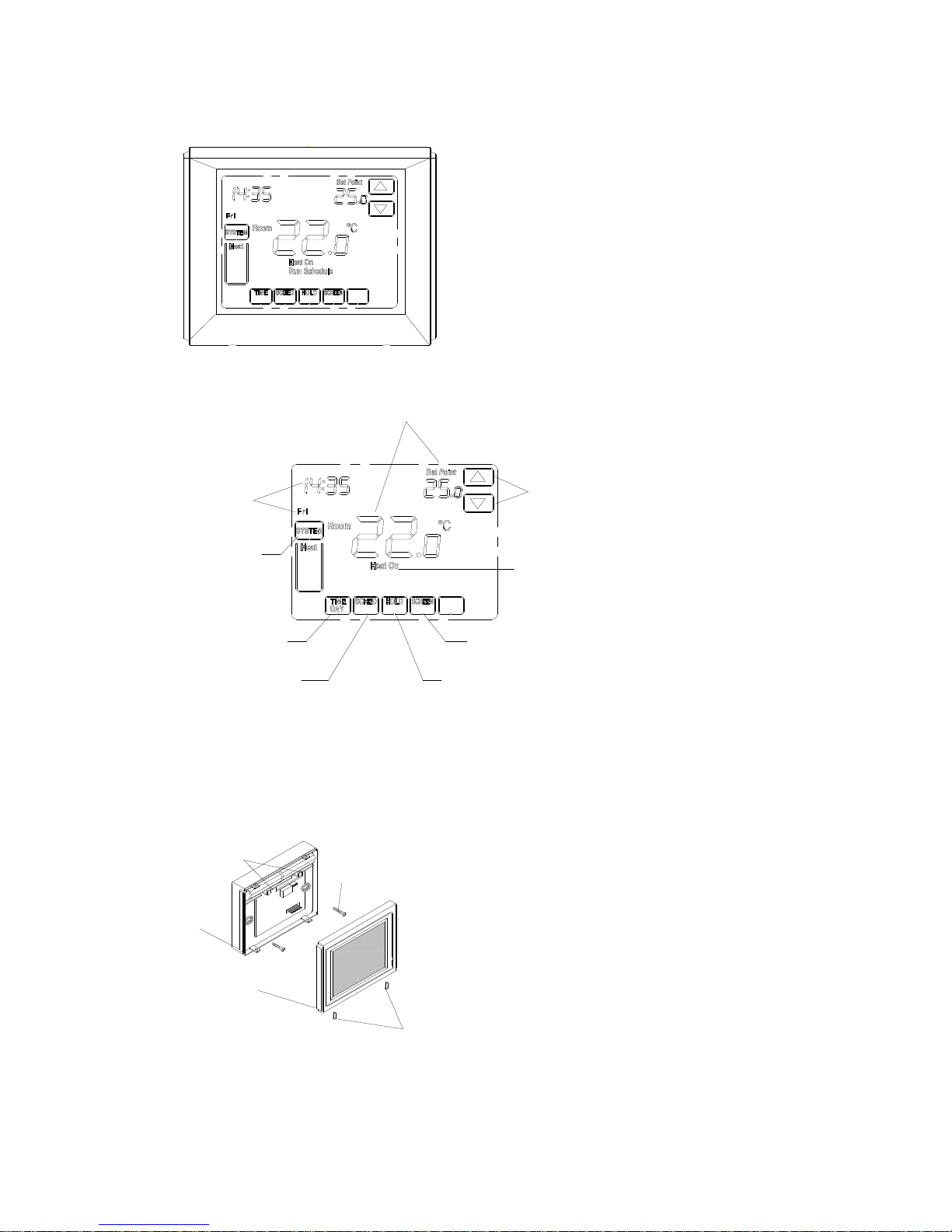
DG3000WHB-7B Touch Screen Thermostat
Home Screen Description
ATTACH THERMOSTAT BASE TO WALL
1. Remove 2 screws from the bottom of thermostat.
Gently pull the control panel straight off the base.
Forcing or prying on the thermostat will cause
damage to the unit.
2.
Install two fresh “AA” alkaline batteries in
battery compartment. Be sure to match
Time and Day
Room Temperature and Setting Temperature
Temperature Up/Down
TIME/DAY
Sets The Time
SCHED
Run Schedule or Set Schedule
HOLD
Sets a Permanent Hold and
Activates Vacation Hold
SCREEN
Locks Out The Screen To Allow For Cleaning
Shows When There Is a Call For Heating
SYSTEM
Selects Heat/Off
Figure 1
Figure 2
Figure 3
Fixing screw
Control panel
Base
Screw for mounting therm ostat to wall
Two AA batteries
Figure 1
Page 4

4
positive (+) ends of batteries with positive
(+) battery terminals in the battery
compartment.
3. Connect wires beneath terminal screws on power
supply module using appropriate wiring
schematic. See figure 4
4. Push power base into wall.
5. Using two mounting screws mount the power
base to the wall. Place a level against bottom of
base, adjust until level, and then tighten screws.
(Leveling is for appearance only and will not
affect thermostat operation.)
6. Replace control panel on the power base and fix
power base and control panel by removed two
screws in item 1
Page 5

5
WIRING DIAGRAM
1
2
3
230V AC
T2
T1
230V AC
3
2
1
250VA C
8A
8A 8A
8A
Pu mp or valve
Re lay
25 0V A C
8A
8A 8A
8A
Figure 4
CHECK THERMOSTAT OPERATION
The unit will be controlled via air sensor in the thermostat and the thermostat will determine
to activate/deactivate heating system by comparing set temperature with room temperature.
Press Up and Down key to adjust thermostat setting above room temperature 1℃ in fast heating
mode or 3℃ in slow heating mode, See configuration menu item 5. The heating should begin to
operate immediately
Configuration Menu
The configuration menu allows you to set certain thermostat operating characteristics to
your system or personal requirements.
1) Press system button till “Off” flash in the display.
2) Press DOWN to make the thermostat turn off.
3) Press CONF to enter into configuration mode.
4) The User Configuration menu is displayed in the up-right screen. Current setting is displayed
in the up-left screen.
Configuration Menu
Advance to Next Menu
Change The Current Setting
Current Setting
Press to Save
and Exit Confituration
Hold for 3 Seconds
to Revert to Factory
Default Setting
Page 6

6
5) Press DONE key to save the setting and exit configuration menu, Hold RESET key for 3
seconds display will flash 3 times and revert to factory default setting.
The configuration menu chart summarizes the configuration options. An explanation of each
option as follows:
Item Current Setting Menu Item Descriptions
1 -4 --- +4 CL (0) Select temperature display adjustment higher or
lower
2
20℃(68℉)—35℃(95℉)
AH(35℃)
Select maximum setting temperature for heating
3
5℃(41℉)—20℃(68℉)
AL(5℃)
Select minimum setting temperature limitation
4
℃/℉
FC(℃) Select temperature display to
℃
or
℉
5 FA/SL
HC(FA)
Select fast heating or slow heating
6 yES/nO PP(NO) Select pump protection YES
Cancel pump protection NO
7 24/12 7E (24) Selection of time scale
8 1/2/3 BL(1) Select display backlight mode
9 3/7 PS(7) Programming day in one week option
10 UnL/PAL/FUL LO(UnL) Select keypad Lockout function
1) Select temperature recalibrates Adjustment 4 LO to 4 HI –
You can adjust the room temperature display up to 4 higher or lower. Your thermostat was
accurately calibrated at the factory but you have the option to change the display temperature to
match your previous thermostat. The current or adjusted room temperature will be displayed on
the right side of the display.
2) Select maximum temperature set point
This feature provides a maximum set point temperature f. The default setting is 35℃ (95℉), It
can be changed between 20℃ (68℉) to 35℃ (95℉)
3) Select minimum temperature set point.
This feature provides a minimum set point temperature. The default setting is 5℃ (41℉), It
can be changed between 5℃ (41℉) to 20℃ (68℉)
4)
Select ℉℉℉℉ or ℃℃℃℃ readout
.
Changes the display readout to Centigrade or Fahrenheit as required
5) Select fast heating or slow heating
Page 7

7
Select FA to start heating immediately when the set point is 1℃ above the room temperature.
Select SL to start heating only when the set point is 3 ℃ above the room temperature.
6)
Select pump protection mode
For hot water installations, it is recommended to activate the pump at least 15 second every
24 hours in order to avoid any seizing. Select yES will activate pump protection mode. Select nO
will cancel the function.
7)
Selection of time scale
12 indicates 12 hour clock and 24 indicates 24 hour clock
8) Select display backlight mode
The display backlight improves display contrast in low lighting conditions. Select 1 the light
will be on when any button of the thermostat is touched. Select 2 the display will keep the light off.
Select 3 the display will keep the light on continuously. Factory default is 1.
9)
Programming day in one week option
There are 2 options for how to program the day in one week.
7: You can program in 7 individual days
3: You can program in 5 weekday and 1Saturday and 1Sunday.
10) Select
keypad
lockout on or off
UnL-unlock. All keys are available. Screen is unlocked
PAL-partially locked. All key functions are locked except SYSTEM key; temperature Up and
Down keys and the CANCEL key. Enter Configuration setup to unlock the screen
FUL-fully locked. Screen is fully locked except SYSTEM key. Enter Configuration setup to
unlock the screen
Operation Your Thermostat
Setting System Key
Heat-thermostat controls your heating system.
Off-Heating system is off
Setting Temperature Override
Your thermostat has three temperature override options: Hold Temperature Until, Permanent Hold and
Vacation Hold
Hold Temperature Until (Temporary Hold)
Holds temperature temporarily until next scheduled period time or until the time the user sets.
1) Press Up or Down arrow next to the temperature you want to adjust. “Hold Until” time
appears on the screen. The Hold Temperature until time defaults to the start time of the next
scheduled period.
2) Press Up or Down arrow next to the Time key to set desired time for the thermostat to
Page 8

8
resume schedule
3) Press the CANCEL or SCHED key to cancel “Hold Until” and resume schedule
Note: Once “Hold Until” time is reached, the thermostat shows “Run Schedule” on the screen to
indicate that temporary hold has ended.
Permanent Hold
Permanent Hold changes the temperature setting until permanent Hold is cancelled
1) Press HOLD key. “Permanent Hold” appears on the screen.
2) Press Up or Down arrow next to the temperature you want to set during “Hold’
3) Press CANCEL or SCHED key to cancel “Permanent Hold” and resume the schedule
Vacation Hold
Changes temperature setting for a designated number of days
1) Press the HOLD key. “Permanent Hold” appears on the screen.
Page 9

9
2) Press HOLD key again. Screen shows “Hold Until” one day
3) Press Up and Down arrow key next to the day to change the number of days you desire
thermostat to override the schedule
4) Press Up and Down arrow key next to the temperature to set the desired temperature while
away on holiday
5) To cancel the Vacation Hold override early, press the CANCEL or SCHED key.
Note: When the number of days of Vacation Hold expires, the screen shows Run Schedule to
indicate that Vacation Hold has ended.
Replacing Your Batteries
Low Batt warning flashes on the screen for approximately 30 days when your thermostat runs
out of batteries. Replace the batteries when Low batt warning flashes
Screen Locked
You can fully or partially lockout the keys on the touch screen interface. See Configuration
menu item 13 for information on turning these features on or off. If the thermostat shows
your thermostat screen is either fully or partially locked.
In partially locked mode, all key functions are locked except temperature SYSTEM key; Up
and Down keys and the CANCEL key. Users can temporarily change the set temperature
until next scheduled period reached. The next scheduled period start time shows on screen.
To cancel temperature override and begin following schedule, press CANCEL key. To unlock
screen, press SYSTEM key to Off and enter into the configuration menu to change the
keypad unlock.
In fully locked mode, only SYSTEM key is active and all of the other keys are locked. To
unlock screen, press SYSTEM key to Off and enter into the configuration menu to change the
keypad unlock.
Cleaning Your Thermostat Screen
The thermostat has a touch screen interaction. Follow these steps to clean the screen without
making thermostat changes:
1) Press the SCREEN key. Thermostat locks out all touch keys for 30 seconds to allow for
Page 10

10
cleaning.
2) Use damp cloth slightly moistened with water or house hold glass cleaner to clean the
screen
3) Repeat the above steps, as necessary
IMPORTANT
Do not spray any type of liquid directly on the thermostat itself. If using household glass
cleaner, spray cleaner on cloth. Then use a cloth to clean the thermostat screen
4) Press the DONE key to return to the Home Screen and normal operation.
Planning your program
Set Current Time and Day
1) Press TIME button once. The display will show the hour flashing
2) Press and hold either Up and Down key until you reach the correct hour
3) Press TIME once again. The display will show minutes flashing
4) Press and hold either Up and Down key until you reach the correct minutes
5) Press TIME once again. The display will show day of the week flashing
6) Press and hold either Up and Down key until you reach the correct day of the week
7) Press DONE to confirm setting and return to schedule running. Press CANCEL to cancel
setting and return to schedule running
Factory Pre-Program
Look at the factory preprogrammed times and temperatures shown in the sample schedule. If this
program will suit your needs, simply keep the thermostat in Run Schedule mode.
Wake Up
(Morning)
Leave For Work
(Day)
Return Home
(Evening)
Go To Bed
(Night)
Heating
Program
6:00 21℃ 8:00 17℃ 17:00 21℃ 22:00 17℃
Page 11

11
Planning Your Program
The Heating schedule below allow you to pencil in your own program times and temperatures.
The thermostat comes configured for 7 day programming and can also be configured for 5+1+1
programming
Factory setting are listed on Monday, Saturday and Sunday. If you are re-programming a 5+1+1
day schedule, pencil in your own times and temperatures directly below the factory times and
temperatures.
If you are re-programming a 7 day fill in all lines with the times and temperature you want.
Worksheet for Re-Programming 5+1+1 and 7 Day program
Heating
Program
Wake Up
(Morning)
Leave For Work
(Day)
Return Home
(Evening)
Go To Bed
(Night)
Mon
6:00 21℃ 8:00 17℃ 17:00 21℃ 22:00 17℃
Tue
Wed
Thu
Fri
Sat
6:00 21℃ 8:00 17℃ 17:00 21℃ 22:00 17℃
Sun
6:00 21℃ 8:00 17℃ 17:00 21℃ 22:00 17℃
Enter the Heating Program
Your thermostat can control up to four different schedule periods per day
Wake-Period when you awaken and want your home at a comfortable temperature
Leave-Period when you are away from home and want an energy-saving temperature
Return-Period when you return home and want your home back to a comfortable temperature
Sleep-Period when you are asleep and want an energy-saving temperature
1) Press SCHED key
2) Press DAY key to select the day of the week to be program. In 7 day programming mode, all
seven day can be selected. In 5+1+1 programming mode, only week day (Mon-Fri), Sat and
Sun can be selected.
Page 12

12
3) Press WAKE key. Once pressed, WAKE flashes to show it is selected
4) Press Up and Down keys to modify time and heat temperature from this screen.
5) Press LEAVE key and repeat step 4.
6) Press RETURN key and repeat 4
7) Press SLEEP key and repeat 5.
8) Press Day key and repeat 2)-7) to program another day of the week.
9) When complete, press DOWN key to return to run schedule. Hold RESET key for 3 seconds,
display will flash 3 times and back to factory default setting program.
Programming Tip: COPY Button
You may copy and daily program to another day or group of days by pressing the COPY button.
In 7 day programming mode when the COPY button is pressed, the other 6 days of the week will
flash. To copy the current program into the remaining six days, simply press the COPY button
again. To copy the current program to another day of the week, press DAY button to select the
day and press COPY to paste the program. In 5/1/1 day programming mode the copy function is
similar. The weekday (Mon-Fri) Program can be copied to Sat and Sun (both flashing) or use DAY
to choose Sat or Sun and press the COPY button to paste the program
 Loading...