

Page 1
Gas Cooker
CA 5140.2 GG
❏ This appliance is for use on liquid
propane/butane gas only
❏ The aeration adjustment for this appliance has
already been set
❏ In the interest of safety this appliance must be
installed and/or serviced by a competent person
as stated in the gas safety (installation and use)
(amendment) regulations 1990.
❏ Leave these instructions
with the user
Fitters and Users Instructions
GB
Page 2

2
CONTENTS
– Introduction ........................page 2
– Installation ..............................” 3-5
– Features and
Technical Data.....................” 6
– How to use the hob burners .” 7-8
– How to use the oven
and grill................................” 9-11
– Care and maintenance..........” 12-13
– Technical information .............” 14
– After sales service
and guarantee .....................” 15
INTRODUCTION
Congratulation on your purchase of this
CALOR GAS gas cooker which has
been carefully designed and produced
to give you many years of satisfactory
use.
Before using this appliance it is
essential that the following instructions
are carefully read and fully understood.
We would emphasize that the
installation section must be fully
complied with for both your safety and
to ensure that you obtain the maximum
benefits from your appliance.
INSTALLATION and CONNECTION TO
THE GAS SUPPLY
This appliance is supplied for use on
LIQUID PROPANE/BUTANE GAS only.
In the interests of safety this appliance
must be installed and serviced by a
competent person as stated in the Gas
Safety (Intallation and Use)
(Amendment) Regulations 1990.
Reference should also be made to the
IEE wiring regulations, the Building
Regulations, the Building Standards
(Scotland) Consolidated Regulations.
Detailed recommendations are
contained in the following British
Standard Codes of Practice: - BS6172,
BS5540 Pt 2, BS6891, all editions
being current.
IMPORTANT
This appliance should be fitted by a
Corgi registered fitter, in compliance
with regulation in force.
It is illegal to provide any assistance in
the installation of gas appliances
except to Corgi registered installers.
Any Corgi registered fitter requiring
help must provide name, address and
registration number.
Information supplied will be validated
before help is provided.
When the installation has been
completed, it is essential that a
thorough gas soudness test is carried
out. If a flexible connector is used,
ensure that the hose is free from kinks
and torsional stress and is not touching
the back of the cooker.
Introduction
Page 3

3
ELECTRICAL CONNECTION
WARNING! THIS APPLIANCE
MUST BE EARTHED.
This appliance must be connected by a
competent person, using fixed wiring
via a DOUBLE POLE SWITCHED
FUSED SPUR OUTLET.
We recommend that the appliance is
connected by a qualified electrician,
who is a member of the N.l.C.E l C.
and who will comply with the l.E.E. and
local regulations.
The wires in the mains lead are
coloured in accordance with the
following code:
Green & Yellow = Earth,
Blue = Neutral,
Brown = Live.
FUSE
DOUBLE POLE SWITCHED
FUSED SPUR OUTLET
USE A 3 AMP FUSE
ON
Fig. 1
As the colours of the wires in the
mains lead for the appliance, may not
correspond with the coloured markings
identifying the terminals in your spur
box, proceed as follows:
1) The wire which is coloured green
and yellow must be connected to
the terminal marked E (Earth)
or coloured Green.
2) The wire which is coloured blue
must be connected to the terminal
marked N (Neutral), or coloured
Black.
3) The wire which is coloured brown
must be connected to the terminal
marked L (Live), or coloured Red.
Installation
Page 4
4
PROVISION FOR VENTILATION
The room containing the cooker should
have an air supply in accordance with
BS.5540: Part 2: 1989.
All rooms require an openable window
or equivalent while some rooms require
a permanent vent in addition to the
openable window.
The cooker should not be installed in a
bed-sitting room, of volume less than
21 m
3
.
Where a DOMESTIC COOKER is
installed in a room or internal space,
that room or internal space shall be
MINIMUM PERMANENT OPENING FREE AREA FOR FLUELESS APPLIANCE
5 m3to
10 m
3
Openable
window or
equivalent also
required
Maximum
appliance
rated input
limit
Room volume
11 m3to
20 m
3
> 20 m
3
< 5 m
3
Type of appliance
Domestic oven, hot-
plate, grill or any
combination thereof.
None
50 (❊)
cm
2
Nil
cm
2
Nil
cm
2
100
cm
2
Yes
(❊) If the room or internal space containing these appliances has a door which opens
directly to outside, no permanent opening is required.
Installation
provided with a permanent opening
which communicates directly with
outside air and is sized in accordance
with table below. In domestic premises
the permanent opening shall be an air
vent.
If there are other fuel burning
appliances in the same room, BS.5540:
Part 2: 1989 should be consulted to
determine the requisite air vent
requirements.
If the cooker is installed in a cellar or
basement, it is advisable to provide an
air vent of effective area 100 cm
2
,
irrespective of the room volume.
Page 5
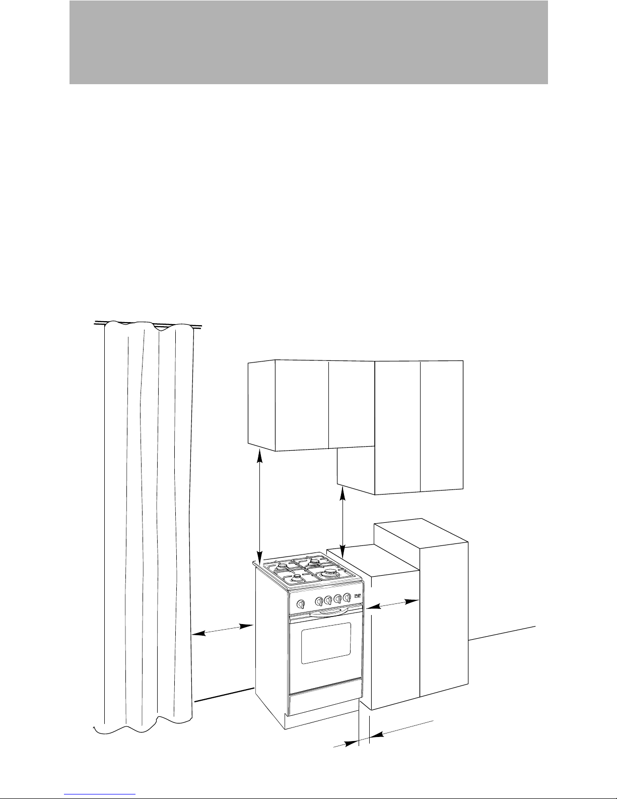
500 mm
800 mm
300 mm
19 mm
500 mm
5
LOCATION (fig. 2)
The cooker may be located in a
kitchen, a kitchen/diner or bed-sitting
room but not in a room containing a
bath or shower.
It is essential that the cooker is
positioned as stated below.
The cooker must be a minimum of 5
mm (1/5”) from the rear wall.
Shelves and wall cabinets must not be
fitted closer than 800 mm (32”) to the
hob burners.
Fig. 2
Installation
Curtains must not be fitted immediatly
behind appliance or within 500 mm
(20”) of the sides.
Base unit which are above the height
of the hotplate should be 300 mm (12”)
away.
It is advisable that the kitchen furniture
near the sides of the cooker is made
of heat resistant material, and the 19
mm (3/4”) air gap be maintained.
Page 6

6
900 mm
500 mm
500 mm
GAS BURNERS (Fig. 3)
1. Auxiliary burner (A)
1.00 kW
2. Semi-rapid burner (SR)
1.90 kW
3. Semi-rapid burner (SR)
1.90 kW
4. Rapid burner (R)
2.95 kW
GAS OVEN
– Gas burner - 3.25 kW
– Grill burner - 2.35 kW
– Usable oven volume
43 dm
3
CONTROL PANEL (Fig. 3)
5. Front right burner (4)
control knob
6. Rear right burner (3)
control knob
7. Rear left burner (2)
control knob
8. Front left burner (1)
control knob
9. Oven/Grill control knob
10. Oven light switch
11. Ignition push-button
9 8 7 6 5 10 11
2134
Fig. 3
Features and Technical Data
Page 7

7
The hob is made of steel coated with a
vitreous enamel to provide a durable
and attractive surface.
HOB BURNERS
Each hob burner is controlled by a
separate gas tap operated by a control
knob (fig. 4) which has 3 positions
marked on the bezel, these are:
– Symbol ● : tap closed (burner off)
– Symbol : High (maximum)
– Symbol : Low (minimum)
Push in and turn the knob anticlockwise to the selected position.
Low High
To turn the burner off, fully rotate the
knob clockwise to the off position: ●.
The maximum setting of the control tap
is for boiling, the minimum setting is for
slow cooking and simmering.
All working positions must be chosen
between the maximum and minimum
setting, never between the maximum
setting and the “OFF” position.
Fig. 4
LIGHTING OF HOB BURNERS
Push in and turn the appropriate
control knob in an anticlockwise
direction until the maximum position
(marked with the large flame symbol
) is reached.
Then press the ignition button
★ on
the front of the control panel.
After the burner lights, adjust the flame
to the setting you require.
How to use the Burners
Page 8

8
BURNERS POT DIAMETER
Auxiliary 16 cm
Semi-rapid 16 ÷ 22 cm
Rapid 22 ÷ 28 cm
Fig. 5
CHOICE OF BURNER
The burner must be chosen according
to the diameter of the pots and energy
required.
The hotplate has been designed with
safety in mind, however normal care in
use should be observed.
Do take care avoid burns and scalds
when reaching across the hotplate.
Pans with flat bases are more stable
than those which are warped.
Pans which are positioned centrally on
burners are more stable than those
which are offset.
It is far safer to position the pan
handles in such a way that they cannot
be accidentally knocked.
When deep fat frying fill the pan only
one third full of oil.
DO NOT cover the pan with a lid and
DO NOT leave the pan unattended.
In the unfortunate event of a fire, leave
the pan where it is and turn off all
controls.
Place a damp cloth or correct fitting lid
over the pan to smother the flames.
DO NOT use water on the fire.
Leave the pan to stand for at least 30
minutes or until cold.
How to use the Burners
Page 9

9
Fig. 6
THERMOSTAT GRADE TABLE
Knob mark Oven temperature
1 150 °C 300 °F
2 165 °C 330 °F
3 180 °C 355 °F
4 195 °C 385 °F
5 210 °C 410 °F
6 225 °C 440 °F
7 240 °C 465 °F
8 255 °C 490 °F
9 270 °C 520 °F
10 285 °C 545 °F
LIGHTING THE OVEN GAS BURNER
The thermostat allows the automatic
control of the temperature.
The gas delivery to the oven burner is
controlled by a two way thermostatic
tap (oven and grill burners) with flamefailure device.
To light the oven burner operate as
follow:
- Open the oven door and apply a
lighted mach or taper to hole “A” in
the oven base plate (fig. 6)
- Push and turn the oven knob anticlockwise to position 10.
- Once the oven burner is lit, wait for
about 15 seconds before releasing
the knob (time of priming of the
valve) and than close the oven door
slowly.
Turn the oven knob to the position
for the desired temperature (see the
thermostat grade table).
NEVER turn on the gas supply
before applying a lighted match or
taper to the hole “A”.
Ensure that the oven burner is alight
before closing the oven door.
THERMOSTAT
The thermostatic control tap knob is
marked with numbers from 1 to 10,
these correspond to the temperature
shown in the table, in addition the
“OFF” position is shown by the
symbol ●.
To choose the desired oven
temperature (check with the “Oven
cooking guide”, turn the control tap
knob until the number), required is
level with the line mark on the control
panel (facia).
How to use the Gas Oven
Fig. 7
A
Page 10

10
Fig. 8
LIGHTING THE GRILL BURNER
Do not grill with oven door closed.
Always fit the heat shield supplied
with the cooker under the front
panel before commencing operations
(Fig. 9).
WARNING. The heat shield and the
oven door reaches a very high
temperature whilst in use. Keep
children away and allow to cool
before removing.
The burner, heats a stainless steel net
which in-turn generates the infra-red
rays for grilling.
To light the grill burner operate as
follow:
- Open the oven door and apply a
lighted mach or taper to the both
sides of the grill burner (fig. 8)
- Push and turn the grill/oven knob
clockwise until you match the symbol
with the control panel reference
line.
- Once the grill burner is lit, wait for
about 15 seconds before releasing
the knob (time of priming of the
valve) and than set the oven door in
half-closed position.
NEVER turn on the gas supply
before applying a lighted match or
taper to the burner.
Partially close the oven door to the
grilling position.
Notes:
– The grill burner has only one setting,
that is full-on
– It is important that the heat shield is
fitted the correct way up, as shown
in the figure 9.
Fig. 9
How to use the Grill
Page 11

11
How to use the Oven
OVEN COOKING TEMPERATURES
MARK
APPROX. HEAT OF TYPE OF DISH TO COOK
TEMP. OVEN
1 150°C Very cool Meringue cakes,
(300°F) oven slow cooking items
1-2 150°C - 160°C Cool or Milk puddings, very rich fruit
(300°F - 320°F) slow oven cakes, i.e., Christmas
2 165°C Cool or Stews, casseroles, braising,
(300°F) slow oven rich fruit cakes, i.e., Dundee
2-3 170°C Warm oven Biscuits, rich plain cakes
(330°F) i.e., Madeira. Low temp. roasting
3 180°C Moderate Plain cakes, Victoria
(355°F) oven sandwich, raised meat pies
4 195°C Fairly hot Small cakes, savoury flans,
(380°F) oven fish
5 210°C Hot oven Plain cakes and buns, swiss rolls,
(410°F) fruit pies. High temp. roasting
6-7 225°C - 240°C Moderately Bread and bread rolls etc., scones,
(435°F - 465°F) hot oven flaky and rough puff pastry,
yorkshire pudding
8-9 255°C - 270°C Very hot Sausage rolls, mince pies, puff
(490°F - 520°F) oven pastry, pizza
10 285°C Very hot Browning ready cooked dishes
(545°F) oven
Page 12

12
CLEANING THE HOB:
Spillage on the hob can usually be
removed by a damp soapy cloth. More
obstinate stains can be removed by
rubbing gently with a soapy scouring
pad or mild household cleaner.
BURNERS
To be washed only with soapy water.
After each cleaning, make sure that the
burner-caps, as well as the burners,
have been well wiped off and
CORRECTLY POSITIONED.
It is essential to check the correct
position of the burner-caps as the least
displacement from the housing may
cause serious problems.
Fig. 10
CLEANING OVEN PARTS:
The oven interior and the chromium
plated shelves and runners can be
cleaned by damp soapy cloth.
Obstinate stains can be removed with
nylon scouring pads and gentle, nonabrasive, liquid cleaner. Provided the
oven is wiped over immediately after
roasting, only the minimum of cleaning
should be necessary.
TAPS
If a tap becomes stiff, do not force;
contact your local Service Centre.
(See enclosed Service Information)
FLEXIBLE TUBE
From time to time, check the flexible
tube connecting the gas supply to the
cooker.
It must be always in perfect condition;
in case of damage arrange for it to be
replaced by a Corgi registered fitter.
Care and Maintenance
Page 13

13
DOOR GLASS:
The glass of the oven door can be
cleaned with a soft, warm, soapy cloth,
then wiped clean with cold water and
polished with a soft clean cloth. Do not
use scouring pads or anything abrasive
on the oven door glass.
REMOVING THE OVEN DOOR:
To facilitate oven cleaning, it is possible
to remove the door.
Hinges “A” have two movable clips “B”
which can be connected to parts “C” of
the hinges when the door is completely
open in order to lock this in position.
Following this, the door can be lifted
upwards and removed.
To do this, lift on the sides of the door
near the hinges.
To remount the door, first insert the
hinges in their grooves. Now close the
door.
Do not forget to remove the two
movable clips “B” used to link to the
two hinges.
A
B
C
Fig. 11
Fig. 12
FITTING UP OF OVEN SHELVES
The oven shelves are provided with a
security block to prevent accidental
extraction.
They must be inserted operating as per
figure 12.
To pull them out operate in the reverse
order.
Care and Maintenance
Page 14

14
Description Nominal Reduced G 30/31
Power Power 28/37 mbar
By- Ø injector Ring opening Port.
[kW] [kW]
pass [1/100 mm] [mm] [g/h]
Auxiliary burner (A) 1.00 0.30 27 50 3 73
Semirapid burner (SR) 1.90 0.38 29 67 5,7 138
Rapid burner (R) 2.95 0.60 39 83 Fully open 214
Oven burner 3.25 0.85 45 - 47 86 Fully open 236
Grill burner 2.35 – – 78 Fully open 176
Cat: II 2H3+
Classe 1
Technical Information
Page 15

15
A guarantee card is supplied with this
cooker.
Your guarantee is offered as an extra
benefit and does not affect your legal
right.
In the event that you require After
Sales Service please contact your local
Service Centre as per the attached list.
For the conversion of the cooker, to
use a different gas, please contact your
local Service Centre (see enclosed
Service Information).
Components are guaranteed for a
period of 12 months from the date of
purchase, subject to the proviso that
the appliance has been:
1. Used solely for domestic purposes.
2. Used in accordance with this
instruction book.
3. Has not been subjected to misuse,
accident, or repaired or modified by
anyone not authorized to do so.
After Sales Service and Guarantee
Descriptions and illustrations in this booklet are given as simply indicative.
The manufacturer reserves the right, considering the characteristics of the models described
here, at any time and without notice, to make eventual necessary modifications for their
construction or for commercial needs.
Page 16

ß3
Ed. - Cod. 1101182
Distributed by: De' Longhi Limited
Bridle Close
Wellingborough NN8 4RJ
Manufactured by:
De' Longhi S.p.A.
31100 Treviso
Italy
 Loading...