

California Instruments MX60-3Pi, MX60-3Pi-MB, MX90-3, MX90-3Pi, MX90-3Pi-MB User Manual
...
Revision AJ
CompuMess Elektronik GmbH • Lise-Meitner-Str. 1 • D-85716 Unterschleißheim
Telefon (089) 32 15 01- 0 • Telefax (089) 3215 01-11 • www.compumess.de • www.netzteile.de
September 2008
by California Instruments.
All rights reserved.
Copyright 2002-2008
P/N 7003-960
MX Series
AC and DC Power Source
User Manual
Series I / Series II
TEL: +1 (858) 677-9040
FAX: +1 (858) 677-0940
Email:
Web Site:
sales@calinst.com
http://www.calinst.com

User Manual – Rev AJ California Instruments
User's Manual
AC Power Source
California Instruments, an AMETEK Company.
Models:
MX30-1
MX30-3
MX30-3Pi
MX45-1
MX45-3
MX45-3Pi
MX60-3
MX60-3Pi (-MB)
MX90-3
MX90-3Pi (-MB)
MX135-3
MX135-3Pi (-MB)
MX180-3
MX180-3Pi (-MB)
MX225-3
MX225-3Pi (-MB)
MX270-3
MX270-3Pi (-MB)
Note: For MX15-1, MX15-1Pi, see user manual P/N 7005-960.
Copyright 2002 - 2008, California Instruments. Rev AJ, September 2008.
2 MX Series

User Manual – Rev AJ California Instruments
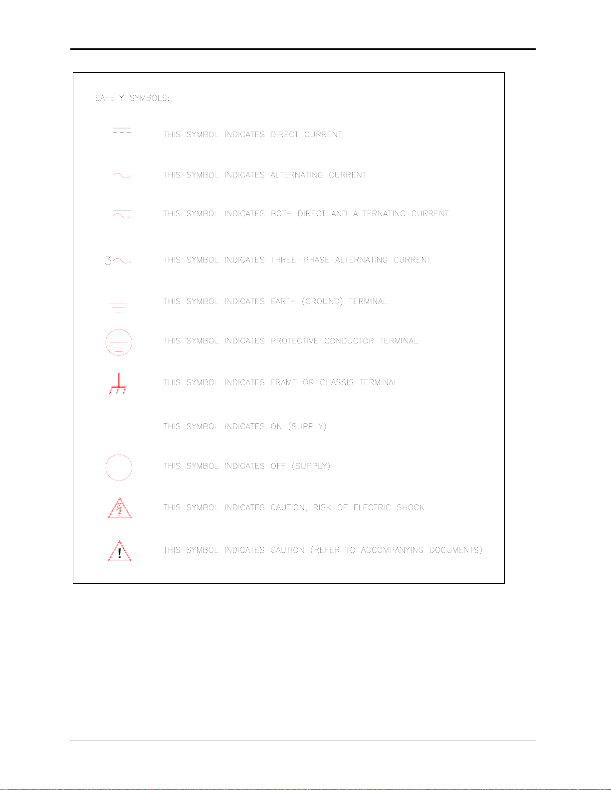
SAFETY SUMMARY
This power source contains high voltage and current circuits, which are potentially lethal.
Because of its size and weight, mechanical stability must be ensured. The following safety
guidelines must be followed when operating or servicing this equipment. These guidelines
are not a substitute for vigilance and common sense. California Instruments assumes no
liability for the customer’s failure to comply with these requirements. If the power source is
used in a manner not specified by California Instruments, the protection provided by the
equipment may be impaired.
BEFORE APPLYING POWER
1. Verify the correct three phase input voltage is applied to the unit. Input ratings are shown on the
model and serial number tag located at the rear of the unit.
2. The chassis and cabinet of this power source must be grounded to minimize shock hazard. A
chassis ground is provided at the input terminal block. This is located in the front of the cabinet
on the lower left hand side. The lower front cover panel must be removed to access the line
input and ground connections. The chassis ground must be connected to an electrical ground
through an insulated wire of sufficient gauge.
FUSES
Use only fuses of the specified current, voltage, and protection speed (slow blow, normal blow, fast
blow) rating. Do not short out the fuse holder or use a repaired fuse.
DO NOT OPERATE IN A VOLATILE ATMOSPHERE
Do not operate the power source in the presence of flammable gases or fumes.
DO NOT TOUCH ENERGIZED CIRCUITS
Disconnect the power cable before servicing this equipment. Even with the power cable
disconnected, high voltage can still exist on some circuits. Discharge these voltages before servicing.
Only qualified service personnel may remove covers, replace components or make adjustments.
DO NOT SERVICE ALONE
Do not remove covers, replace components, or make adjustments unless another person, who can
administer first aid, is present.
DO NOT EXCEED INPUT RATINGS
Do not exceed the rated input voltage or frequency. Additional hazards may be introduced because of
component failure or improper operation.
DO NOT MODIFY INSTRUMENT OR SUBSTITUTE PARTS
Do not modify this instrument or substitute any parts. Additional hazards may be introduced because
of component failure or improper operation.
MOVING THE POWER SOURCE
When moving the power source, observe the following:
1. Remove all AC power to unit.
2. Don not attempt to lift by hand. Raise the levelers and push the unit using two people to prevent
injury or use forklift equipment with a qualified operator.
ALLOW CAPACITORS TO DISCHARGE
Capacitors in the power source may hold a hazardous electrical charge even if the power source has
been disconnected from the mains supply. Allow capacitors to discharge to a safe voltage before
servicing internal circuits or touching exposed pins of mains supply connectors.
MX Series 3
User Manual – Rev AJ California Instruments
4 MX Series

User Manual – Rev AJ California Instruments
WARRANTY INFORMATION
CALIFORNIA INSTRUMENTS CORPORATION warrants each instrument manufactured by them to be free
from defects in material and workmanship for a period of one year from the date of shipment to the original
purchaser. Excepted from this warranty are fuses and batteries that carry the warranty of their original
manufacturer where applicable. CALIFORNIA INSTRUMENTS will service, replace, or adjust any defective
part or parts, free of charge, when the instrument is returned freight prepaid, and when examination reveals
that the fault has not occurred because of misuse, abnormal conditions of operation, user modification, or
attempted user repair. Equipment repaired beyond the effective date of warranty or when abnormal usage
has occurred will be charged at applicable rates. CALIFORNIA INSTRUMENTS will submit an estimate for
such charges before commencing repair, if so requested.
VOIDED WARRANTY
Any misuse or abuse of, as well as any modifications or changes made to any California Instruments
product will automatically void the factory warranty. Removing non-normal use related covers or any sealed
covers or lids also automatically voids factory warranty unless express written or email authorization is
obtained from the customer service department in advance. The customer service department can be
reached via email at
support@calinst.com.
SERVICE PROCEDURE
If a fault develops, notify CALIFORNIA INSTRUMENTS at support@calinst.com or its local representative,
giving full details of the difficulty, including the model number and serial number. On receipt of this
information, service information or a Return Material Authorization (RMA) number will be given. Add the
RMA number furnished to the shipping label. Pack the instrument carefully to prevent transportation
damage, affix label to shipping container, and ship freight prepaid to the factory. CALIFORNIA
INSTRUMENTS shall not be responsible for repair of damage due to improper handling or packing.
Instruments returned without RMA No. or freight collect may be refused at California Instruments discretion.
Instruments repaired under Warranty will be returned either via prepaid surface freight or low cost airfreight
at California Instruments discretion. Instruments repaired outside the Warranty period will be returned
freight collect, Ex Works CALIFORNIA INSTRUMENTS 9689 Towne Centre Drive, San Diego, CA 92121-
1964. If requested, an estimate of repair charges will be made before work begins on repairs not covered
by the Warranty.
DAMAGE IN TRANSIT
The instrument should be tested when it is received. If it fails to operate properly, or is damaged in any
way, a claim should be filed immediately with the carrier. The claim agent should obtain a full report of the
damage, and a copy of this report should be forwarded to us by fax or email (Fax: 858 677 0940, Email:
support@calinst.com). CALIFORNIA INSTRUMENTS will prepare an estimate of repair cost and repair the
instrument when authorized by the claim agent. Please include model number and serial number when
referring to the instrument.
SPARE PARTS
To order spare parts, user manuals, or determine the correct replacement part for your California
Instruments products, please contact the Customer Service department by phone at + 1 858 677 9040,
press 2 or by email
support@calinst.com.
MX Series 5

User Manual – Rev AJ California Instruments
Table of Contents
1. Introduction................................................................................................................................... 11
1.1 General Description......................................................................................................................... 11
1.2 Manual organization and format ...................................................................................................... 11
1.3 Different Model Series..................................................................................................................... 12
2. Specifications ............................................................................................................................... 13
2.1 Electrical.......................................................................................................................................... 13
2.2 Mechanical ...................................................................................................................................... 22
2.3 Environmental ................................................................................................................................. 23
2.4 Regulatory....................................................................................................................................... 23
2.5 Front Panel Controls ....................................................................................................................... 23
2.6 Special Features and Options ......................................................................................................... 24
2.7 Supplemental Specifications ........................................................................................................... 31
3. Unpacking and Installation ........................................................................................................... 36
3.1 Unpacking ....................................................................................................................................... 36
3.2 Power Requirements....................................................................................................................... 36
3.3 Mechanical Installation .................................................................................................................... 37
3.4 AC Input Connections and Wiring ................................................................................................... 37
3.5 AC On/Off Circuit Breaker on MX Series front panel....................................................................... 40
3.6 Output Connections......................................................................................................................... 42
3.7 Connectors - Rear Panel................................................................................................................. 55
3.8 Multiple Cabinet System Configurations (incl. –MB)........................................................................ 63
3.9 Multiple Cabinet Power Up/Down Procedures................................................................................. 65
3.10 Clock and Lock Configurations........................................................................................................ 66
3.11 Basic Initial Functional Test............................................................................................................. 68
3.12 Remote Inhibit / Remote Shutdown................................................................................................. 70
3.13 Junction Box Accessory .................................................................................................................. 71
3.14 Output Filter Box Accessory............................................................................................................ 72
3.15 Fuse Box Accessory........................................................................................................................ 73
4. Front Panel Operation .................................................................................................................. 74
4.1 Tour of the Front Panel ................................................................................................................... 74
4.2 Menu Structure................................................................................................................................81
4.3 Output Programming ..................................................................................................................... 119
4.4 Waveform Management [3Pi Controller only]................................................................................ 121
4.5 Standard Measurements ............................................................................................................... 126
4.6 Advanced Measurements [3Pi Controller only].............................................................................. 128
4.7 Transient Programming................................................................................................................. 137
5. Principle of Operation ................................................................................................................. 144
5.1 General ......................................................................................................................................... 144
5.2 Overall Description ........................................................................................................................ 144
5.3 Controller Assembly ...................................................................................................................... 146
5.4 System Interface Board................................................................................................................. 150
5.5 Current / Voltage Sensor Board .................................................................................................... 150
5.6 Low Voltage Power Supply............................................................................................................ 150
5.7 Power Module ............................................................................................................................... 151
6. Calibration................................................................................................................................... 156
6.1 Recommended Calibration Equipment.......................................................................................... 156
6.2 Front Panel Calibration Screens.................................................................................................... 157
6.3 Routine Measurement Calibration ................................................................................................. 160
6.4 Routine Output Calibration ............................................................................................................ 164
6.5 Non-Routine Calibration ................................................................................................................ 171
6 MX Series

User Manual – Rev AJ California Instruments
7. Service ........................................................................................................................................ 176
7.1 Cleaning.........................................................................................................................................176
7.2 General..........................................................................................................................................176
7.3 Basic operation ..............................................................................................................................176
7.4 Advanced Troubleshooting. ...........................................................................................................178
7.5 Factory Assistance ........................................................................................................................180
7.6 Fuses.............................................................................................................................................181
7.7 Firmware Updates .........................................................................................................................182
8. Top Assembly Replaceable Parts .............................................................................................. 185
9. Options........................................................................................................................................ 189
9.1 Introduction....................................................................................................................................189
9.2 Option -HV: Additional AC Voltage Range..................................................................................... 190
9.3 Option –160: RTCA/DO-160 Tests ................................................................................................191
9.4 Option –411: IEC 61000-4-11 Voltage Dips and Interruptions ....................................................... 205
9.5 Option –413: IEC 61000-4-13 Interharmonics Test .......................................................................213
9.6 Option –704: MilStd704 Tests........................................................................................................224
9.7 Option –ABD: Airbus ABD0100.1.8 Test .......................................................................................236
9.8 Option –AMD: Airbus AMD24C Test.............................................................................................. 236
9.9 Option –787: Boeing B787-0147 Test........................................................................................... 236
9.10 Option –WHM: Watt Hour Measurement .......................................................................................237
10. Error Messages .......................................................................................................................... 239
Index.................................................................................................................................................. 244
MX Series 7

User Manual – Rev AJ California Instruments
List of Figures
Figure 2-1: MX30-3 Voltage / Current Rating Chart for 150/300 V AC Ranges......................................................................... 16
Figure 2-2: MX45-3 Voltage / Current Rating Chart for 150/300 V AC Ranges – Max Rating.................................................... 17
Figure 2-3: Voltage / Current Rating Chart for 150/300 V AC Ranges – Derated....................................................................... 17
Figure 2-4: MX30-3 Voltage / Current Rating Chart for 200/400 V DC Ranges.......................................................................... 18
Figure 2-5: MX45-3 Voltage / Current Rating Chart for 200/400 V DC Ranges – Max. Rating ..................................................18
Figure 2-7: MX30-3 Voltage / Current Rating Chart, -HV Option............................................................................................... 27
Figure 2-8: MX45-3 Voltage / Current Rating Chart, -HV Option – Max. Rating......................................................................... 27
Figure 2-9: Voltage / Current Rating Chart, -HV Option – Derated............................................................................................. 27
Figure 2-10: -HF Option Voltage Frequency Rating 300V range................................................................................................ 29
Figure 2-11: -HF Option Voltage Frequency Rating 150V range................................................................................................ 29
Figure 2-12: MX output filter option schematic ...........................................................................................................................33
Figure 2-13: MX45 Output Noise 10 KHz – 1 MHz ..................................................................................................................... 34
Figure 2-14: MX45 Output Noise 10 KHz - 1 MHz with optional Filter........................................................................................35
Figure 3-1: The MX45 Power Source..........................................................................................................................................36
Figure 3-2: Location of AC Input Fuse Block and Chassis Ground Connection - Front View, Access Panel Removed............ 38
Figure 3-3: MX Series AC Input Connection Diagram (Rear view).............................................................................................39
Figure 3-4: Rear Panel................................................................................................................................................................ 41
Figure 3-5: External sense cable shield connection to chassis ground ...................................................................................... 42
Figure 3-6: Location of Output Terminals (Front view)................................................................................................................44
Figure 3-7: MX30-1 / MX45-1 Output Wiring (Rear view) ........................................................................................................... 45
Figure 3-8: MX30-3 / MX45-3 Output Wiring (Rear view) ........................................................................................................... 46
Figure 3-9:MX60, MX60-MB, MX90 or MX90-MB Output Wiring (Rear view) ............................................................................47
Figure 3-10: Two MX's in Clock and Lock mode Output Wiring (Rear view) .............................................................................. 48
Figure 3-11: MX135 or MX135-MB Output Wiring (Rear view)................................................................................................... 50
Figure 3-12: Three MX's in Clock and Lock mode - Output Wiring (Rear view) .........................................................................51
Figure 3-13: MX180, MX225 or MX270 Output Wiring (Rear view)...........................................................................................53
Figure 3-14: Ship kit Terminal Block dimensions........................................................................................................................ 54
Figure 3-15: RS232C Cable for PC Connection wiring diagram – MX without USB................................................................... 59
Figure 3-16: USB Connector pin orientation. .............................................................................................................................. 60
Figure 3-17: Emergency Switch (ES Option) shut off inter connect on -MB systems.................................................................62
Figure 3-18: Multi-Cabinet DIP Switch Location and Setting ...................................................................................................... 64
Figure 3-19: Functional Test Setup............................................................................................................................................. 69
Figure 3-20: 7003-416-1 Output Junction Box............................................................................................................................71
Figure 3-21: 7003-424-1 Output noise filter box. ........................................................................................................................72
Figure 3-22: 7003-426-1 Output Fuse Box .................................................................................................................................73
Figure 4-1: Shuttle Knob ............................................................................................................................................................. 76
Figure 4-2: FUNCTION Keypad.................................................................................................................................................77
Figure 4-3: Entering Values from the Decimal Keypad...............................................................................................................79
Figure 4-4: Cursor UP Key Movement........................................................................................................................................79
Figure 4-5: Cursor DOWN key Movement .................................................................................................................................. 80
Figure 4-6: Main Menu 1 Screen ................................................................................................................................................80
Figure 4-7: Menu 1 through 3......................................................................................................................................................81
Figure 4-8: PROGRAM Menu ..................................................................................................................................................... 85
Figure 4-9: MEASUREMENTS Screen, Single Phase and Three Phase Modes .......................................................................87
Figure 4-10: HARMONICS/TRACE ANALYSIS Screen..............................................................................................................89
Figure 4-11: TRANSIENTS Menu...............................................................................................................................................92
Figure 4-12: VOLTAGE SURGE/SAG SETUP Screen...............................................................................................................93
Figure 4-13: VOLTAGE SWEEP/STEP SETUP Screen.............................................................................................................95
Figure 4-14: FREQUENCY SWEEP/STEP SETUP Screen .......................................................................................................97
Figure 4-15 VOLTAGE/FREQUENCY SWEEP/STEP SETUP Screen .....................................................................................98
Figure 4-16:START/VIEW TRANSIENT SEQUENCE Screen.................................................................................................... 99
Figure 4-17: WAVEFORMS Menu ............................................................................................................................................ 100
Figure 4-18: APPLICATIONS Menu..........................................................................................................................................103
Figure 4-19: SETUP REGISTERS Menu..................................................................................................................................104
Figure 4-20: UTILITY Menu ......................................................................................................................................................105
Figure 4-21: GPIB/RS232 SETUP Menu .................................................................................................................................. 108
Figure 4-22: VOLTAGE/CURRENT CONTROL SETUP Menu................................................................................................. 109
Figure 4-23: INITIAL SETUP Menus......................................................................................................................................... 111
Figure 4-24: LIMIT SETUP Menu..............................................................................................................................................113
Figure 4-25: CONFIGURATION SETUP Menus....................................................................................................................... 114
Figure 4-26: OUTPUT IMPEDANCE Menu............................................................................................................................... 116
Figure 4-27: MEASUREMENT CAL FACTORS Menu (Series I only) ......................................................................................117
Figure 4-28: MEASUREMENT CAL FACTORS Menu (Series II only) .....................................................................................117
Figure 4-29: OUTPUT CAL FACTORS Menu (Series I only).................................................................................................... 118
Figure 4-30: OUTPUT CAL FACTORS Menu (Series II only)................................................................................................... 118
Figure 4-31: Selecting a Waveform ..........................................................................................................................................121
Figure 4-32: Selecting Waveforms for Single Phase or All Phases .......................................................................................... 121
8 MX Series

User Manual – Rev AJ California Instruments
Figure 4-33: Custom Waveform Creation with GUI Program ....................................................................................................122
Figure 4-34: Waveform Crest Factor Affects Max. rms Voltage................................................................................................124
Figure 4-35: Waveform Frequency Domain View Mode ...........................................................................................................125
Figure 4-36: Scrolling Through Tabular FFT Data ....................................................................................................................129
Figure 4-37: Scrolling through bar chart FFT Data....................................................................................................................129
Figure 4-38: Scrolling Through Acquired Waveform Data.........................................................................................................131
Figure 4-39: SET VOLT Trigger Source Acquisition .................................................................................................................133
Figure 4-40: Positive Trigger Delay (Post Trigger Data) ...........................................................................................................135
Figure 4-41: Negative Trigger Delay (Pre-Trigger Data) ...........................................................................................................136
Figure 4-42: Pulse Transients ...................................................................................................................................................138
Figure 4-43: List Transients.......................................................................................................................................................139
Figure 4-44: Switching Waveforms in a Transient List..............................................................................................................142
Figure 4-45: START/VIEW TRANSIENT SEQUENCE Menu ...................................................................................................143
Figure 5-1: MX Series Functional Block Diagram .....................................................................................................................144
Figure 5-2: MX Series Detailed Block Diagram.........................................................................................................................148
Figure 5-3: Power Module Detailed Block Diagram ..................................................................................................................149
Figure 5-4: Power Module Layout .............................................................................................................................................151
Figure 5-5: Amplifier Board Layout............................................................................................................................................153
Figure 6-1: Calibration Setup MX45-1 (Rear view) ...................................................................................................................158
Figure 6-2: Calibration Setup MX30-3Pi, MX45-3Pi or MX30-3, MX45-3 (Rear view)..............................................................159
Figure 6-3: Current Measurement Calibration Setup (Rear view) .............................................................................................160
Figure 6-4: DC offset AC filter ...................................................................................................................................................164
Figure 6-5: -413 Option Aux Generator Adjustments ................................................................................................................169
Figure 9-1: Application Menu ....................................................................................................................................................192
Figure 9-2: DO160 Main Menu..................................................................................................................................................193
Figure 9-3: Normal State...........................................................................................................................................................193
Figure 9-4: Voltage Modulation .................................................................................................................................................195
Figure 9-5: Frequency Modulation ............................................................................................................................................196
Figure 9-6: Power Interrupt .......................................................................................................................................................197
Figure 9-7: Power Interrupt for Group 2 and 3 ..........................................................................................................................198
Figure 9-8: Emergency Screen .................................................................................................................................................199
Figure 9-9: Abnormal Screen ....................................................................................................................................................200
Figure 9-10: DO-160 DC Main Menu ........................................................................................................................................202
Figure 9-11: Normal State.........................................................................................................................................................202
Figure 9-12: Abnormal State .....................................................................................................................................................203
Figure 9-13: Application Menu ..................................................................................................................................................207
Figure 9-14: IEC1000-4-11 Menu..............................................................................................................................................207
Figure 9-15: IEC Dips and Interrupts.........................................................................................................................................208
Figure 9-16: Voltage Variation Screen ......................................................................................................................................210
Figure 9-17: EN 61000-4-11 Voltage Variation specification- Edition 1.0 .................................................................................211
Figure 9-18: EN 61000-4-11 Voltage Variation specification- Edition 2.0 .................................................................................211
Figure 9-19: IEC 61000-4-11 GUI screen. ................................................................................................................................212
Figure 9-20: Application Setup Menus ......................................................................................................................................214
Figure 9-21: IEC1000-4-13 Menu..............................................................................................................................................214
Figure 9-22: IEC 1000-4-13 FCURVE.......................................................................................................................................216
Figure 9-23: IEC 1000-4-13 OSWING.......................................................................................................................................216
Figure 9-24: IEC 1000-4-13 SWEEP.........................................................................................................................................217
Figure 9-25: IEC 1000-4-13 Harmonics ....................................................................................................................................217
Figure 9-26: IEC 1000-4-13 INTERHARMONICS.....................................................................................................................218
Figure 9-27: IEC 61000-4-13 Meister Curve .............................................................................................................................218
Figure 9-28: IEC 61000-4-13 Test Flowchart Class 1 and 2.....................................................................................................220
Figure 9-29:IEC 61000-4-13 Test Flowchart Class 3................................................................................................................221
Figure 9-30: MENU 2 SCREEN ................................................................................................................................................223
Figure 9-31: INTERHARMONICS SCREEN .............................................................................................................................223
Figure 9-32: Application Menu ..................................................................................................................................................226
Figure 9-33: MIL704 Menu........................................................................................................................................................227
Figure 9-34: Steady State Menu ...............................................................................................................................................227
Figure 9-35: Transient Menu.....................................................................................................................................................229
Figure 9-36: Emergency Menu..................................................................................................................................................230
Figure 9-37: Abnormal Screen ..................................................................................................................................................231
Figure 9-38: MIL704 DC Menu..................................................................................................................................................232
Figure 9-39: Steady State DC ...................................................................................................................................................232
Figure 9-40: Transient Menu.....................................................................................................................................................233
Figure 9-41: Abnormal Test Screen ..........................................................................................................................................234
Figure 9-42: Emergency Test....................................................................................................................................................235
Figure 9-43: Application Screen................................................................................................................................................237
Figure 9-44: Watt-Hour Meter Screen .......................................................................................................................................237
Figure 9-45: WH-Meter Screen with Function Active ................................................................................................................237
MX Series 9

User Manual – Rev AJ California Instruments
List of Tables
Table 3-1: Suggested Input Wiring Sizes for each MX Cabinet * ...............................................................................................40
Table 3-2: Suggested Output Wiring Sizes * ..............................................................................................................................43
Table 3-3: Output Terminal connections.....................................................................................................................................44
Table 3-4: System Interface Connectors.....................................................................................................................................56
Table 3-5: Analog Interface Connector ....................................................................................................................................... 56
Table 3-6: BNC Connectors........................................................................................................................................................57
Table 3-7: BNC Connectors........................................................................................................................................................57
Table 3-8: External Sense Connector.........................................................................................................................................57
Table 3-9: RS232 Connector pin out – MX with RS232 and USB. .............................................................................................58
Table 3-10: RS232C Connector pin out – MX with RS232 but no USB...................................................................................... 58
Table 3-11: USB Connector pin out. ........................................................................................................................................... 60
Table 3-12: RJ45 LAN Connector pin out. .................................................................................................................................. 61
Table 3-13: Clock and Lock Configuration settings ....................................................................................................................66
Table 3-14: Clock and Lock Initialization settings....................................................................................................................... 67
Table 3-15: Remote Inhibit Mode Settings.................................................................................................................................. 70
Table 6-1: Calibration Load Values........................................................................................................................................... 161
Table 6-2: Measurement Calibration Table............................................................................................................................... 163
Table 6-3: Output Calibration Table – MX Series I ...................................................................................................................170
Table 6-4: Output Calibration Table – MX Series II ..................................................................................................................170
Table 6-5: Current Limit Calibration .......................................................................................................................................... 173
Table 6-6: Programmable Z adjustment pots............................................................................................................................ 175
Table 6-7: Formulas to calculate R and L ................................................................................................................................. 175
Table 7-1: Basic Symptoms ...................................................................................................................................................... 176
Table 7-2: MX Fuse Ratings .....................................................................................................................................................181
Table 7-3: Flash Down load Messages..................................................................................................................................... 184
Table 8-1: Replaceable Parts ...................................................................................................................................................187
Table 8-2: Fuses ....................................................................................................................................................................... 188
Table 9-1: Normal Voltage and Frequency Minimum...............................................................................................................194
Table 9-2: Normal Voltage and Frequency Maximum...............................................................................................................194
Table 9-3: Normal Voltage Unbalance......................................................................................................................................194
Table 9-4: Normal VoltageSurge Sequence .............................................................................................................................198
Table 9-5: Normal Frequency Transient Sequence .................................................................................................................. 199
Table 9-6: Normal Frequency Variation Sequence...................................................................................................................199
Table 9-7: Emergency Voltage and Frequency Minimum.........................................................................................................200
Table 9-8: Emergency Voltage and Frequency Maximum........................................................................................................200
Table 9-9: Emergency Voltage Unbalance ............................................................................................................................... 200
Table 9-10: Abnormal Voltage Minimum................................................................................................................................... 201
Table 9-11: Abnormal Voltage Maximum.................................................................................................................................. 201
Table 9-12: Abnormal Frequency Transient..............................................................................................................................201
Table 9-13: Normal Voltage Minimum ......................................................................................................................................202
Table 9-14: Normal Voltage Maximum .....................................................................................................................................203
Table 9-15: Voltage Surge ........................................................................................................................................................ 203
Table 9-16: Abnormal Voltage Surge........................................................................................................................................ 204
Table 9-17: Phase mapping......................................................................................................................................................206
Table 9-18: IEC 61000-3-34 Table C.2.....................................................................................................................................206
Table 9-19: Dips and Interruptions Tests Performed During RUN ALL ...................................................................................208
Table 9-20: Voltage Variations Test Performed During RUN ALL ............................................................................................ 210
Table 10-1: Error Messages .....................................................................................................................................................243
10 MX Series

User Manual – Rev AJ California Instruments
1. Introduction
This instruction manual contains information on the installation, operation, calibration and
maintenance of all power systems that use the MX Series power sources with the
programmable controller.
1.1 General Description
The MX Series AC and DC power source systems are high efficiency, floor standing AC and DC
power sources that provide a precise output with low distortion. Available voltage ranges are
150 Vac, 300 Vac and 400 Vac in AC mode and 200 Vdc and 400 Vdc in DC mode. The MX303Pi and MX45-3Pi can operate in either single or three-phase mode. The MX30 and MX45 is
also available in just single or three-phase mode. All other models always operate in threephase mode.
Models with a -1 or -3 designation provide full front panel operation but do not include certain
features such as arbitrary waveform generation unless added as an option at the time of order.
Models with the Pi controller offer several additional standard features, including the RS232C,
USB, LAN (option) and IEEE-488 interfaces, arbitrary waveform generation, dual voltage ranges
and additional measurement functions.
The MX Series units are contained in a compact floor standing enclosure on casters. This allows
the units to be moved around more easily.
Read the installation instructions carefully before attempting to install and operate the MX Series
power systems.
1.2 Manual organization and format
All user documentation for California Instruments power sources is provided on CDROM in
electronic format. (Adobe Portable Document Format) The required Adobe PDF viewer is
supplied on the same CDROM. This manual may be printed for personal use if a hardcopy is
desired. To request a hardcopy from California Instruments, contact customer service at
support@calinst.com. There will be an additional charge for printed manuals.
This manual contains sections on installation, normal use, maintenance and calibration. If the
MX system is equipped with a GPIB, RS232C, USB or LAN interface, refer to the MX
Programming manual for information on using the remote control interfaces and command
syntax. The programming manual is provided on the same CDROM as this user manual.
MX Series 11

User Manual – Rev AJ California Instruments
1.3 Different Model Series
There are two versions of the MX Series product, Series I and Series II. This user manual
covers both MX model series with top level assembly part numbers 7003-400 (Series I) and
7003-422 (Series II). The difference between the Series I and the Series II is the controller used.
The Series II uses a newer controller design but retains backward compatibility with the Series I
products. The part number is shown on the model / serial number tag on the back of the MX
series. All Series II will have a firmware revision of 4.0 or higher. The firmware revision is
displayed briefly at power up on the LCD display and can also be queried over the bus by using
the *IDN? command.
Differences between the two model series are restricted to:
Reduced number of measurement calibration coefficients on Series II.
Increased measurement sampling rate on Series II.
Maximum DC offset range in AC+DC mode is 250Vdc on Series I, 220Vdc on Series II
Where relevant, differences are highlighted throughout the user manual.
12 MX Series
User Manual – Rev AJ California Instruments
2. Specifications
Specifications shown are valid over an ambient temperature range of 25 5 C and apply after a
30 minute warm-up time. Unless otherwise noted, all specifications are per phase for sine wave
output into a resistive load. For three phase configurations or mode of operation, all
specifications are for Line to Neutral (L-N) and phase angle specifications are valid under
balanced load conditions only.
Note: Specifications for input and output current and power on MX180, MX225 and MX270
configurations are 4, 5 and 6 times those of MX45-3 and are not separately listed.
2.1 Electrical
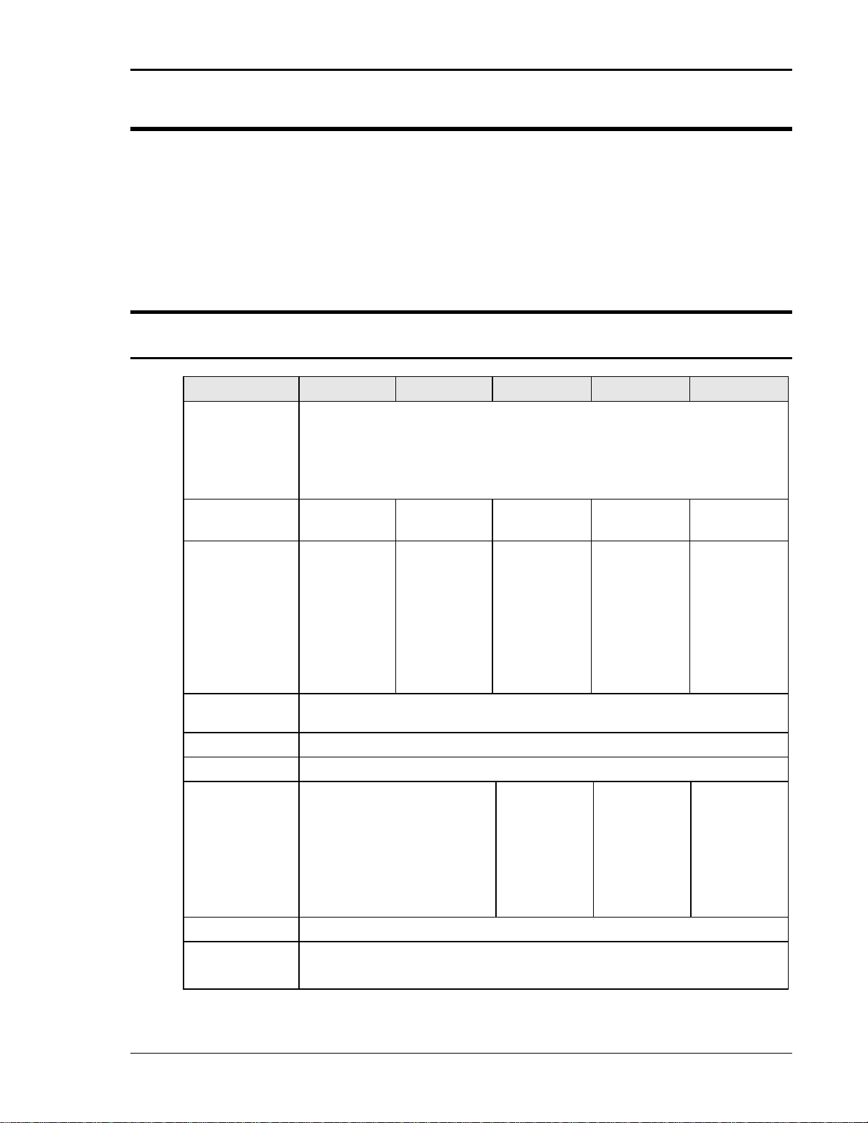
2.1.1 Input
Parameter MX30 MX45 MX60 MX90 MX135
Line Voltage:
(3 phase, 3
wire + ground
(PE))
208 V
230 V
400 V
480 V
10%
LL
10%
LL
10%
LL
10%
LL
Line VA: 37 KVA 53 KVA 74 KVA 106 KVA 159 KVA
Line Current: 116 A
187 V
105 A
207 V
60 A
360 V
50 A
432 V
Line
47-63 Hz
RMS
RMS
RMS
RMS
@
LL
@
LL
@
LL
@
LL
175 A
187 V
157 A
207 V
90 A
360 V
75 A
432 V
RMS
RMS
RMS
RMS
@
LL
@
LL
@
LL
@
LL
Each MX30
chassis
requires its
own AC
service.
Total Line
currents are
2 x MX30
Each MX45
chassis
requires its
own AC
service.
Total Line
currents are
2 x MX45
Each MX45
chassis
requires its
own AC
service.
Total Line
currents are
3 x MX45
Frequency:
Efficiency: 85 % (typical) depending on line and load
Power Factor: 0.95 (typical) / 0.99 at full power.
Inrush Current: 230 Apk @ 208 V
220Apk @ 230 V
132Apk @ 400 V
110Apk @ 480 V
LL
LL
LL
LL
Each MX30
chassis
requires its
own AC
service.
Total Peak
currents are
2 x MX30
Each MX45
chassis
requires its
own AC
service.
Total Peak
currents are
2 x MX45
Each MX45
chassis
requires its
own AC
service.
Total Peak
currents are
3 x MX45
Hold-Up Time: > 10 ms
Isolation
Voltage:
2200 VAC input to output
1350 VAC input to chassis
MX Series 13
User Manual – Rev AJ California Instruments
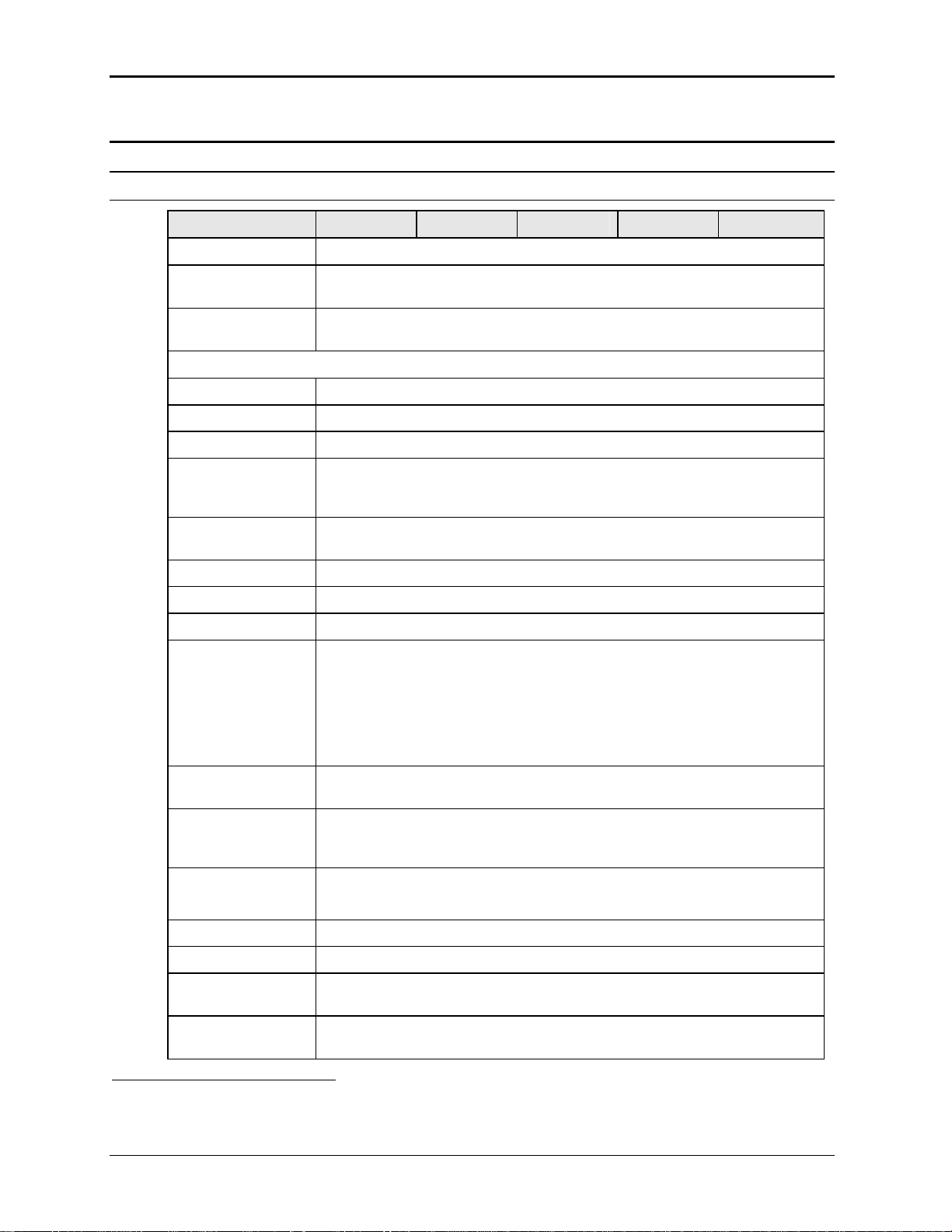
2.1.2 Output
Note: All specifications are for AC and DC unless otherwise indicated.
Output Parameter MX30 MX45 MX60 MX90 MX135
Modes
Std
AC, DC
Controller
Pi
AC, DC, AC+DC
Controller
Voltage:
Ranges (L-N):
AC Mode Low: 0 - 150 V / High: 0 - 300 V
DC Mode Low: 0 - 200 V / High: 0 - 400 V
AC+DC Mode AC: Low: 0 - 150 V / High: 0 - 300 V
DC Offset: Low Vrange: 0 - 150 V
High Vrange: 0 - 220 V (Series II) / High; 0 – 250 V (Series I).
Note:
On MX units with standard controller, only one voltage range is available unless
the -R range change option is installed.
Resolution:
AC Mode 0.1 V
DC Mode 0.1 V
AC+DC Mode AC: 0.1 V
DC Offset:
Series I 0.01 V < 2.5 V
0.1 V 2.5 - 25 V
1 V > 25 V
Series II 0.01 V
Accuracy: ± 0.3 V AC mode
± 1 V DC mode
Distortion THD1:
(Resistive full load)
< 1 % @ 16 - 66 Hz
< 2 % @ 66 - 500 Hz
< 3 % @ > 500 Hz
Load Regulation: 0.25 % FS @ DC - 100 Hz
0.5 % FS @ > 100 Hz
Line Regulation: 0.1% for 10% input line change
DC Offset Voltage: < 20 mV
Output Noise:
(20 kHz to 1 MHz)
< 2 V
< 3 V
low V Range
RMS
high V Range
RMS
Output Coupling DC coupled
Except on optional -HV or -XV Voltage range output, which is AC coupled.
1
The distortion specification for the MX Series is valid for pure (inductance < 12 uH) resistive load conditions and
using a 30 KHz LP filter on distortion meter.
14 MX Series
User Manual – Rev AJ California Instruments
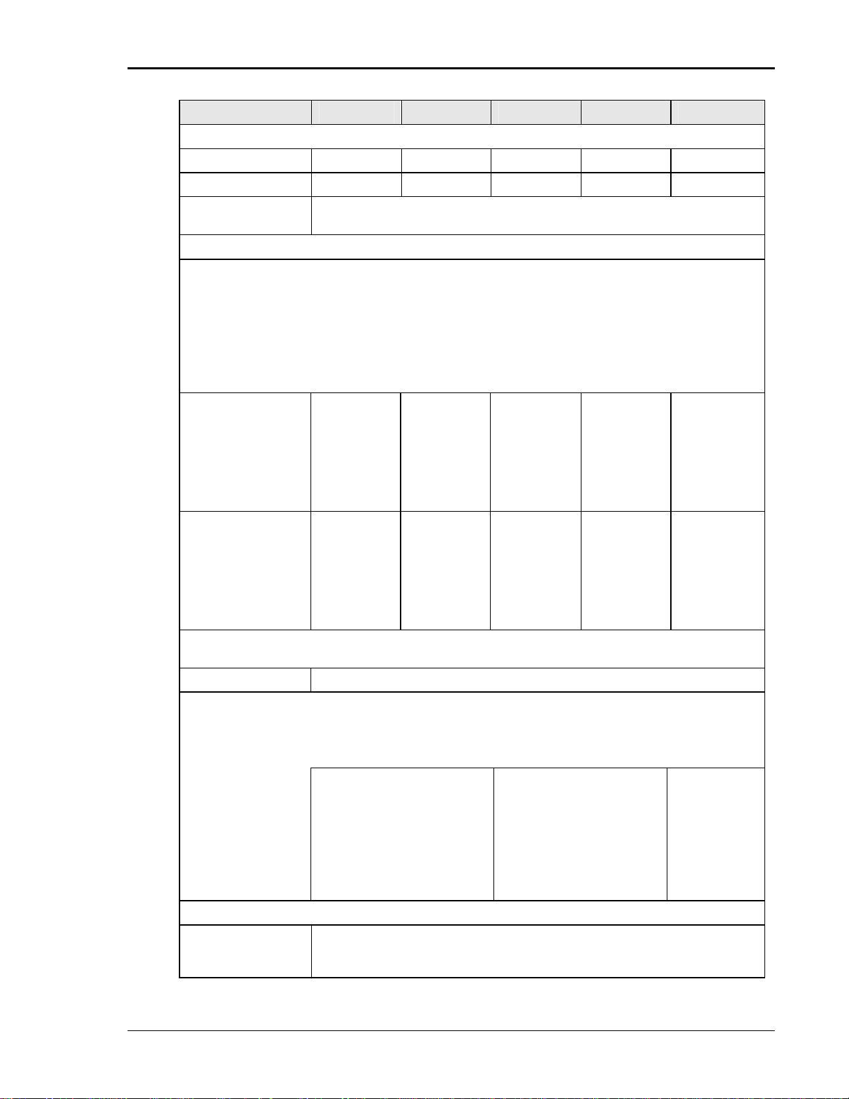
Output Parameter MX30 MX45 MX60 MX90 MX135
Power (total power for all phases, either range, at full scale voltage, maximum ambient T = 35° C)
AC Mode 30 KVA 45 KVA 60 KVA 90 KVA 135 KVA
DC Mode 20 KW 30 KW 40 KW 60 KW 90 KW
AC+DC Mode The maximum power and current in the AC+DC mode is equal to that in the DC
mode
Current
Note: Current, maximum amps indicated per phase available between 50 and 100 % of voltage
range. Maximum ambient temperate for full power operation at full-scale voltage is 35° C.
Constant Power Mode:
Operation at higher currents but constant power is possible from 80% of Voltage range
(125% of max. current) declining to 100% of maximum current at 100 % of voltage range
for short periods of time or at reduced ambient temperatures. (< 15 mins @ 30° C). See
Figure 2-3 and Figure 2-4. (Requires firmware revision 0.27 or higher.)
For MX30-3Pi model, constant power mode is supported at max ambient temperature.
AC Mode MX30-1
V Lo: 200 A
V Hi: 100 A
MX30-3, per
phase
V Lo: 66.7 A
V Hi: 33.3 A
DC Mode
AC+DC Mode
Note: Current derates linearly from 50% of voltage range to 20% of specified current at 5% of
voltage range
Current Limit mode Programmable, CC or CV mode
Repetitive Peak Current
Note: Maximum Peak Current shown. Value shown reflects absolute peak current protection level.
This level may not be reached under all load conditions. Depending on load conditions, peak current
may max out at lower levels due to amplifier output impedance.
AC Mode MX30-1 / MX30-3Pi 1Phs /
MX30-1
V Lo: 100 A
V Hi: 50 A
MX30-3, per
phase
V Lo: 33.3 A
V Hi: 16.7 A
MX45-1 / MX45-3Pi 1Phs
V Lo: 900 A
V Hi: 450 A
MX30-3 / MX30-3Pi / MX45-3
/ MX45-3Pi, per phase
V Lo: 300 A
V Hi: 150 A
MX45-1
V Lo: 300 A
V Hi: 150 A
MX45-3, per
phase
V Lo: 100 A
V Hi: 50 A
MX45-1
V Lo: 150 A
V Hi: 75 A
MX45-3, per
phase
V Lo: 50 A
V Hi: 25 A
MX60-3, per
phase
V Lo: 133 A
V Hi: 66.7 A
MX60-3, per
phase
V Lo: 66.7 A
V Hi: 33.3 A
MX60-3 / MX90-3, per
phase
V Lo: 600 A
V Hi: 300 A
MX90-3, per
phase
V Lo: 200 A
V Hi: 100 A
MX90-3, per
phase
V Lo: 100 A
V Hi: 50 A
MX135-3, per
phase
V Lo: 300 A
V Hi: 150 A
MX135-3, per
phase
V Lo: 150 A
V Hi: 75 A
MX135-3, per
phase
V Lo: 900 A
V Hi: 450 A
Frequency
Range: Standard: 16 Hz - 819.0 Hz (for –HV option range, 45 Hz – 819.0 Hz)
-LF option: 16 Hz - 500.0 Hz
-HF option: 16 Hz – 905 Hz
MX Series 15
User Manual – Rev AJ California Instruments
Output Parameter MX30 MX45 MX60 MX90 MX135
Resolution: 0.01 Hz from 16.00 to 81.91 Hz
0.1 Hz from 82.0 to 819.0 Hz
Accuracy: ± 0.01 %
Phase (3 phase mode)
Range: Phase B/C relative to phase A
0.0 to 360.0°
Resolution: 0.1°
Accuracy: 16 Hz - 100 Hz: < 1.5°
100 Hz - 500 Hz: < 2°
> 500 Hz: < 4°
Ext. Sync Mode
Input: Isolated TTL input for external frequency control. Requires 5V at 5 mA for logic
high.
Accuracy: Ext. Sync to phase A with fixed Ext. Sync Frequency input:
16 Hz - 100 Hz: < 2°
100 Hz - 500 Hz: < 3°
> 500 Hz: < 4°
Programmable Output Impedance (available on MX30-3Pi and MX45-3Pi in three phase mode only)
Range: R: 1 – 200 mOhm
L: 15 – 200 uH
Resolution: R: 1 mOhm
L: 1 uH
Accuracy: 10 % FS N/A N/A N/A
N/A N/A N/A
N/A N/A N/A
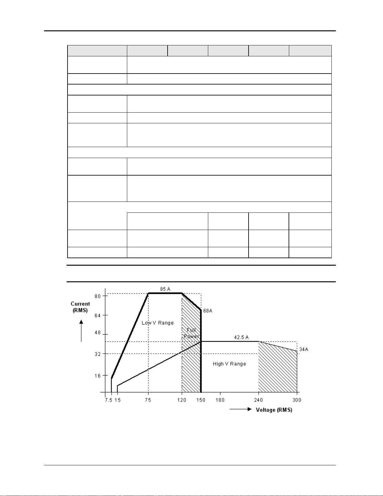
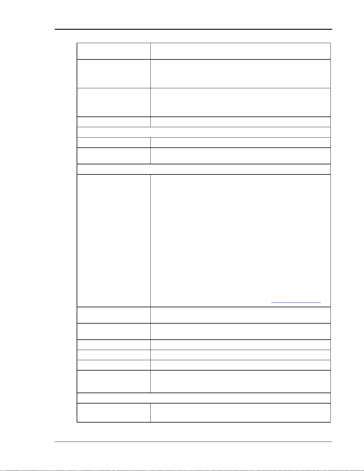
Note: Output specifications apply below the Current / Voltage rating lines shown in the
V/I rating chart below.
Figure 2-1: MX30-3 Voltage / Current Rating Chart for 150/300 V AC Ranges.
16 MX Series
User Manual – Rev AJ California Instruments
100 A
100
Current
(RMS)
80
Low V Range
60
50 A
40
High V Range
20
7.5
15
Figure 2-2: MX45-3 Voltage / Current Rating Chart for 150/300 V AC Ranges – Max Rating.
75 300
150
Voltage (RMS)
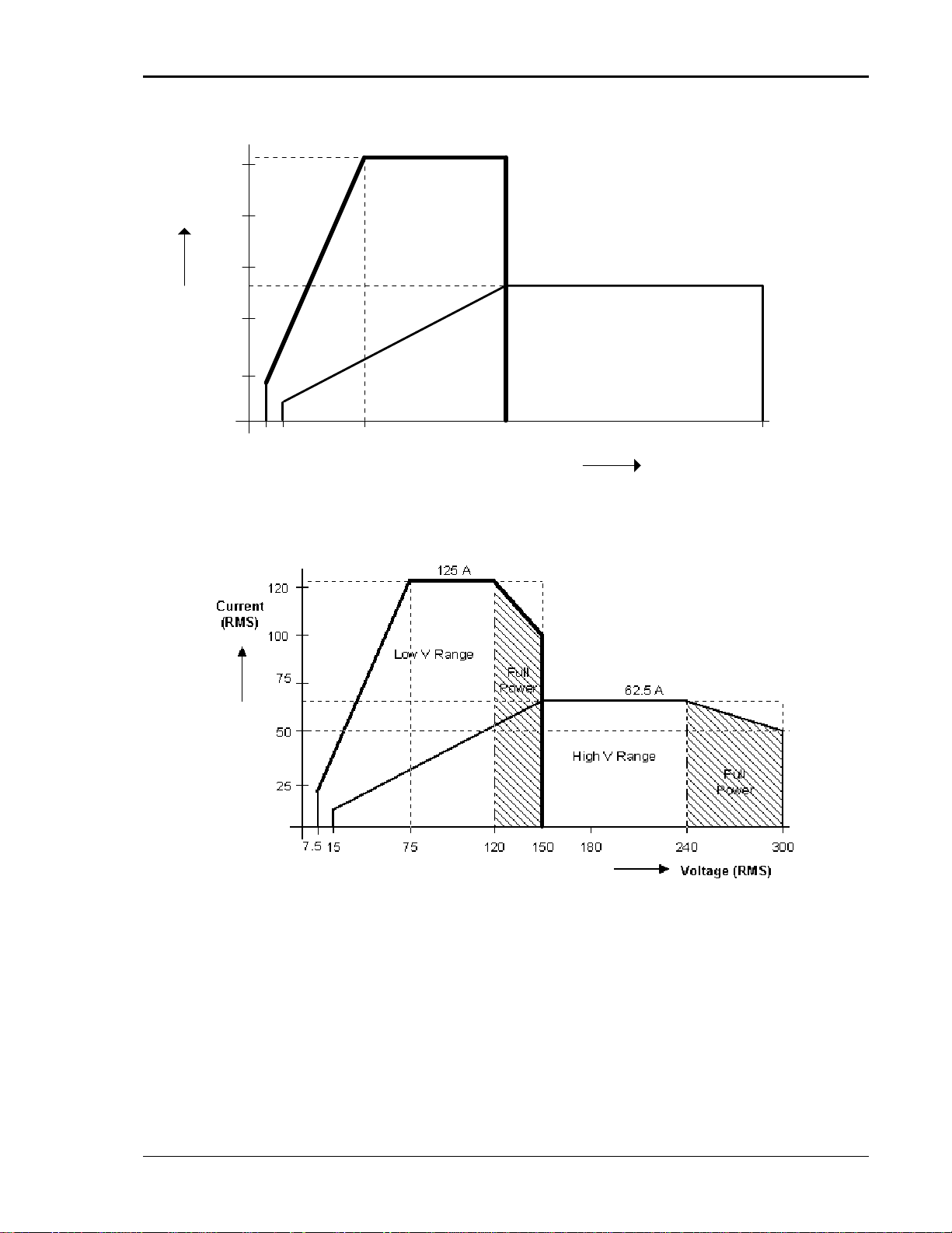
Figure 2-3: Voltage / Current Rating Chart for 150/300 V AC Ranges – Derated.
MX Series 17
User Manual – Rev AJ California Instruments
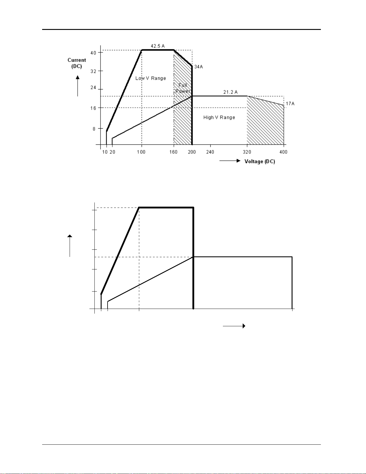
Figure 2-4: MX30-3 Voltage / Current Rating Chart for 200/400 V DC Ranges
50 A
50
Current
(DC)
40
Low V Range
30
25 A
20
High V Range
10
20
40
Figure 2-5: MX45-3 Voltage / Current Rating Chart for 200/400 V DC Ranges – Max. Rating
100 400
200
Voltage (DC)
18 MX Series
User Manual – Rev AJ California Instruments
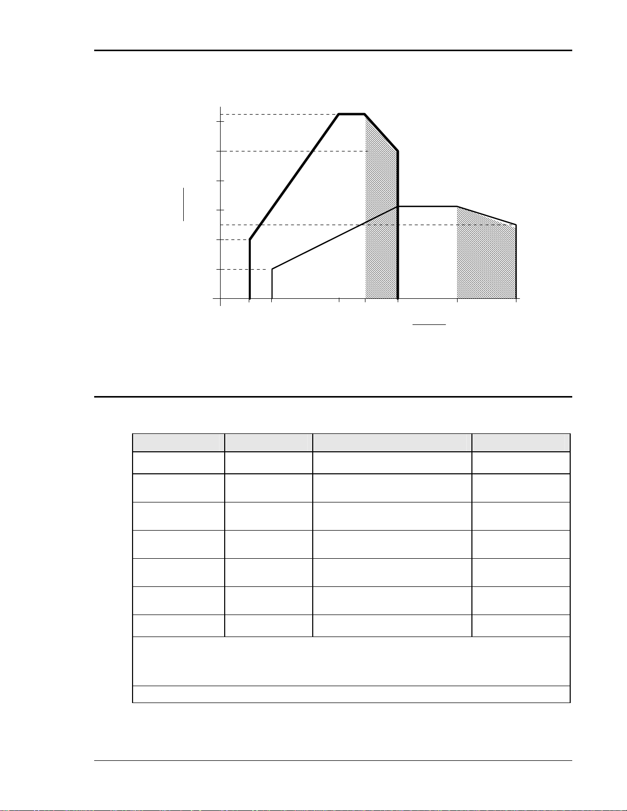
62.5 A
60
50
Current
(DC)
40
30
20
10
0
20 40 100 150 200 300 400
Full
Power
31 A
25 A
Full
Power
Voltage (DC)
Figure 2-6: Voltage / Current Rating Chart for 200/400 V DC Ranges – Derated
2.1.3 AC Measurements
Measurement specifications apply to MX30-3 / MX30-3Pi / MX45-3 or MX45-3Pi in three-phase
mode. See notes for other models and configurations.
Parameter Range
Frequency 16.00 - 820.0 Hz 0.01% + 0.01 Hz 0.01 to 81.91 Hz
RMS Voltage 0 - 400 Volts 0.05V + 0.02%, <100 Hz
RMS Current 0 - 150 Amps 0.15A + 0.02%, <100 Hz
Peak Current 0 - 400 Amps 0.15A + 0.02%, <100 Hz
VA Power 0 - 15 KVA 30 VA + 0.1%, <100 Hz
Real Power 0 - 15 KW 30 W + 0.1%, <100 Hz
Power Factor
(>0.2kVA)
Note: Accuracy specifications are valid above 100 counts. For current and power measurements,
specifications apply from 2% to 100% of measurement range. Current and Power range and accuracy
specifications are times three for MX45-1, MX60, MX90 and MX135 or MX30-3Pi / MX45-3Pi in singlephase mode.
Note: Power factor accuracy applies for PF > 0.5 and VA > 50 % of max.
Accuracy ()
0.1V + 0.02%, 100-820 Hz
0.3A + 0.02%, 100-820 Hz
0.3A + 0.02%, 100-820 Hz
60 VA + 0.1%, 100-820 Hz
60 W + 0.1%, 100-820 Hz
0.00 - 1.00 0.01, <100 Hz
0.02, 100-820 Hz
Resolution
0.1 to 500 Hz
0.01 Volt
0.01 Amp
0.01 Amp
10 VA
10 W
0.01
MX Series 19
User Manual – Rev AJ California Instruments
p
2.1.4 DC Measurements
Parameter Range
Voltage 0 - 400 Volts 0.5 Volts 0.1 Volt
Current 0 - 400 Amps 0.5 Amps 0.01 Amp
Power 0 - 10 kW 30 W 10 W
Note: Accuracy specifications are valid above 100 counts. For current and power measurements,
specifications apply from 2% to 100% of measurement range. Current and Power accuracy and
resolution s
ecifications are times three for MX30-1, MX45-1, MX60, MX90 and MX135 or MX30-3Pi /
2.1.5 Harmonic Measurements (Pi controller)
Harmonic measurement specifications apply to MX30-3, MX45-3, MX30-3Pi and MX45-3Pi in
three-phase mode. See notes for other models and configurations.
Parameter Range
Frequency fundamental 16.00 - 820 Hz 0.03% + 0.03 Hz 0.01 Hz
Frequency harmonics
MX45-3, MX45-3Pi in 3
phase mode, MX60,
MX90, MX135:
Series I
Series II
MX45-1, MX45-3Pi in 1
phase mode:
32.00 Hz – 6.67 KHz
32.00 Hz – 16 KHz
Accuracy ()
Accuracy ()
0.03% + 0.03 Hz 0.01 Hz
Resolution
Resolution
Series I
Series II
Phase 0.0 - 360.0° 2° typ. 0.5°
Voltage Fundamental 0.75V 0.01V
Harmonic 2 - 50 0.75V + 0.3% + 0.3%/kHz 0.01V
Current Fundamental 0.5A 0.1A
Harmonic 2 - 50 0.15A + 0.3% + 0.3%/kHz 0.1A
Note: For current measurements, specifications apply from 2% to 100% of measurement range.
Current range and accuracy specifications are times three for MX30-1, MX45-1, MX60, MX90 and
MX135 or MX30-3Pi / MX45-3Pi in single-phase mode.
2.1.6 System Specification
Parameter Specification
External Modulation: 0 to 10%
Synchronization
Input:
Trigger Input: External trigger source input. Requires TTL level input signal. Triggers on
Trigger Output:
32.00 Hz - 19.2 KHz
32.00 Hz – 48 KHz
Isolated TTL input for external frequency control. Requires 5V at 5 mA for
logic high.
negative edge. Response time 80 - 100 s.
Programmable through transient list system. 400 s pulse for voltage or
0.03% + 0.03 Hz 0.01 Hz
20 MX Series
User Manual – Rev AJ California Instruments
Parameter Specification
frequency change. Isolated TTL output. Output reverts to Function strobe
when not uses as Trig Out. This function is mutually exclusive with the
Function Strobe output.
Function Strobe:
Output Status: Monitors status of output relay. Isolated TTL output. High if output relay is
Non volatile memory
storage:
Waveforms Sine (Models with Standard controller)
Transients Voltage: drop, step, sag, surge, sweep
IEEE-488 Interface: SH1, AH1, T6, L3, SR1, RL2, DC1, DT1
RS232C Interface: Bi-directional serial interface
Active for any voltage or frequency program change. 400 s pulse for voltage
or frequency change. Isolated TTL output. This function is mutually exclusive
with the Trigger Output. Same output is used for Trigger Output if Trigger
Output is programmed as part of list system.
closed, low if output relay is open.
Series I: 8 complete instrument setups and transient lists, 32 events per list.
Series II: 16 complete instrument setups and transient lists, 100 events per
list.
Sine, square, clipped, user defined (Models with Pi controller)
Frequency: step, sag, surge, sweep
Voltage and Frequency: step, sweep
Syntax: IEEE 488.2 and SCPI
Response time is 10 ms (typical)
9 pin D-shell connector
Handshake: CTS, RTS
Data bits: 7, 8
Stop bits: 1,2
Baud rate: 9600 to 115,200 bps
Syntax: IEEE 488.2 and SCPI.
Note: Disconnect any USB connection when using the RS232 interface.
USB Interface: Standard USB 1.1 peripheral.
Data transfer rate: 460,800 bps
Syntax: IEEE 488.2 and SCPI.
Note: Use of the USB port to control more than one power source
from a single PC is not recommended, as communication may not be
reliable. Use GPIB interface for multiple power source control.
LAN Interface: Option –LAN. When the LAN interface is installed, the RS232 interface is
disabled.
RJ45 Connector, 10BaseT, 100BaseT or 1000BaseT,
Data transfer rate: 460,800 bps
Protocol: TCP/IP.
Syntax: IEEE 488.2 and SCP
Note: Disconnect any USB connection when using the LAN interface.
Current Limit Modes: Two selectable modes of operation:
1. Constant current mode (voltage folds back with automatic recovery)
2. Constant voltage mode with trip-off (Relays open).
MX Series 21
User Manual – Rev AJ California Instruments
2.1.7 Unit Protection
Input Over current: In-line fast acting fuses. Check fuse rating in Service and Maintenance
section. Ratings will depend on AC input configuration settings.
Circuit breaker for LV supply.
Input Over voltage: Automatic shutdown.
Input Over voltage
Transients:
Output Over current: Adjustable level constant current mode with programmable set point.
Output Short Circuit: Peak and RMS current limit.
Over temperature: Automatic shutdown.
2.2 Mechanical
Parameter Specification
Dimensions:
(for each MX chassis)
Unit Weight:
(for each MX chassis)
Material: Steel chassis with aluminum panels and covers.
Finish: Light textured painted external surfaces.
Cooling: Fan cooled with air intake on the front and exhaust to the rear.
Surge protection to withstand EN50082-1 (IEC 801-4, 5) levels.
Height: 50.0” 1270 mm
Width: 28.75” 731 mm
Depth: 34.5” 876 mm
Net: 1150 lbs / 522 Kg approximately
Shipping: 1231 lbs / 560 Kg
Panels semi-gloss polyurethane color no. 26440 (medium gray)
Fans: 6 x 225CFM.
Air displacement 22 Cu Ft/sec. Max.
approximately
Internal Construction: Modular sub assemblies.
Rear Panel
Connections:
(See section 3 for description of connections)
Cable entry and strain relieve for AC input wiring
Cable entry and strain relieve for output wiring
External sense terminal block (Remote voltage sense)
System interface (2x)
Clock and Lock BNC's (requires -LKM or -LKS options)
RS232, USB, GPIB, LAN (option)
Trigger In BNC
Trigger Out BNC
Function Strobe BNC
Output Status
22 MX Series

User Manual – Rev AJ California Instruments
2.3 Environmental
Parameter Specification
Operating Temp:
Storage Temp:
Altitude: < 2000 meters
Relative Humidity:
Installation/Over voltage
Category:
Pollution Degree: 2
Indoor Use Only
Vibration: Designed to meet NSTA 1A transportation levels.
Shock: Designed to meet NSTA 1A transportation levels.
2.4 Regulatory
Electromagnetic
Emissions and Immunity:
Acoustic Noise: 65 dBA maximum at 0% to 50% load, 75 dBA maximum greater than
0° to +35 C. (Except in CP mode).
+32° to +104° F.
-40° to +85 C.
-40° to +185° F.
0-95 % RAH, non-condensing maximum for temperatures up to 31C
decreasing linearly to 50% at 40C.
Designed to meet EN50081-2 and EN50082-2 European Emissions and
Immunity standards as required for the “CE” mark.
50% load to 100% load. Measured at one meter.
Safety: Designed to EN 61010-1 European safety standards as required for the
2.5 Front Panel Controls
Controls:
Shuttle knob: Allows continuous change of all values including output calibration and
Decimal keypad: A conventional decimal keypad facilitates quick entry of numerical values
Up/down arrow keys: A set of up and down arrow keys is used to move the cursor position in all
Function keys: Measure key will display most measurement values. Program key will
“CE” mark.
range change.
such as voltage, current limit, etc. The large blue enter key will make the
value you enter effective. Using the SET key allows the user to preset all
parameter values and update them all at once by pressing the Enter key.
menus. This allows quick selection of the desired function or parameter.
show all program parameters. Output on/off key for output relay control.
Phase key will switch display to show program and measured values for
each phase.
MX Series 23
User Manual – Rev AJ California Instruments
)
Displays:
LCD graphics display: A large high contrast LCD display with backlight provides easy to read
guidance through all setup operations. An adjustable viewing angle
makes it easy to read from all practical locations.
Status indicators: Large and bright status indicators inform the user of important power
source conditions. The Remote lamp informs the user that the unit is
under remote control. The Overload lamp indicates that excessive
current is being drawn at the output. The Over temperature lamp
illuminates when internal heat sink temperatures are too high. The Hi
Range indicator is lit any time the unit is switched to the high voltage
range. The Output On/Off indicator is on when the power source output
relays are closed.
2.6 Special Features and Options
Controller Features
Mode: Switches between 1 and 3 phase outputs. This mode is available on
models MX30-3Pi and MX45-3Pi only.
Parallel Operation: Up to three units can be paralleled in a three-phase configuration (with
one master controller and one or two auxiliary units). (MX60, MX90 and
MX135). Only the master unit requires a controller in this setup. The
auxiliary units are controlled through the system interface.
Clock and Lock Mode:
(Option -LKM and -LKS
required).
Controller: Programmable controller front panel assembly.
Output Relay: Standard output relay feature to isolate power source from the load.
Output On/Off: The output relay can be used to quickly disconnect the load. A green
Firmware / Software Optio ns
- 704 Mil Std 704D & E test firmware.
- 160 RTCA/DO-160D test firmware
- 411 IEC 61000-4-11 test firmware (Pre-compliance)
- 413 IEC 61000-4-13 test firmware
Three units (all with controllers) can be connected in a three-phase
configuration using CLOCK and LOCK connections. Each unit requires
its own controller in this configuration. One unit acts as the master and
provides the reference clock to the auxiliary units.
Note: This option cannot be combined with –HF option.
status indicator displays the status of the output relay.
Mil Std 704A, B, C, & F test software (refer to Avionics Software Manual
P/N 4994-971 for details).
Note: Requires use of MXGui Windows application software provided on
CD ROM CIC496.
RTCA/DO-160E test software (refer to Avionics Software Manual P/N
4994-971 for details)..
Note: Requires use of MXGui Windows application software provided on
CD ROM CIC496.
-A350 Airbus A350 ABD0100.1.8.1 Test software (refer to Avionics Software
Manual P/N 4994-971 for details)..
Note: Requires use of MXGui Windows application software provided on
CD ROM CIC496.
-ABD Airbus A380 ABD0100.1.8 Test software (refer to Avionics Software
Manual P/N 4994-971 for details
..
24 MX Series
User Manual – Rev AJ California Instruments
j
Note: Requires use of MXGui Windows application software provided on
CD ROM CIC496.
-AMD Airbus AMD24C Test software (refer to Avionics Software Manual P/N
4994-971 for details)..
Note: Requires use of MXGui Windows application software provided on
CD ROM CIC496.
-B787 Boeing 787 Test software (refer to Avionics Software Manual P/N 4994971 for details)..
Note: Requires use of MXGui Windows application software provided on
CD ROM CIC496.
-WHM Watt Hour Measurements (Accuracy and Resolution. See Sec. 2.6.3.)
Output Voltage Range Options
- HV Adds 400 V AC only output range.
- XV Adds customer specified AC only output range. Contact factory for
details.
Misc. Options
-ES Emergency Shut off switch. This option key lock push button is installed
on the front panel of the master MX if ordered with the MX system. When
pushed in, the main AC contactor is opened disconnecting the AC input
power to the MX input transformer. Note that the controller (and LCD
display) will still be powered up but no power is available to the amplifiers
and there will be no output power either. The controller runs off the LV
supply, which must be turned off with the front panel breaker.
After the ES has been pushed, the provided key will be required to
release it. Once the ES button has been released, the MX must be
powered down using the front panel circuit breaker and turned back on to
start up again.
Note: For multibox MX Systems (MX90 and up with more than one
controller and front panel controls, each of which having an ES
emergency switch, to connect a BNC cable between the cabinets for the
ES connection. For 3 or more cabinets with controller, this BNC can be
daisy chained using BNC T connectors.
Note: Do not misplace the 2 keys provided, as no duplicates are
available from CI. If lost, the ES switch must be replaced. In that case,
contact California Instruments customer service. (
support@calinst.com ).
-HF Increases maximum output frequency to 905 Hz.
Note: This option cannot be combined with –LKM or -LKS option.
-LAN Adds Ethernet interface (RJ45 connector) for local area network
connection..
-LF Limits maximum output frequency to 500 Hz.
-LKM Clock and Lock system, Master. (Not available with –HF option)
-LKS Clock and Lock system, Auxiliary. (Not available with –HF option)
-MB Multi-box Option. Provides additional controllers in Auxiliary units of
multi-cabinet configurations (MX60, MX90, MX135) to allow individual
MX45 units to be used stand-alone.
External Accessories (External to MX chassis)
7003-416-1
Input / Output wiring junction box. Connects two to six three-phase MX45
cabinet outputs, neutral and ground to a common output terminal block
housed in a metal enclosure
unction box. Can also be used to connect
MX Series 25
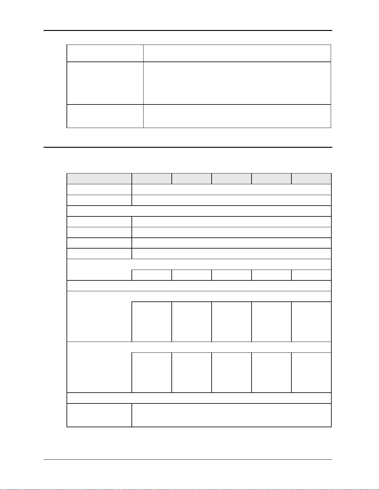
User Manual – Rev AJ California Instruments
multiple MX chassis to common AC input service. See section 3.13 for
details.
7003-424-1
7003-426-1
2.6.1 -HV Option Specifications
The -HV option provides an AC only output range of 0 to 400 Vac L-N. Specifications unique to
the -HV option are shown in the table below.
Output Parameter MX30 MX45 MX60 MX90 MX135
Modes
Pi Controller AC
Voltage:
Ranges (L-N): 0 -400 V
Resolution: 0.1 V
Accuracy: ± 0.25% of Full Scale / ± 1.0 Vac rms
Output noise filter, 3 phase + neutral. May be used to reduce output
noise of MX30 or MX45 when testing EUT’s for conducted emissions.
This is an external filter that attenuates the 250 KHz ripple frequency on
the MX output by > 20 dB. The filter is rated for 125A per phase and 800
Hz. For multi-box configurations, one filter is required per chassis.
Connects to MX30 or MX45 three-phase output terminal only.
Output fuse box. Provides added protection for MX system configurations
consisting of more than 2 MX cabinets. (MX135, MX180, MX225 and
MX270).
Output Coupling AC coupled
Power (total power for all phases, either range, at full scale voltage)
AC Mode 30 KVA 45 KVA 60 KVA 90 KVA 135 KVA
Current
Note: Current, maximum amps per phase available between 50 and 100 % of voltage range.
MX30-1
76.5 A
MX30-3, per
phase
25.5 A
Peak Current
AC Mode MX30-1
337.5 A
MX30-3, per
phase
112.5 A
Frequency:
Range: 45 Hz – 819 Hz
with –LF option: 45 Hz – 500 Hz
with –HF option: 45 Hz – 905 Hz (see also –HF option specification.)
MX45-1
112.5 A
MX45-3, per
phase
37.5 A
MX45-1
337.5 A
MX45-3, per
phase
112.5 A
MX60-3, per
phase
50 A
MX60-3, per
phase
225 A
MX90-3, per
phase
75 A
MX90-3, per
phase
225 A
MX135-3,
per phase
112.5 A
MX135-3,
per phase
337.5 A
26 MX Series
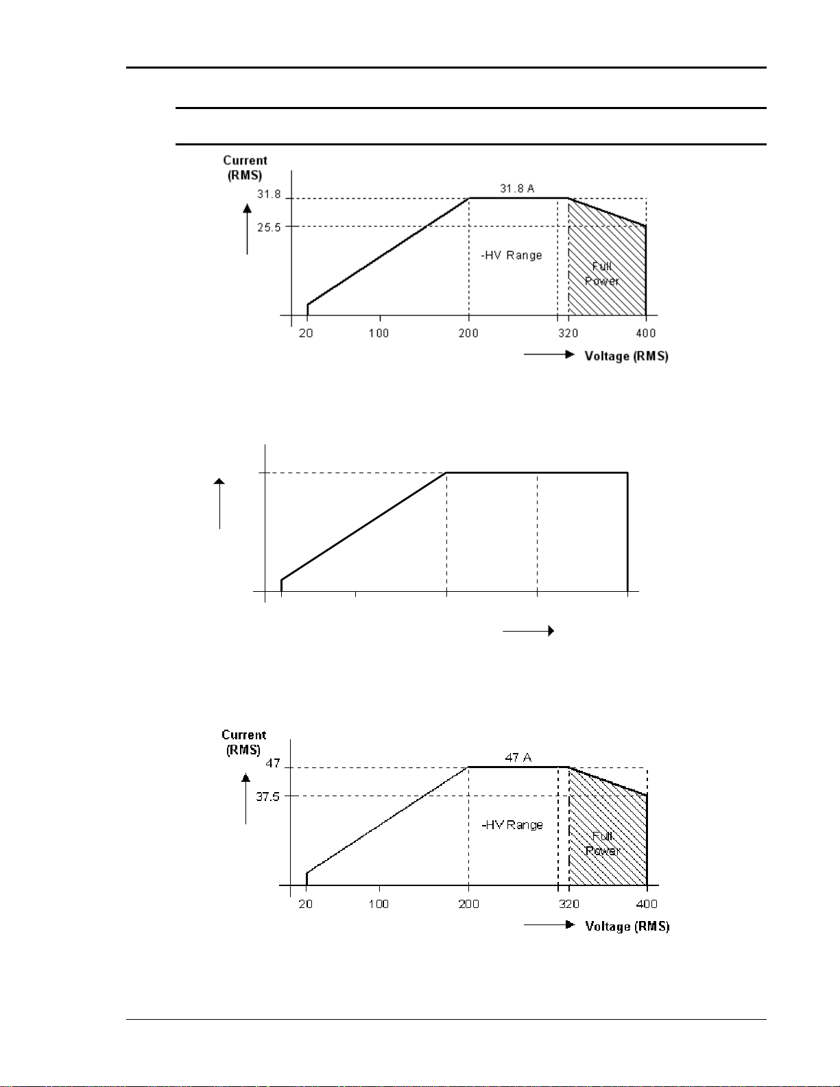
User Manual – Rev AJ California Instruments
Note: Output specifications apply below the Current / Voltage rating lines shown in the
V/I rating chart below.
Figure 2-7: MX30-3 Voltage / Current Rating Chart, -HV Option
Current
(RMS)
37.5 A
37.5
-HV Range
20
100 200 300 400
Voltage (RMS)
Figure ting.
2-8: MX45-3 Voltage / Current Rating Chart, -HV Option – Max. Ra
Figure 2-9: Voltage / Current Rating Chart, -HV Option – Derated.
MX Series 27
User Manual – Rev AJ California Instruments
2.6.2 -XV Option Specifications
Consult factory for -XV option specifications.
2.6.3 -HF Option Specifications
The -HF option extends the maximum available output frequency from 819 Hz to 905 Hz. Some
restrictions are in effect at this increased output frequency level.
All other specifications of the MX45 system remain unchanged if this option is installed except
as noted in the table below.
-HF Option:
Frequency
Range: -HF option: 16 Hz - 905 Hz
Resolution: 0.01 Hz < from 16.00 to 81.92 Hz
0.1 Hz > from 82.0 to 819.2 Hz
1 Hz > from 820 to 905 Hz
Accuracy: ± 0.01 %
Phase
Accuracy: 16 - 100 Hz: < 1.5°
100 - 500 Hz: < 2°
500 – 819 Hz: < 4°
819 – 905 Hz: < 5°
Voltage
High Voltage Range Maximum voltage at 905 Hz is 290 Vrms
Maximum frequency at 300 Vrms is 875 Hz
See Figure 2-10
Low Voltage Range Maximum voltage at 905 Hz is 145 Vrms
Maximum frequency at 150 Vrms is 875 Hz
See Figure 2-11.
-HV Voltage Range Maximum voltage at 905 Hz is 386 Vrms
Maximum frequency at 400 Vrms is 875 Hz .
Note: If the voltage or frequency settings shown here are exceeded for
any length of time (> 1 sec), the MX may shut down generating an over
temperature fault to protect itself.
28 MX Series
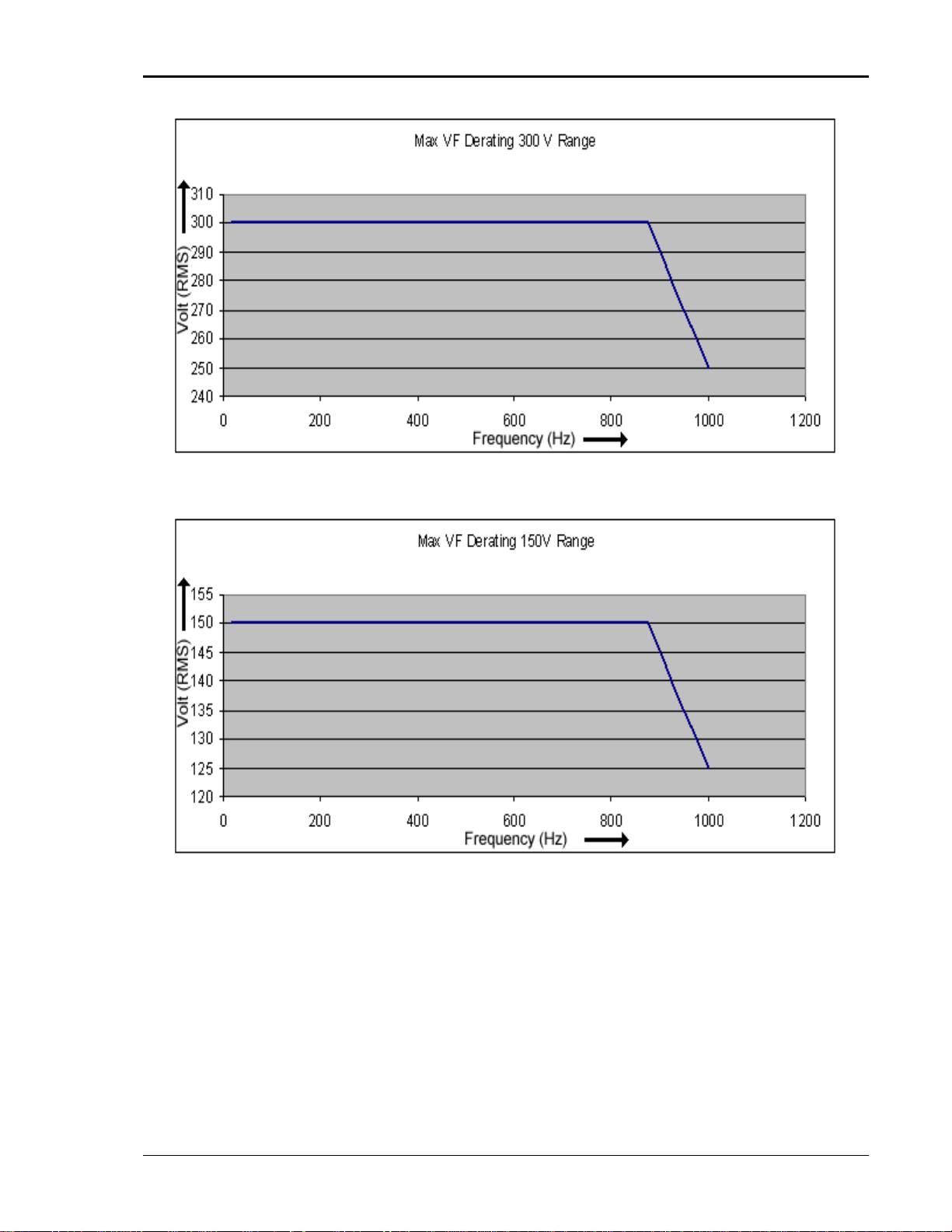
User Manual – Rev AJ California Instruments
Figure 2-10: -HF Option Voltage Frequency Rating 300V range
Figure 2-11: -HF Option Voltage Frequency Rating 150V range
MX Series 29

User Manual – Rev AJ California Instruments
2.6.4 -LF Option Specifications
The -LF option limits the maximum available output frequency to 500 Hz. All other specifications
of the MX45 system remain unchanged if this option is installed.
2.6.5 WHM Option Specifications
Watt-hour measurement mode:
Accuracy:
0-6.000KW 0.01KWH + 0.1% <100 Hz
0.02KWH +0.1% 100-819 Hz
>6.000KW Times three of the above specification
Resolution:
0.001 KWH
30 MX Series
 Loading...