

California Instruments FCS Series II User Manual

Revision B
December 2007
by California Instruments.
All rights reserved.
Copyright © 2007
P/N 5000-967
FCS Series II
AC Power Source
User Manual
TEL: +1 (858) 677-9040
FAX: +1 (858) 677-0940
Email:
Web Site:
sales@calinst.com
http://www.calinst.com

User Manual – Rev B FCS Series II
Refers to:
FCS Series II AC Power Source/Analyzers
Models:
Single chassis: FCS18-1, FCS18-3
Multiple chassis: FCS36-3, FCS54-3
Manual revision: B.
Copyright © 2007 California Instruments Company
California Instruments 2

User Manual – Rev B FCS Series II
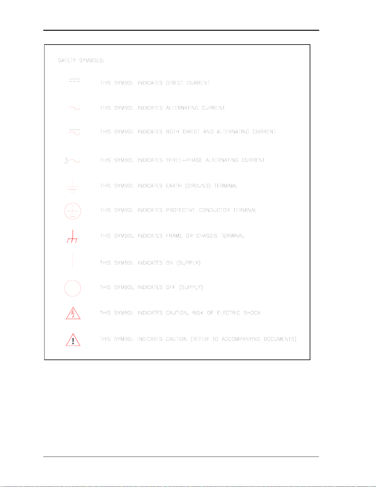
SAFETY SUMMARY
This power source contains high voltage and current circuits, which are potentially lethal.
Because of its size and weight, mechanical stability must be ensured. The following
safety guidelines must be followed w h en operating or servicing this equipment. These
guidelines are not a substitute for vigilance and common sense. California Instruments
assumes no liability for the customer’s failure to comply with these requirements. If the
power source is used in a manner not specified b y California In struments, the protection
provided by the equipment may be impaired.
BEFORE APPLYING POWER
1. Verify the correct three phase input voltage is applied to the unit. Input ratings are shown
on the model and serial number tag located at the rear of the unit.
2. The chassis and cabinet of this power source must be grounded to minimize shock hazard.
A chassis ground is provided at the input terminal block. This is located in the front of the
cabinet on the lower left hand side. The lower front cover panel must be removed to
access the line input and ground connections. The chassis ground must be connected to
an electrical ground through an insulated wire of sufficient gauge.
FUSES
Use only fuses of the specified current, voltage, and protection speed (slow blow, normal blow,
fast blow) rating. Do not short out the fuse holder or use a repaired fuse.
DO NOT OPERATE IN A VOLATILE ATMOSPHERE
Do not operate the power source in the presence of flammable gases or fumes.
DO NOT TOUCH ENERGIZED CIRCUITS
Disconnect the power cable before servicing this equipment. Even with the power cable
disconnected, high voltage can still exist on some circuits. Discharge these voltages before
servicing. Only qualified service personnel may remove covers, replace components or make
adjustments.
DO NOT SERVICE ALONE
Do not remove covers, replace components, or make adjustments unless another person, who
can administer first aid, is present.
DO NOT EXCEED INPUT RATINGS
Do not exceed the rated input voltage or frequency. Additional hazards may be introduced
because of component failure or improper operation.
DO NOT MODIFY INSTRUMENT OR SUBSTITUTE PARTS
Do not modify this instrument or substitute any parts. Additional hazards may be introduced
because of component failure or improper operation.
MOVING THE POWER SOURCE
When moving the power source, observe the following:
1. Remove all AC power to unit.
2. Do not attempt to lift by hand. Raise the levelers and push the unit using two people to
prevent injury or use forklift equipment with a qualified operator.
ALLOW CAPACITORS TO DISCHARGE
Capacitors in the power source may hold a hazardous electrical charge even if the power source
has been disconnected from the mains supply. Allow capacitors to discharge to a safe voltage
before servicing internal circuits or touching exposed pins of the mains supply connectors.
California Instruments 3
User Manual – Rev B FCS Series II
California Instruments 4

User Manual – Rev B FCS Series II
WARRANTY INFORMATION
CALIFORNIA INSTRUMENTS CORPORATION warrants each instrument manufactured by them to be
free from defects in material and workmanship for a period of one year from the date of shipment to the
original purchaser. Excepted from this warranty are fuses and batteries that carry the warranty of their
original manufacturer where applicable. CALIFORNIA INSTRUMENTS will service, replace, or adjust
any defective part or parts, free of charge, when the instrument is returned freight prepaid, and when
examination reveals that the fault has not occurred because of misuse, abnormal conditions of
operation, user modification, or attempted user repair. Equipment repaired beyond the effective date of
warranty or when abnormal usage has occurred will be charged at applicable rates. CALIFORNIA
INSTRUMENTS will submit an estimate for such charges before commencing repair, if so requested.
VOIDED WARRANTY
Any misuse or abuse of, as well as any modifications or changes made to any California Instruments
product will automatically void the factory warranty. Removing non-normal use related covers or any
sealed covers or lids also automatically voids factory warranty unless express written or email
authorization is obtained from the customer service department in advance. The customer service
department can be reached via email at
support@calinst.com.
SERVICE PROCEDURE
If a fault develops, notify CALIFORNIA INSTRUMENTS at support@calinst.com or its local
representative, giving full details of the difficulty, including the model number and serial number. On
receipt of this information, service information or a Return Material Authorization (RMA) number will be
given. Add the RMA number furnished to the shipping label. Pack the instrument carefully to prevent
transportation damage, affix label to shipping container, and ship freight prepaid to the factory.
CALIFORNIA INSTRUMENTS shall not be responsible for repair of damage due to improper handling
or packing. Instruments returned without RMA No. or freight collect
Instruments discretion. Instruments repaired under Warranty will be returned either via prepaid surface
freight or low cost airfreight at California Instruments discretion. Instruments repaired outside the
Warranty period will be returned freight collect, Ex Works CALIFORNIA INSTRUMENTS 9689 Towne
Centre Drive, San Diego, CA 92121-1964. If requested, an estimate of repair charges will be made
before work begins on repairs not covered by the Warranty.
may be refused at California
DAMAGE IN TRANSIT
The instrument should be tested when it is received. If it fails to operate properly, or is damaged in any
way, a claim should be filed immediately with the carrier. The claim agent should obtain a full report of
the damage, and a copy of this report should be forwarded to us by fax or email (Fax: 858 677 0940,
Email:
support@calinst.com). CALIFORNIA INSTRUMENTS will prepare an estimate of repair cost
and repair the instrument when authorized by the claim agent. Please include model number and
serial number when referring to the instrument.
SPARE PARTS
To order spare parts, user manuals, or determine the correct replacement part for your California
Instruments products, please contact the Customer Service department by phone at + 1 858 677 9040,
press 2 or by email
support@calinst.com.
California Instruments 5

User Manual – Rev B FCS Series II
Table of Contents
Introduction................................................................................................................................... 10
1.
1.1 General Description......................................................................................................................... 10
1.2 Manual organization and format ...................................................................................................... 11
2. Specifications ............................................................................................................................... 12
2.1 Electrical.......................................................................................................................................... 12
2.2 Mechanical ...................................................................................................................................... 18
2.3 Environmental ................................................................................................................................. 18
2.4 Front Panel Controls ....................................................................................................................... 19
2.5 Special Features ............................................................................................................................. 20
2.6 Available Options ............................................................................................................................ 21
3. Unpacking and Installation ........................................................................................................... 26
3.1 Unpacking ....................................................................................................................................... 26
3.2 Power Requirements....................................................................................................................... 26
3.3 Mechanical Installation .................................................................................................................... 26
3.4 AC Input Wiring – TB1..................................................................................................................... 29
3.5 Output Connections......................................................................................................................... 31
3.6 Connectors - Rear Panel................................................................................................................. 37
3.7 Basic Initial Functional Test............................................................................................................. 42
3.8 Multi-box Configurations (-MB Option) ............................................................................................ 44
3.9 Clock and Lock Mode (-LKM/-LKS Option)...................................................................................... 45
3.10 Remote Control Interfaces .............................................................................................................. 46
4. Front Panel Operation .................................................................................................................. 47
4.1 Tour of the Front Panel ................................................................................................................... 47
4.2 Menu Structure................................................................................................................................ 54
4.3 Output Programming ....................................................................................................................... 75
4.4 Waveform Management (-ADV Option required)............................................................................. 77
4.5 Measurements................................................................................................................................. 80
4.6 Harmonic Analysis........................................................................................................................... 81
4.7 Transient Programming................................................................................................................... 81
4.8 Setting the Power-on Initialization Values ....................................................................................... 86
4.9 Remote Inhibit Function .................................................................................................................. 87
5. Principle of Operation................................................................................................................... 88
5.1 Overall Description .......................................................................................................................... 88
5.2 Controller Assembly ........................................................................................................................ 88
5.3 Power Amplifiers Assembly............................................................................................................. 90
6. Calibration..................................................................................................................................... 94
6.1 Recommended Calibration Equipment ............................................................................................ 94
6.2 Calibration Screens ......................................................................................................................... 96
6.3 Measurement Calibration ................................................................................................................ 96
6.4 Output Calibration ........................................................................................................................... 99
6.5 Phase Offset Calibration ................................................................................................................. 99
6.6 Non-Routine Output Gain Calibration............................................................................................ 100
6.7 Load Resistance by Model ............................................................................................................ 102
California Instruments 6

User Manual – Rev B FCS Series II
7. Service........................................................................................................................................ 103
7.1 Cleaning.........................................................................................................................................103
7.2 General..........................................................................................................................................103
7.3 Basic operation ..............................................................................................................................103
7.4 Isolating amplifier failures in multi-box systems ............................................................................. 106
7.5 Advanced Troubleshooting. ...........................................................................................................107
7.6 Factory Assistance ........................................................................................................................110
7.7 Fuses.............................................................................................................................................110
7.8 Replaceable Parts .........................................................................................................................111
8. Option -160: RTCA / DO-160D................................................................................................... 113
8.1 General..........................................................................................................................................113
8.2 Initial Setup....................................................................................................................................113
8.3 Tests Performed ............................................................................................................................ 113
8.4 Front Panel Operation -160 ...........................................................................................................114
8.5 Normal State tests .........................................................................................................................115
8.6 EMERGENCY TEST .....................................................................................................................123
8.7 ABNORMAL TEST ........................................................................................................................125
9. Option –160: RTCA/DO-160 Rev E Tests (Software) ................................................................ 128
10. Option -704: MIL-STD 704 Rev D through F (MIL704 Mode) ....................................................129
10.1 General..........................................................................................................................................129
10.2 Initial Setup....................................................................................................................................129
10.3 Test Revision.................................................................................................................................129
10.4 Tests Performed ............................................................................................................................ 130
10.5 Front Panel Operation MIL704.......................................................................................................131
10.6 Steady State Tests ........................................................................................................................132
10.7 Emergency Test.............................................................................................................................135
10.8 Abnormal Test ...............................................................................................................................136
11. Option –704F: MIL-STD 704 Rev A through F (MS704 mode) .................................................. 138
11.1 General..........................................................................................................................................138
11.2 Initial Setup....................................................................................................................................138
11.3 Test Revision.................................................................................................................................138
11.4 Power Group Reference ................................................................................................................ 139
11.5 Available Tests ..............................................................................................................................139
11.6 Front Panel Operation MS704 .......................................................................................................141
11.7 Test Steps and Execution Times Summary...................................................................................144
11.8 MS704 Operation Using the LxGui Software .................................................................................191
12. Option –ABD: Airbus ABD0100.1.8 Test (Software) .................................................................. 199
13. Option –AMD: Airbus AMD24C Test (Software) ........................................................................ 200
14. Option –B787: Boeing 787B3-0147 Test (Software) .................................................................. 201
15. Error Messages .......................................................................................................................... 202
16. Index ........................................................................................................................................... 208
California Instruments 7

User Manual – Rev B FCS Series II
List of Figures
Figure 2-1: Distortion as a function of Output Frequency.................................................................................... 14
Figure 2-2: Current versus Voltage operating range. .......................................................................................... 15
Figure 2-3: Voltage / Frequency Rating............................................................................................................... 15
Figure 3-1: Rear Panel Connector Locations ...................................................................................................... 28
Figure 3-2: FCS36/2-3 Wiring diagram - Three Phase mode .............................................................................. 33
Figure 3-3: FCS36/2-1 Wiring diagram - Single Phase mode ............................................................................. 34
Figure 3-4: FCS54/3-3 Wiring Diagram - Three Phase mode ............................................................................. 35
Figure 3-5: FCS54/3-1 Wiring Diagram - Single Phase mode............................................................................. 36
Figure 3-6: USB Connector pin orientation.......................................................................................................... 40
Figure 3-7: Functional Test Setup ....................................................................................................................... 42
Figure 4-1: Shuttle Knob ..................................................................................................................................... 50
Figure 4-2: Menu Keys........................................................................................................................................ 51
Figure 4-3: Measurement Screen........................................................................................................................ 53
Figure 4-4: PROGRAM Menu ............................................................................................................................. 58
Figure 4-5: CONTROL Menus............................................................................................................................. 59
Figure 4-6: MEASUREMENT Screen.................................................................................................................. 62
Figure 4-7: Selecting a Waveform....................................................................................................................... 77
Figure 4-8: Selecting Waveforms for Single Phase or All Phases....................................................................... 77
Figure 4-9: Waveform Crest Factor Affects Max. rms Voltage ............................................................................ 78
Figure 4-10: Pulse Transients ............................................................................................................................. 82
Figure 4-11: List Transients................................................................................................................................. 82
Figure 4-12: Sample Transient Output Sequence ............................................................................................... 84
Figure 4-13: Switching Waveforms in a Transient List ........................................................................................ 85
Figure 4-14: TRANSIENT Menu.......................................................................................................................... 85
Figure 5-1: FCS System Block Diagram.............................................................................................................. 89
Figure 5-2: Power Amplifier - Exploded View. ..................................................................................................... 92
Figure 6-1: Calibration Setup .............................................................................................................................. 95
Figure 6-2: Current Limit board access panel ................................................................................................... 100
Figure 6-3: Location of Gain pot adjustments and TP1 through TP4 ................................................................ 100
Figure 7-1: Front panel location ........................................................................................................................ 109
Figure 7-2: Fuse Locations................................................................................................................................ 109
Figure 8-1: Application Menu ............................................................................................................................ 114
Figure 8-2: DO160 Main Menus ........................................................................................................................ 114
Figure 8-3: Normal state screens ...................................................................................................................... 115
Figure 8-4: Voltage Modulation - Frequency characteristics ............................................................................. 118
Figure 8-5: Frequency Modulation..................................................................................................................... 119
Figure 8-6: Power Interrupt ............................................................................................................................... 120
Figure 8-7: Power Interrupt for Group2/A(NF) and Group3/A(WF).................................................................... 121
Figure 8-8: Emergency Screens........................................................................................................................ 123
Figure 8-9: Abnormal Screen ............................................................................................................................ 125
Figure 10-1: Applications Menu......................................................................................................................... 131
Figure 10-2: MIL704 Menu................................................................................................................................ 131
Figure 10-3: Steady State Menu ....................................................................................................................... 132
Figure 10-4: Emergency Menu.......................................................................................................................... 135
Figure 10-5: Abnormal Screens ........................................................................................................................ 136
Figure 11-1: Applications Menu......................................................................................................................... 141
Figure 11-2: MIL704 Run/Status ....................................................................................................................... 141
Figure 11-3: Mil704 Run/Status......................................................................................................................... 141
Figure 11-4: Revision/Group Menu ................................................................................................................... 142
Figure 11-5: Test selection Menu...................................................................................................................... 142
Figure 11-6: Section and Test Condition........................................................................................................... 143
Figure 11-7:Steady State frequency.................................................................................................................. 143
Figure 11-8: Required SAC-106 Test Setup...................................................................................................... 146
Figure 11-9: Required TAC-106 Test Setup...................................................................................................... 159
Figure 11-10: Required SVF-106 Test Setup. ................................................................................................... 172
Figure 11-11: Required TVF-106 Test Setup. ................................................................................................... 180
Figure 11-12: Required SXF-106 Test Setup. ................................................................................................... 187
Figure 11-13: LxGui MS704 Option Screen ...................................................................................................... 192
Figure 11-14: LxGui MS704 Option EUT Performance Test Screen - Measurements ...................................... 193
California Instruments 8

User Manual – Rev B FCS Series II
Figure 11-15: LxGui MS704 Option EUT Performance Test Screen - Waveforms ............................................ 195
List of Tables
Table 3-1: AC Input transformer, EMI Filter and CB configurations.....................................................................30
Table 3-2: FCS18 Rear Panel Connections.........................................................................................................31
Table 3-3: Wire Gauge table................................................................................................................................32
Table 3-4: Output Terminal connections.............................................................................................................. 32
Table 3-5: AC Input Terminal Block Connection Description ............................................................................... 37
Table 3-6: External Sense Connector.................................................................................................................. 37
Table 3-7: Output Terminal connections.............................................................................................................. 37
Table 3-8: DB15 Auxiliary I/O Connector............................................................................................................. 38
Table 3-9: BNC Connectors.................................................................................................................................38
Table 3-10: RS232C Connector ..........................................................................................................................39
Table 3-11: USB Connector pin out.....................................................................................................................40
Table 3-12: RJ45 LAN Connector pin out. ...........................................................................................................41
Table 3-13: Full Load Resistance. ....................................................................................................................... 43
Table 4-1: Menu Tree .......................................................................................................................................... 57
Table 4-2: Sample Transient List.........................................................................................................................84
Table 4-3: Factory Default Power on Settings .....................................................................................................86
Table 4-4: Factory Default Power on Settings .....................................................................................................87
Table 6-1: Calibration Load Values by model and voltage range.........................................................................97
Table 6-2: Output Calibration Coefficients - Factory Defaults..............................................................................99
Table 6-3: Output Calibration Coefficients - Factory Defaults............................................................................101
Table 7-1: Basic Symptoms............................................................................................................................... 103
Table 7-2: Replaceable Parts and Assemblies .................................................................................................. 112
Table 8-1: Normal Voltage and Frequency minimum.........................................................................................116
Table 8-2: Normal Voltage and Frequency Maximum........................................................................................116
Table 8-3: Normal Voltage Unbalance...............................................................................................................117
Table 8-4: Airbus mode voltage modulation. .....................................................................................................117
Table 8-5: Normal VoltageSurge Sequence ......................................................................................................121
Table 8-6: Normal Frequency Transient Sequence ...........................................................................................122
Table 8-7: Normal Frequency Variation Sequence ............................................................................................122
Table 8-8: Emergency Voltage and Frequency Minimum .................................................................................. 123
Table 8-9: Emergency Voltage and Frequency Maximum ................................................................................. 123
Table 8-10: Emergency Voltage Unbalance ......................................................................................................124
Table 8-11: Abnormal Voltage Minimum............................................................................................................125
Table 8-12: Abnormal Voltage Maximum...........................................................................................................125
Table 8-13: Abnormal Voltage Unbalance ......................................................................................................... 126
Table 8-14: Abnormal Frequency Transient ......................................................................................................127
Table 10-1: Steady state voltage ....................................................................................................................... 132
Table 10-2: Steady state frequency...................................................................................................................133
Table 10-3: Frequency Modulation .................................................................................................................... 133
Table 10-4: Abnormal Over Frequency..............................................................................................................137
Table 10-5: Abnormal Under Frequency............................................................................................................137
Table 11-1: DO160 Test Groups .......................................................................................................................139
Table 11-2: Test Selections ...............................................................................................................................142
Table 11-3: Steady state frequency...................................................................................................................143
Table 15-1: Error Messages ..............................................................................................................................207
California Instruments 9

User Manual – Rev B FCS Series II
1. Introduction
This instruction manual (P/N 5000-967) contains information on the installation, operation,
calibration and maintenance of the FCS Series II AC power sources.
FCS Series II models are different from the original FCS Series in the following areas:
• New higher performance controller with arbitrary waveform capability is used.
• Standard RS232 and USB interfaces have been added in addition to GPIB.
• Optional Ethernet LAN interface is available. (Option –LAN).
• The front panel keyboard display is more user friendly with full decimal keypad for data
entry.
• Number of available output voltage range options has been reduced to 135/270
(standard), 156/312 or 200/400.
1.1 General Description
The FCS Series II AC Power Source is a high efficiency, cabinet AC Power Source/Analyzer
combination that provides a precise output and advanced measurements. Standard output
voltage ranges are 135 Vac and 270 Vac RMS. The FCS II Series is available in either single (-
1) or three-phase (-3) mode. Three phase units offer an optional single-phase mode for both
modes of operation.
For power levels above 18 KVA, two or more FCS series units can be combined using the
system interface in a parallel mode of operation. These multi chassis systems consist of one
master unit with controller and one or two auxiliary units without controllers. Only the master unit
has a front panel keyboard and display.
Read the installation instructions carefully before attempting to install and operate the FCS
Series II power systems.
California Instruments 10

User Manual – Rev B FCS Series II
1.2 Manual organization and format
All user documentation for California Instruments power sources is provided on CDROM in
electronic format. (Adobe Portable Document Format) The required Adobe PDF viewer is
supplied on the same CDROM. This manual may be printed for personal use if a hardcopy is
desired. To request a hardcopy from California Instruments, contact customer service at
support@calinst.com. There will be an additional charge for printed manuals.
This manual contains sections on installation, normal use, maintenance and calibration. The
FCS Series II is equipped with GPIB, USB and RS232C interfaces. A LAN interface can be
specified at the time of order. Refer to the Lx/Ls Series II Programming manual for information
on using the remote control interface and command syntax. The programming manual (P/N
7004-981) is provided on the same CDROM as this user manual.
California Instruments may make updated versions of this manual available from time to time in
electronic format through it’s website. To obtain an updated manual revision if available, check
the California Instruments Manual download page at
customer to obtain free access to manual and software downloads.
www.calinst.com. You need to register as a
California Instruments 11
User Manual – Rev B FCS Series II
2. Specifications
Specifications shown are valid over an ambient temperature range of 25 ± 5° C and apply after a
30 minute warm-up time. Unless otherwise noted, all specifications are per phase for sine wave
output into a resistive load. For three phase configurations or mode of operation, all
specifications are for Line to Neutral (L-N) and phase angle specifications are valid under
balanced load conditions only.
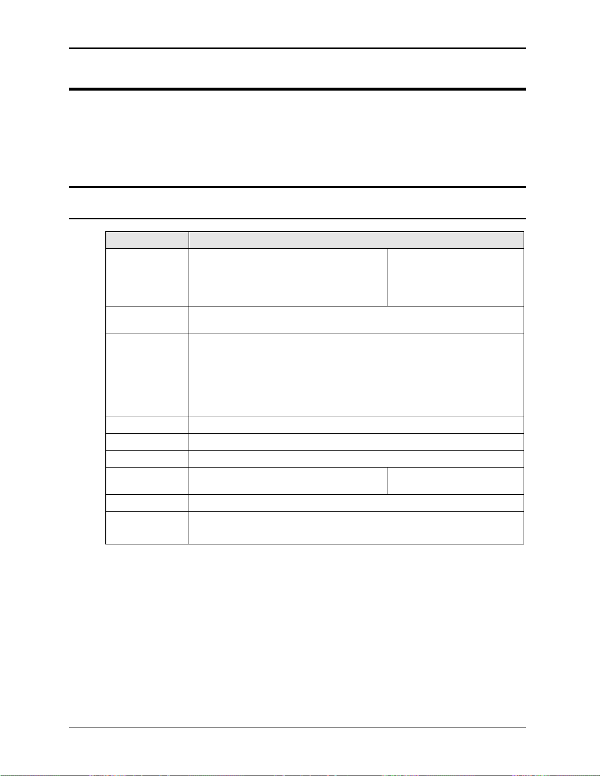
2.1 Electrical
2.1.1 Input
Parameter Specification
Line Voltage:
(3 phase, 3 wire
+ ground (PE))
Standard: 208 VAC ± 10 %
Optional: 240 VAC ± 10%
380 VAC ± 10%
415 VAC ± 10%
480 VAC ± 10%
Note: Each FCS chassis requires its
own AC service.
Line VA:
(total)
Line Current:
(per phase)
Line Frequency: 47- 63 Hz
Efficiency: 85 % (typical) depending on line and load
Power Factor: 0.85 (typical)
Inrush Current: 250 Apk max. Note: Each FCS chassis
Hold-Up Time: > 10 ms
Isolation
Voltage:
24 KVA. at nominal input voltage.
65 Arms @ 208 VAC
56 Arms @ 240 VAC
36 Arms @ 380 VAC
33 Arms @ 415 VAC
28 Arms @ 480 VAC
Currents shown are for single chassis models and per phase. For multichassis configurations, currents are per chassis.
requires its own AC service.
400 VAC RMS input to output
1350 VAC input to chassis
California Instruments 12
User Manual – Rev B FCS Series II
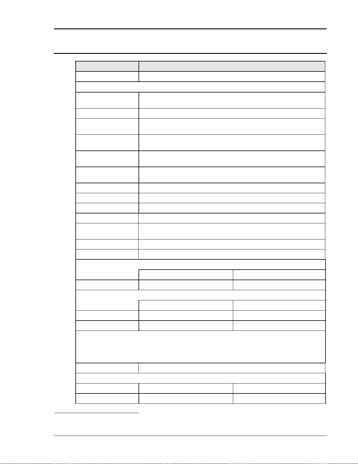
2.1.2 Output
Output Parameter Specification
Modes
AC
Voltage:
Standard Voltage
Ranges (L-N):
Low range: 0 – 135 Vac
High range: 0 – 270 Vac
Resolution: 0.1 V
Programming
Accuracy:
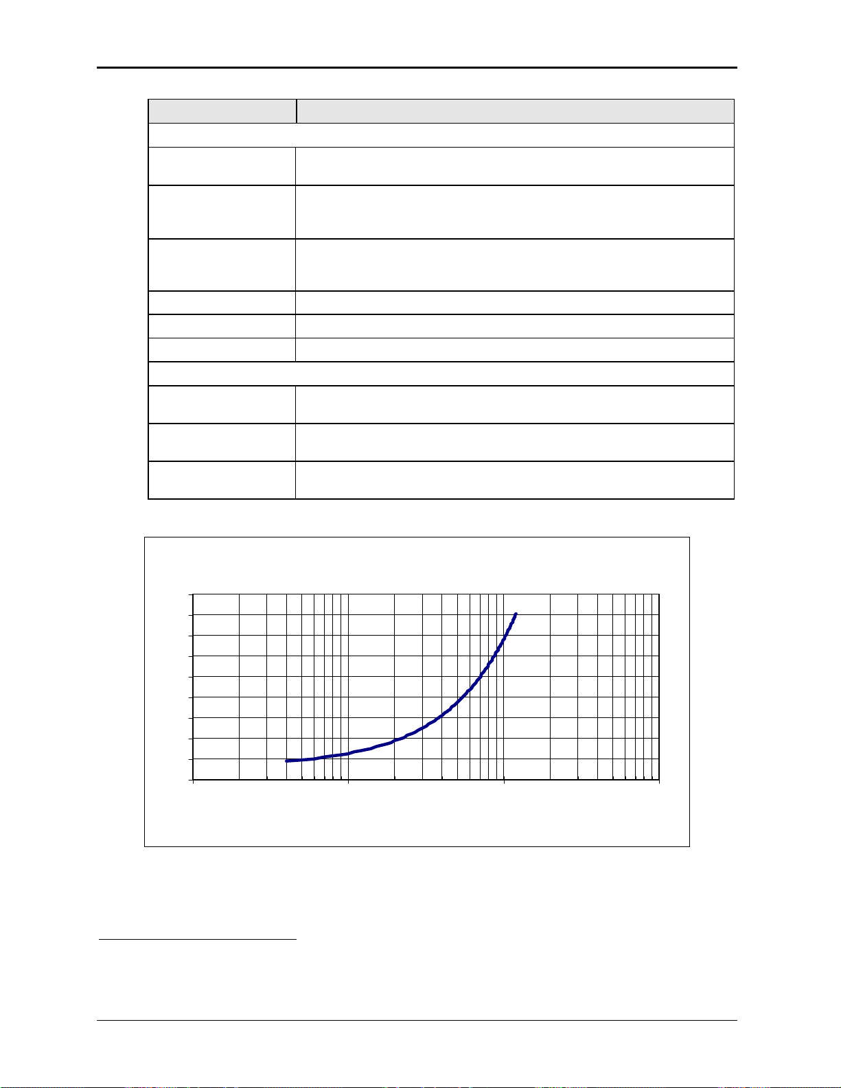
Distortion THD (to 80
1
Khz)
:
Load Regulation:
Specified at voltage sense point with ALC mode ON.
± (0.05% + 0.25 V) from 10V to FS.
< 1 % from 50 Hz to 60 Hz.
See for distortion as a function of frequency.
0.1 % FS
ALC mode ON
External Sense Up to 2% of Full scale voltage can be dropped across each load lead Internal
or External sense selectable.
Line Regulation: 0.1% for 10% input line change
Stability: ± 0.05% FS, 24 hours, constant line, load and temperature, ALC on.
Temp Coefficient: ± 0.05 V/°C
DC Offset Voltage: 0.0 V
Output Noise:
(20 kHz to 1 MHz)
Low voltage range: < 425 mV
High voltage range: < 950 mV
RMS
RMS
Output Coupling Transformer coupled
Output Impedance (Z) Z = Vrange * 0.001 / I_load
Power (total power per phase, either range, at full scale voltage)
FCS18-1 (single phase) FCS18-3 (three phase)
At 35° C ambient max. 18 kVA 6 kVA
Current
Model FCS18-1 (single phase) FCS18-3 (three phase)
135 V Range. 133.2 Arms 44.4 Arms
270 V Range. 66.6 Arms 22.2 Arms
Note: Current derates linearly from 50% of voltage range to 10% of specified current at 10% of
voltage range. See
Figure 2-2 for specified current versus voltage operating range.
Note: Current, maximum amps per phase available. For FCS36/2, currents are times two. For
FCS54/3, currents are times three. 35° C ambient max.
Current Limit mode Programmable, CC or CV mode
Repetitive Peak Current
135 V Range. 375 Apk 125 Apk
270 V Range. 187.5 Apk 62.5 Apk
1
The distortion specification for the FCS II Series applies at full-scale voltage, full resistive load conditions.
California Instruments 13
User Manual – Rev B FCS Series II
Output Parameter Specification
Frequency
Range: 45 Hz - 1200 Hz [Standard, -HV option]
45 Hz – 1000 Hz [-EHV option]
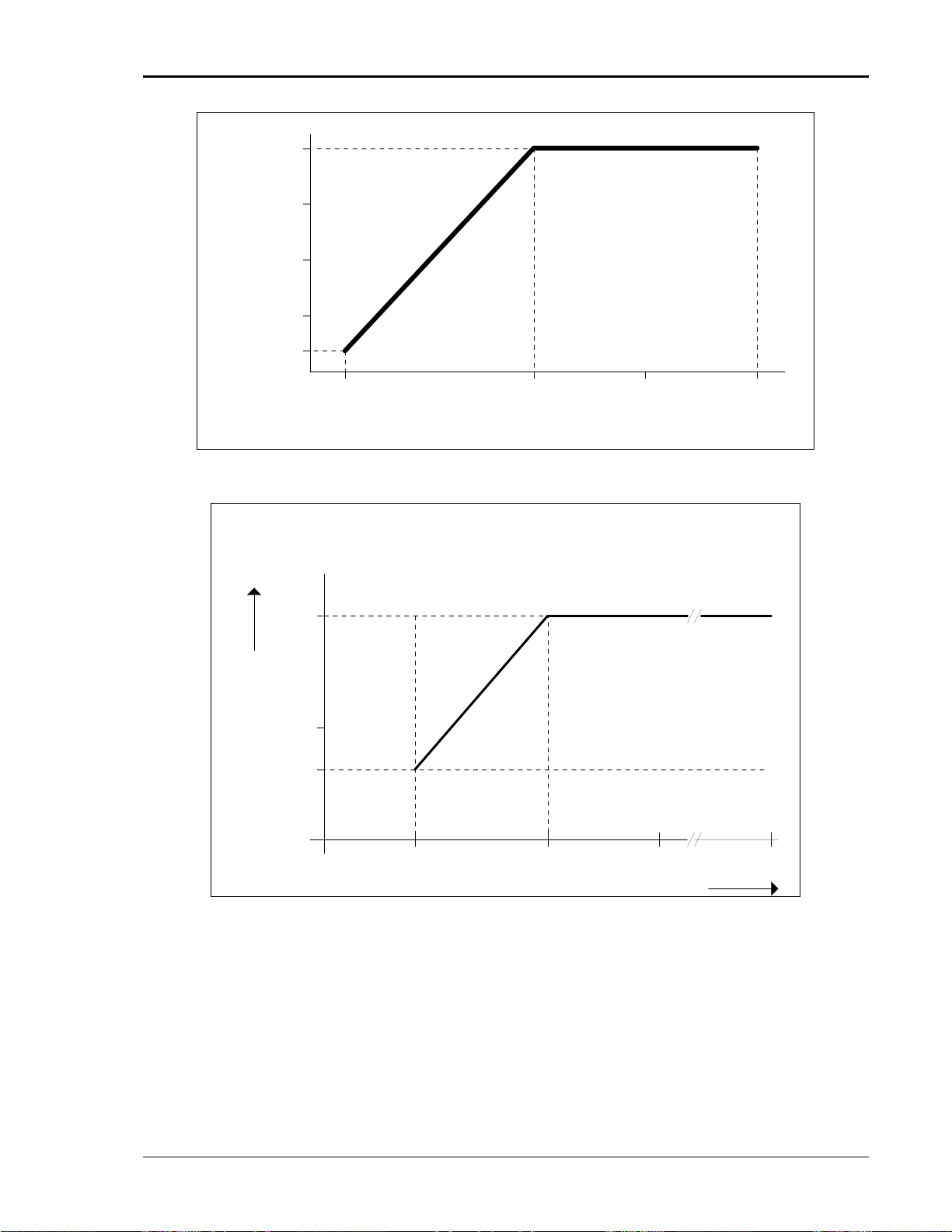
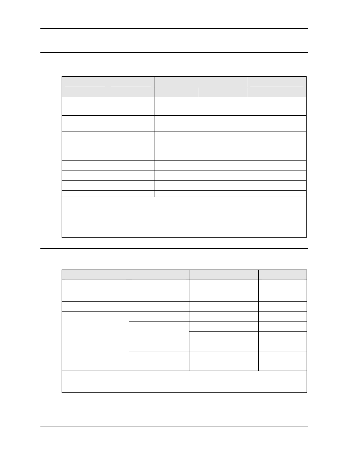
Supplemental Operation from 17 to 45 Hz is available at reduced output voltage.
Vout max = 100 % * F /45 for F < 45Hz. See chart
Voltage/Frequency rating.
Resolution1: 0.01 Hz [< 81.91 Hz]
0.1 Hz [> 82.0 to 819.1 Hz]
2
1 Hz
[> 819 Hz]
Accuracy: ± 0.025 %
Temp. Coefficient ± 5 ppm of value / °C
Stability: ± 15 ppm of value
Phase (3 phase mode)
Range: Phase B/C relative to phase A
0.0 to 360.0°
Resolution: 0.1° < 819.1 Hz
0.5° > 819.1 Hz
Figure 2-3 for
Accuracy: < 1° [45 Hz - 1000 Hz]
< 2 [1000 Hz – 1200 Hz]
Distortion (% THD)
4.50
4.00
3.50
3.00
2.50
2.00
1.50
1.00
0.50
0.00
10 100 1000 10000
Output Frequency
Figure 2-1: Distortion as a function of Output Frequency
1
Programming resolution reduced if –LKM/-LKS option is installed. See paragraphs 2.6.3.
2
Programming resolution of 0.5 Hz above 819.1 Hz may be used over the remote control bus with ± 0.5 Hz
accuracy.
California Instruments 14
User Manual – Rev B FCS Series II
)
100
S
F
%
(
T
75
N
E
R
R
U
50
C
T
U
P
T
U
O
25
10
10 50 75 100
OPERATING RANGE
OUTPUT VOLTAGE (% FS)
Figure 2-2: Current versus Voltage operating range.
Vout max.
in % FS
100%
50%
38%
17 Hz 45 Hz Max.
Frequency
Figure 2-3: Voltage / Frequency Rating
California Instruments 15
User Manual – Rev B FCS Series II
2.1.3 AC Measurements
Measurement specifications apply to single chassis FCS Series II AC source in three-phase
mode. See notes for other models and configurations.
Parameter Range
1 Phase Mode 3 Phase Mode
Frequency1 45.00-1200.0 Hz 0.1% ± 1 digit 0.01 Hz to 81.91 Hz
Phase
RMS Voltage 0 - 400 Volts 0.05% + 0.25V 0.01 Volt
RMS Current 0 - 150 Amps 0.1% + 0.45A 0.1% + 0.15A 0.001 Amp
Peak Current 0 - 250 Amps 0.2% + 1.5A 0.1% + 0.45A 0.001 Amp
Crest Factor 1.00 – 10.00 1.5 % 1.5 % 0.01
VA Power 0 - 6 KVA 0.3% + 15 VA 0.15% + 5 VA 1 VA
Real Power 0 - 6 KW 0.3% + 15 W 0.15% + 5 W 1 W
Power Factor 0.00 - 1.00 0.03 0.01 0.01
Note: Accuracy specifications are valid above 100 counts. For multi-chassis configurations, Current
and Power range and accuracy specifications are times the number of chassis.
Note: Frequency measurement specification valid for output > 20 Vrms.
Note: Crest Factor accuracy applies for Irms > 50% of max.
Note: Power Factor accuracy applies for PF > 0.5 and VA > 50% of max.
45.00 - 100.0 Hz
100.0 - 1200 Hz
2.1.4 Harmonic Measurements
Accuracy (±)
0.5°
2°
Resolution
0.1 Hz to 819.1 Hz
1 Hz > 819.1 Hz
0. 1°
Harmonic measurement specifications apply to FCS18-3 with –ADV option in three-phase
mode. See notes for single-phase mode or FCS18–1 with –ADV option.
Parameter Range
Frequency fundamental 45.00 - 81.91 Hz
82.0 - 819.1 Hz
> 819.1 Hz
Frequency harmonics 45.00 Hz – 16 kHz 0.1% + 2 digits 0.1 Hz
Voltage
Fundamental 0 - 400 Volts 0.05% + 0.25V 0.01V
Harmonic 2 - 50 0.1% + 0.1%/kHz + 0.25 0.01V
Current
Fundamental 0 - 20 Amps 0.1% + 0.15A 0.01A
Harmonic 2 - 50 0.1% + 0.1%/kHz + 0.05A 0.01A
Note: Current range and accuracy specifications are times three in single-phase mode. For multichassis configurations, current accuracy specifications are times the number of chassis. The harmonic
measurement bandwith increases to 48Khz in single-phase mode.
1
Frequency measurement specifications valid with output voltage of 30Vrms or higher. If output relay is open,
frequency measurement will return 0.0 Hz.
Accuracy (±)
0.1% ± 1 digit 0.01 Hz
Resolution
0.1 Hz
1 Hz
California Instruments 16
User Manual – Rev B FCS Series II
2.1.5 System Specification
Parameter Specification
Trigger Input: External trigger source input. Requires TTL level input signal. Triggers
on negative edge. Response time 80 - 100 µs.
Non volatile memory
storage:
Waveforms Standard: Sine
Transients Voltage: drop, step, sag, surge, sweep
Current Limit Modes: Two selectable modes of operation:
Interfaces
IEEE-488 AH1, DC1, DT1, L3, RL2, SH1, SR1, T6
LAN / Ethernet
(-LAN Option)
RS232C Baud rates, 9600, 19200, 38400, 57600 and 115200
16 complete instrument setups and transient lists, 100 events per list.
50 User defined waveforms.
with –ADV option: Sine, square, clipped, user defined
Frequency: step, sag, surge, sweep
Voltage and Frequency: step, sweep
1. Constant current mode (voltage folds back with automatic recovery)
2. Constant voltage mode with trip-off (Relays open).
IEEE 488.2 and SCPI
Response time is 10 ms (typical)
RJ45 Connector, 10BaseT, 100BaseT or 1000BaseT,
Data transfer rate: 460,800 bps
Protocol: TCP/IP.
Note: If –LAN is installed, RS232C interface is disabled.
Data bits: 8, Start bits: 1, Stop bits: 1, Parity: None
Syntax: SCPI
Response time is 10 ms (typical @ 115200 baud)
USB Standard USB peripheral.
2.1.6 Unit Protection
Parameter Specification
Input Over current: Input Circuit breaker. This breaker protects the equipment only and is not
Input Over voltage
Transients:
Output Over current: Adjustable level constant current mode with programmable set point.
Output Short Circuit: Peak and RMS current limit.
Over temperature: Automatic shutdown.
Data transfer rate: 460,800 bps
Syntax: SCPI
Note: Use of the USB port to control more than one power
source from a single PC is not recommended, as communication
may not be reliable. Use GPIB interface for multiple power source
control.
a branch protection device. AC input connection should be make using a
suitable branch protection device per local electrical code.
Surge protection to withstand EN50082-1 (IEC 801-4, 5) levels.
California Instruments 17
User Manual – Rev B FCS Series II
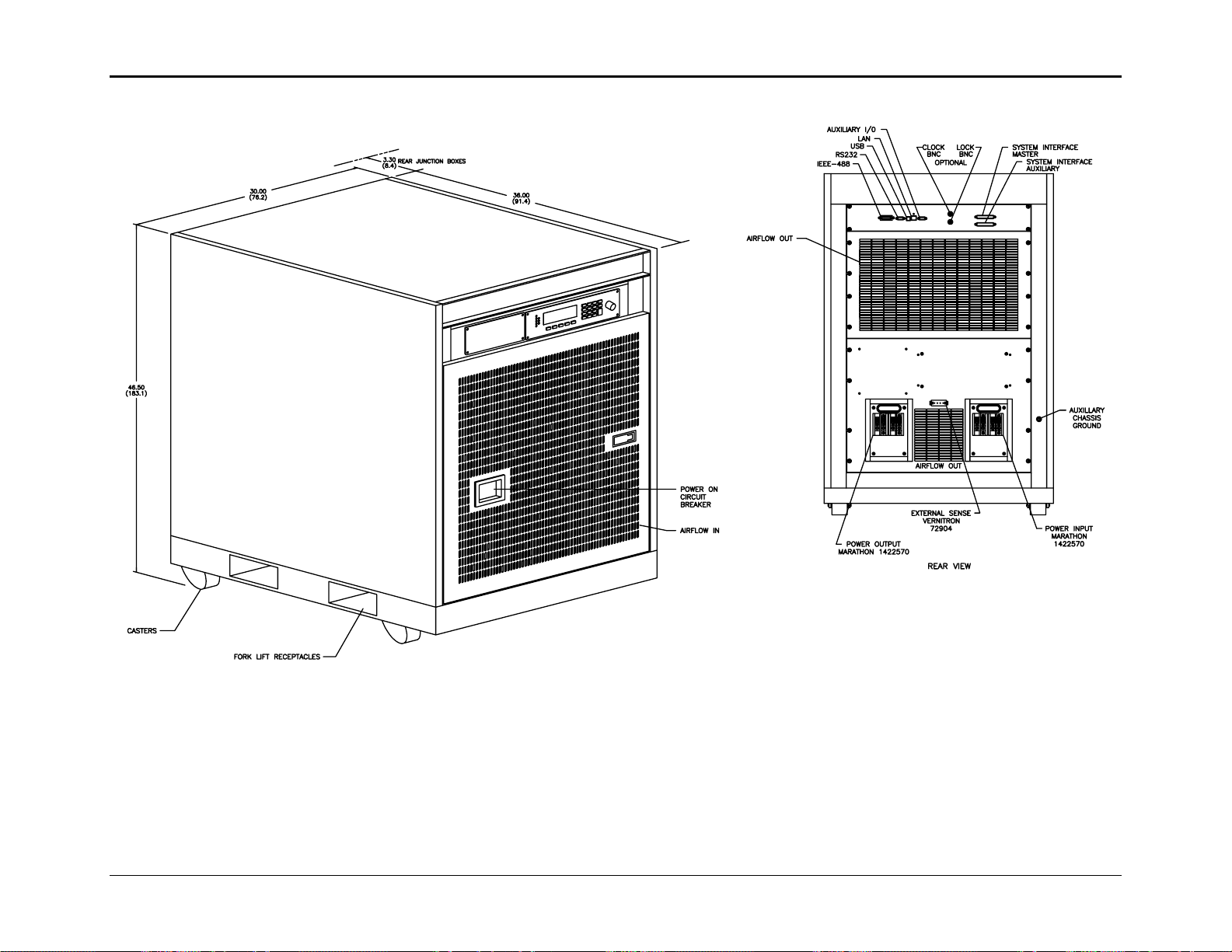
2.2 Mechanical
Parameter Specification
Dimensions: Floor standing Cabinet on casters:
Height: 45 inches (114.3 cm)
Depth: 36 inches + 4 inches for J-box = 40 inches (101.6 cm)
Width: 30 inches (76.2 cm)
All dimensions are per chassis. For /2 or /3 model configurations,
multiply height by 2 or 3 for total height.
Unit Weight:
Per chassis
Material: Steel chassis with steel side panels.
Finish: Powder coated.
Cooling: Fan cooled with front air intake and rear exhaust.
Acoustic Noise
(Supplemental
specification)
Internal Construction: Modular sub assemblies.
Rear Panel
Connections:
Net: 900 lbs / 87.7 Kg approximately
Shipping: 1100 lbs / 127.3 Kg
All weights are per chassis. For /2 or /3 model configurations, each
chassis is packaged individually.
Color: medium gray.
Variable speed fan control.
Measured at 1 m distance:
Fan speed: Low power mode Full power mode
Front of unit: 65 dBA 70 dBA
Rear of unit: 62 dBA 67 dBA
(See section 3 for description of connections)
• AC input wiring
• AC output wiring
• External sense terminal block (Remote voltage sense)
• System interface (2x)
• GPIB, USB, LAN (option) and RS232C
approximately
• Auxiliary I/O connector. (High density DB15)
2.3 Environmental
Parameter Specification
Operating Temp:
Storage Temp:
Altitude: < 2500 meters
Relative Humidity:
Indoor Use Only
California Instruments 18
0° to +35° C, full power, 0° to +50° C, reduced power
+32° to +95° F, full power, +32° to +122° F, reduced power.
-40° to +85 °C.
-40° to +185° F.
< 7500 feet
0-95 % RAH, non-condensing maximum for temperatures up to 31°C
decreasing linearly to 50% at 40°C.
User Manual – Rev B FCS Series II
Parameter Specification
Vibration: Designed to meet NSTA project 1A transportation levels using CI
provided packing crate.
Shock: Designed to meet NSTA project 1A transportation levels using CI
provided packing crate.
2.4 Front Panel Controls
Controls:
Shuttle knob: Shuttle knob may be used to adjust voltage, current limit and frequency
Numeric Keypad Keys 0 through 9, decimal point, and +/- sign key may be used to enter
Up/down arrow keys: A set of up and down arrow keys is used to move the cursor position in
Function keys:
Displays:
LCD graphics display: Large high contrast backlit LCD display. An adjustable viewing angle
Status indicators: Large and bright status indicators inform the user of important power
for selected phase or all three phases while in the SET menu. In all other
menu's, the shuttle may be used to change parameter values and
settings.
any numeric data value.
all menus. This allows quick selection of the desired function or
parameter.
Set key will show output voltage and frequency setting.
Meas key displays the measurement screens. Measure key will display
measurement values for selected phase or phase A if all three phases
are selected.
Menu key selects main menu.
Enter key is used to confirm selections.
Back key is used to back up to previous screen.
Output on/off key for output relay control.
Phase key toggles between phase A, B, C or all phases selection.
makes it easy to read from all practical locations.
source conditions.
The Remote lamp informs the user that the unit is under remote control.
The Overload lamp indicates that excessive current is being drawn at the
output.
The Over temperature lamp illuminates when internal heat sink
temperatures are too high.
The Hi Range indicator is lit any time the unit is switched to the high
voltage range.
The Output On/Off indicator is on when the power source output relays
are closed.
The Phase A, B and C indicators are lit when the relevant phase is
selected with the Phase key.
California Instruments 19
User Manual – Rev B FCS Series II
2.5 Special Features
Controller Features
Mode: Switches between 1 and 3 phase outputs.
Parallel Operation: FCS36 and FCS54 systems use two or three chassis in parallel
operation. The two or three chassis must be connected using the system
interface cable supplied with the system.
Controller: Programmable controller front panel assembly.
Output Relay: Standard output relay feature to isolate power source from the load.
Output On/Off: The output relay can be used to quickly disconnect the load. A yellow
status indicator displays the status of the output relay. Relay is either
through front panel button or using Remote Inhibit input signal.
External Trigger Output
or Function Strobe
Clock and Lock Mode Enables two or more independent FCS II power systems to be phase
Trigger Input A TTL input signal may be used as an external trigger source for output
An external TTL output is available which may be used to trigger other
equipment. The TTL output can be controlled by the transient
programming system. This requires the trigger mode to be set to EXT
(factory default). This can only be done over the bus using the
OUTP:TTLT:MODE TRIG command.
It can also be configured to generate an output pulse any time the
voltage, frequency, current limit or phase programming is updated. This
requires the trigger mode to be set to FSTR. This can only be done over
the bus using the OUTP:TTLT:MODE FSTR command. This mode is
compatible with the CI FCS Series I.
The Trigger Output / function strobe is an active low TTL signal with a
duration of no less than 400 usec.
synchronized to each other. One system (-LKM) acts as the master, the
other(s) (-LKS) as auxiliaries. The –LKS units are synced to the –LKM
unit. Refer to section 3.9 for details on Clock and Lock mode.
changes programmed on the AC power source transient system. This
requires the trigger source to be set to EXT. This can only be done over
the bus.
California Instruments 20
User Manual – Rev B FCS Series II
g
2.6 Available Options
AC Input Voltage Options
Line input: Must be specified at time of order. Refer to section 3.4.1
- 208 208V L-L AC nominal, 3 phase
- 240 240V L-L AC nominal, 3 phase
-380 380V L-L AC nominal, 3 phase
-415 415V L-L AC nominal, 3 phase
-480 480V L-L AC nominal, 3 phase
Output Options
- HV 156 / 312 V range output
- EHV 200 / 400 V range output
-LF Low frequency option. Limits maximum output frequency to 500 Hz.
-MODE Adds single phase and three-phase mode switching capability to FCS183 models. Not available on FCS18–1 or FCS36-3 and FCS54-3 models.
Firmware Options
Misc. Options
- 160 RTCA/DO-160D test firmware.
Includes RCTA-DO160D, section 16, Change #2 and EURO/CAE-14D
AC tests only.
- 704 Mil Std 704 test firmware – MIL704
Includes AC tests for Revisions D and E
- 704F Mil Std 704 test firmware – MS704
Includes AC tests for Revisions A through F
-ABD Airbus ABD0100.1.8 Tests. – ABD
Includes tables A, B and C.
This option can only be used with the provided LxGui Windows software.
-AMD Airbus AMD24C Tests. – AMD
Revision C.
This option can only be used with the provided LxGui Windows software.
-B787 Boeing 787B3-0147 Tests. – B787
This option can only be used with the provided LxGui Windows software.
-ADV Advanced features package. Adds arbitrary waveform generation and
harmonic analysis measurements.
-EXS External Sync (see Notes)
-LAN Ethernet LAN interface connection. RJ45 connector.
Note: When installed, RS232C interface is disabled.
-LKM Clock and Lock Master. Enables synchronizing outputs of two AC
sources, one acts as master.
This mode supports a frequency range of 45 to 819 Hz. See section 3.9.
-LKS Clock and Lock Auxiliary. See -LKM for details. (See Notes, see section
3.9.)
-MB Multi-box option. Provides additional controller(s) on FCS36/2 or FCS54/3
confi
urations allowing system to be separated into individual functional
California Instruments 21
User Manual – Rev B FCS Series II
units.
Notes: External Trigger input is standard.
External Trigger input and External sync are mutually exclusive.
Units with -LKS (auxiliary) cannot have External Sync.
2.6.1 -HV Option - Supplemental Specifications
Specifications for FCS units with -HV voltage range option installed are same as standard FCS
except where noted below.
Frequency
Range: 45 Hz - 1200 Hz
Voltage:
Ranges (L-N):
Low range 0 - 156 Vrms
High range 0 - 312 Vrms
Current
Model FCS18-1-HV (single p h ase) FCS18-3-HV (three phase)
156 V Range. 115.2 Arms 38.4 Arms
312 V Range. 57.6 Arms 19.22 Arms
Note: Current derates linearly from 50% of voltage range to 20% of specified current at 10% of
voltage range.
Note: Current, maximum amps per phase available. For FCS36/2, currents are times two. For
FCS54/3, currents are times three. 35° C ambient max.
Repetitive Peak Current
156 V Range. 325 Apk 108 Apk
312 V Range. 162 Apk 54 Apk
California Instruments 22
User Manual – Rev B FCS Series II
2.6.2 -EHV Option - Supplemental Specifications
Specifications for FCS units with -EHV voltage range option installed are same as standard FCS
unit except where noted below.
Frequency
Range: 45 Hz - 1000 Hz
Voltage:
Ranges (L-N):
Low range 0 - 200 Vrms
High range 0 - 400 Vrms
Current
Model FCS18-1-HV (single p h ase) FCS18-3-HV (three phase)
200 V Range. 90 Arms 30 Arms
400 V Range. 45 Arms 15 Arms
Note: Current derates linearly from 50% of voltage range to 20% of specified current at 10% of
voltage range.
Note: Current, maximum amps per phase available. For FCS36/2, currents are times two. For
FCS54/3, currents are times three. 35° C ambient max.
Repetitive Peak Current
200 V Range. 250 Apk 84 Apk
400 V Range. 125 Apk 42 Apk
California Instruments 23
User Manual – Rev B FCS Series II
2.6.3 -LKM and -LKS Options - Supplemental Specifications
The Clock and Lock option enables two independent FCS power systems to be phase synchronized to
each other. One system (-LKM) acts as the master, the other(s) (-LKS) as auxiliaries. The –LKS units are
synced to the –LKM unit. Refer to section 3.9 for details on Clock and Lock mode. Note that the maximum
number of auxiliary units (-LKS) per master (-LKM) is one. No T connectors are allowed to increase the
number of auxiliary units as this may cause reflections on the clock and lock signals.
Note: It is not possible to mix Series I FCS units and Series II FCS units in a clock and
lock configuration. Both models must be of the same series.
The following supplemental specifications apply when the Ls is configured with the Clock and Lock option.
(-LKM or –LKS).
Parameter Supplemental Specification
Voltage
Voltage Distortion Standard specifications apply.
Frequency
Range 45 – 1200 Hz (Standard, -HV)
45 – 1000 Hz (-EHV)
Resolution 0.1 Hz
Accuracy ± 0.025%
Phase
Phase Resolution Standard specifications apply.
Phase Accuracy Standard specifications apply.
California Instruments 24
User Manual – Rev B FCS Series II
2.6.4 –EXS Option - Supplemental Specifications
The –EXS (External Sync) option allows the output frequency of the AC source to be synchronized to an
external TTL level clock signal.
The following supplemental specifications apply when the FCS II is configured with the external sync option.
(-EXS).
Parameter Supplemental Specification
Input
Voltage Input TTL Level square wave.
Impedance 10 KOhm.
Frequency
Range Same as internal clock mode. See configuration limits.
Max Sync Input Slew Rate < 80 Hz / sec.
Changes in sync input frequency occurring faster than this rate will result in
Error 804: External Sync Error. Output relay is opened on Error.
Max Sync Step < 20 Hz.
Sudden changes in sync input frequency greater than 20 Hz will result in
Error 804: External Sync Error. Output relay is opened on Error.
Mode Selection
Restrictions
When switching between INT and EXT sync mode, the output of the AC
source will be dropped momentarily.
Frequency cannot be programmed in external sync mode.
Frequency transient list system is not available in sync mode.
Transient list dwell times are not correlated to external sync but based on
internal timebase.
California Instruments 25
User Manual – Rev B FCS Series II
3. Unpacking and Installation
3.1 Unpacking
Inspect the unit for any possible shipping damage immediately upon receipt. If damage is
evident, notify the carrier. DO NOT return an instrument to the factory without prior approval.
Do not destroy the packing container until the unit has been inspected for damage in shipment.
If possible, retain the container in the event the system ever has to be returned to the factory for
either repair of upgrades.
A forklift should be used to remove the FCS cabinet from its shipping crate. Once on a level
floor, the cabinet can be pushed in place using it’s own casters. Levelers at each corner may be
used to prevent the unit from moving. Levelers are not intended to support the entire weight of
the cabinet howewer.
. WARNING: This power source weighs approximately 900 lbs / 400 Kg per chassis
Obtain adequate help when moving or installing the unit. Make sure the floor on
es unit is installed can support the weight of the unit. which the FSC II Seri
3.2 Power Requirements
The FCS Series II power Source has been designed to operate from a three-phase, three wire
(Wye or Delta) AC input line. A protective earth connection is required as well. (PE).
Available three-phase input setting is 208 V
with optionally configured input settings. All three phase input is three wire plus
415 or 48
round.
g
CAUTION: Do not connect 400Vor 480V into a unit designed for 208V use. The result
0 V
LL
could be a severely damaged unit. Always check the input rating on the model
number tag before connecting AC input power. AC voltage input settings CANNO
be changed in the field. Contact CaT lifornia Instrument customer service to obtain
3.3 Mechanical Installation
The FCS II Series AC power sources can be used free standing on a solid surface. The units
are fan cooled, drawing air in from the front and exhausting at the rear. The back of each unit
must be kept clear of obstruction and a 6” clearance must be maintained to the rear. Spec
consideration of overall airflow characteristics and the resultant internal heat r
considered at all times to avoid self heating and over temperature problems.
Multi chassis configurations such as the FCS36/2 or FSC54/3 consist of two or three selfcontained FCS18 power sources. They must be connected through the system interface using
the supplied DB25 to DB25 cable. Output wiring from each chassis to th
wire gage and length to ensure proper current sharing between units.
Note that for multi-chassis systems, it is recommended to turn the Master unit ON first and th
the Auxiliary
Master unit.
unit(s). To turn the system off, turn OFF the Auxiliary unit(s) first and then the
nominal for standard FCS18 models or 230, 380,
LL
figuration. support for input recon
ial
ise must be
e EUT must be of equal
en
California Instruments 26

User Manual – Rev B FCS Series II
California Instruments 27
User Manual – Rev B FCS Series II
Figure 3-1: Rear Panel Connector Locations
California Instruments 28
User Manual – Rev B FCS Series II
3.4 AC Input Wiring – TB1
AC input connections are to be made directly to the input terminal block (TB1) of all units that
make up an FCS system. The input block is located on the lower right hand corner of the back
of the FCS18 chassis when facing the back. It is labeled “TB1” and “INPUT”. To connect AC
input wiring, remove the safety cover from the input junction box using a screwdriver to gain
access to the terminal block.
A Ground (earth) wire must be connected to the chassis of the AC power system using the
ground connection of the AC input connecter block. The mains source must have a current
rating equal to or greater than the input circuit breaker and the input wiring must be sized to
satisfy the cable elect qualified ele r to installati . Note
that all e size he worst-case maximum current that may occur
under low line conditions. ay also require different wire types and sizes.
Cable lengths must not exceed twenty-five (25) feet. For lengths greater than 25 feet, calculate
the vol m the f
2 X DISTANCE X CABLE RESISTANCE PER FT. X CURRENT = VOLT DROP
CAUTION: Capacitors in the power source may hold a hazardous electrical charge
appli rical codes. Consult a ctrician prio on
wires must b d to accommodate t
Local electrical codes m
tage drop fro ollowing formula:
even if the power source has been disconnected from the mains supply. Allow
capacitors to discharge to a safe voltage before touching exposed pins of mains
supply connectors. Power modules need at least 10 Minutes to discharge to safe
levels before they can be removed.
California Instruments 29

User Manual – Rev B FCS Series II
3.4.1 AC Input Voltage Taps
The factory configured input voltage is shown in the serial tag label at the back of the power
source cabinet. If it is required to change the factory set input voltage configuration, a new EMI
filter and circuit breaker may have to be installed depending on what filter and breaker was
originally installed. Refer to the table below for input wiring configuration settings and EMI filter
and CB part numbers.
NOMINAL INPUT
VOLTAGE
208
(187 - 229)
240
(216 - 264)
380
(342 - 418)
415 Jumper 1, 23
(374 - 456) Jumper 3, 5
480
(432 - 528)
TRANSFORMER
CONNECTIONS
Jumper 1, 5, 19, 23
Jumper 3, 7, 9, 13
Jumper 11, 15, 17, 21
Jumper 1, 5, 20, 24
Jumper 4, 8, 9, 13
Jumper 12, 16, 17, 21
Jumper 1, 22
Jumper 2, 5
Jumper 6, 9
Jumper 10, 13
Jumper 14, 17
Jumper 18, 21
Jumper 7, 9
Jumper 11, 13
Jumper 15, 17
Jumper 19, 21
Jumper 1, 24
Jumper 4, 5
Jumper 8, 9
Jumper 12, 13
Jumper 16, 17
Jump
er 20, 21
CIRCUIT
BREAKER
EMI FILTER
100 amp
270162
100 amp
270162
50 amp
270175
50 am
p
270175
50 amp
270175
250558
250558
250567
250567
250567
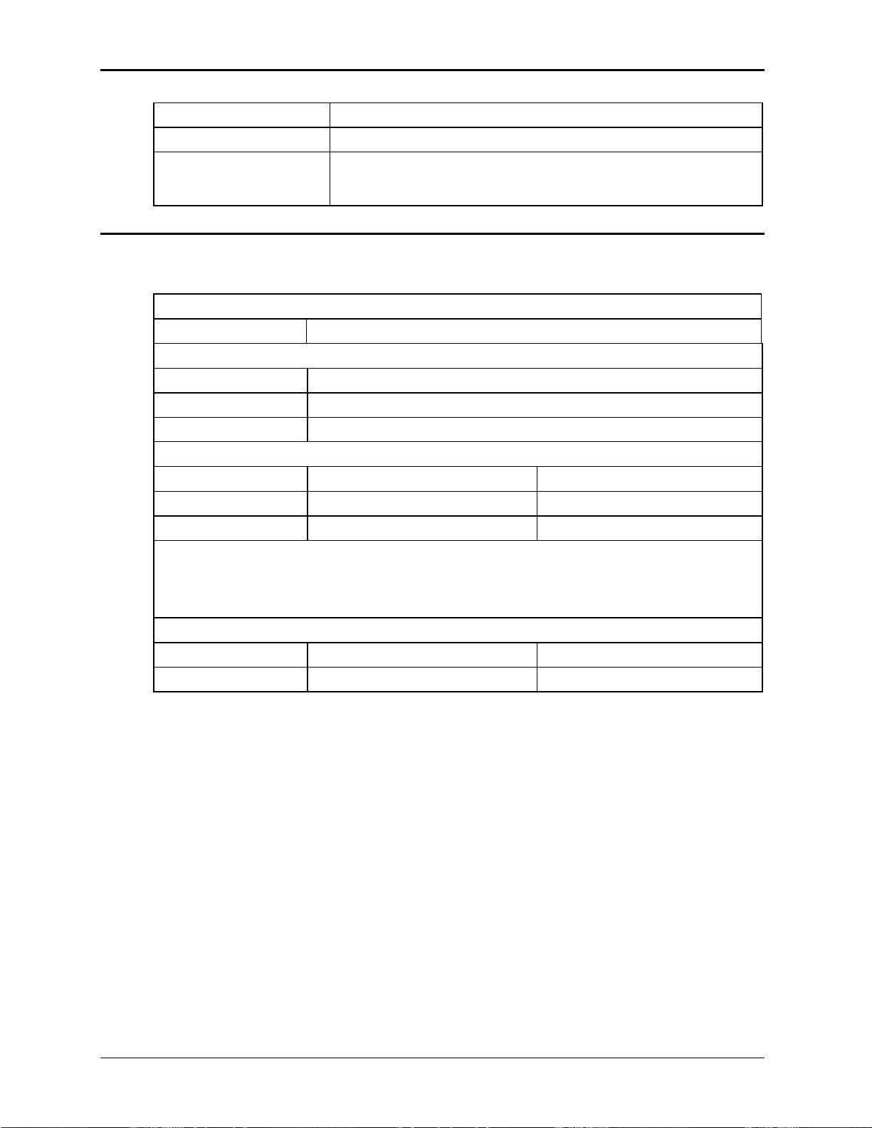
Table 3-1: AC Input transformer, EMI Filter and CB configurations.
Note: For 220V or 230V nominal input voltages, use the 240V nominal input tap setting.
California Instruments 30
 Loading...