

California Instruments 801RP Series, 1251RP Series User And Programming Manual

Revision P
October 2005
by California Instruments.
All rights reserved.
Copyright 1997-2005
P/N 5003-960
801RP / 1251RP Series AC Power
Source
User and Programming Manual
TEL: +1 (858) 677-9040
FAX: +1 (858) 677-0940
Email:
Web Site:
sales@calinst.com
http://www.calinst.com

User and Programming Manual - Rev P California Instruments
User's Manual
AC Power Source
California Instruments
Models :
801RP
1251RP
Copyright 1997 – 2005 California Instruments, Rev P, October 2005
RP Series October 2005 i

User and Programming Manual - Rev P California Instruments
SAFETY SUMMARY
This power source contains high voltage and current circuits which are potentially lethal.
Because of its size and weight, electrical and mechanical stability must be ensured. The
following safety guidelines must be followed when operating or servicing this equipment.
These guidelines are not a substitute for vigilance and common sense. California
Instruments assumes no liability for the customer's failure to comply with these
requirements.
APPLYING POWER AND GROUNDING
Verify the correct voltage is applied to the unit (100 to 240 VAC Nominal). Verify that the input power
cord is plugged into a properly grounded utility outlet.
FUSES
Use only fuses of the specified current, voltage, and protection speed.
Do not short out the fuse holder or use a repaired fuse.
The 801RP/1251RP unit uses a North American ferrule type fuse rated at 15A and 250Volts.
(Fast Acting)
DO NOT OPERATE IN A VOLATILE ATMOSPHERE
Do not operate the power source in the presence of flammable gases or fumes. This product is
designed to operate in a controlled environment. Do no expose to rain or snow.
DO NOT TOUCH ENERGIZED CIRCUITS
Disconnect the power cable before servicing this equipment. Even with the power cable
disconnected, high voltage can still exist on some circuits. Discharge these voltages before
servicing. Only qualified service personnel may remove covers, replace components or make
adjustments.
DO NOT SERVICE ALONE
Do not remove covers, replace components, or make adjustments unless another person, who
can administer first aid, is present.
DO NOT EXCEED INPUT RATINGS
Do not exceed the rated input voltage or frequency. Additional hazards may be introduced
because of component failure or improper operation.
DO NOT MODIFY INSTRUMENT OR SUBSTITUTE PARTS
Do not modify this instrument or substitute parts. Additional hazards may be introduced because
of component failure or improper operation.
MOVING THE POWER SOURCE
When moving the power source, observe the following:
1. Remove all AC power to unit.
2. Use two people to prevent injury.
SURFACE STABILITY
1. Operate the power source only on a level surface.
ii October 2005 RP Series

User and Programming Manual – Rev P California Instruments
WARRANTY INFORMATION
CALIFORNIA INSTRUMENTS CORPORATION warrants each instrument manufactured by them to
be free from defects in material and workmanship for a period of one year from the date of shipment to
the original purchaser. Excepted from this warranty are fuses and batteries that carry the warranty of
their original manufacturer where applicable. CALIFORNIA INSTRUMENTS will service, replace, or
adjust any defective part or parts, free of charge, when the instrument is returned freight prepaid, and
when examination reveals that the fault has not occurred because of misuse, abnormal conditions of
operation, user modification, or attempted user repair. Equipment repaired beyond the effective date
of warranty or when abnormal usage has occurred will be charged at applicable rates. CALIFORNIA
INSTRUMENTS will submit an estimate for such charges before commencing repair, if so requested.
SERVICE PROCEDURE
If a fault develops, notify CALIFORNIA INSTRUMENTS at support@calinst.com or its local
representative, giving full details of the difficulty, including the model number and serial number. On
receipt of this information, service information or a Return Material Authorization (RMA) number will be
given. Add the RMA number furnished to the shipping label. Pack the instrument carefully to prevent
transportation damage, affix label to shipping container, and ship freight prepaid to the factory.
CALIFORNIA INSTRUMENTS shall not be responsible for repair of damage due to improper handling
or packing. Instruments returned without RMA No. or freight collect
Instruments discretion. Instruments repaired under Warranty will be returned either via prepaid surface
freight or low cost airfreight at California Instruments discretion. Instruments repaired outside the
Warranty period will be returned freight collect, Ex Works CALIFORNIA INSTRUMENTS 9689 Towne
Centre Drive, San Diego, CA 92121-1964. If requested, an estimate of repair charges will be made
before work begins on repairs not covered by the Warranty.
may be refused at California
DAMAGE IN TRANSIT
The instrument should be tested when it is received. If it fails to operate properly, or is damaged in
any way, a claim should be filed immediately with the carrier. The claim agent should obtain a full
report of the damage, and a copy of this report should be forwarded to us by fax or email (Fax: 858
677 0940, Email:
repair cost and repair the instrument when authorized by the claim agent. Please include model
number and serial number when referring to the instrument.
support@calinst.com). CALIFORNIA INSTRUMENTS will prepare an estimate of
SPARE PARTS
To order spare parts, user manuals, or determine the correct replacement part for your California
Instruments products, please contact the Customer Service department by phone at + 1 858 677 9040,
press 2 or by email
support@calinst.com.
RP Series October 2005 iii

User and Programming Manual - Rev P California Instruments
Table of Contents
Introduction................................................................................................................................. 1
1.
1.1. General Description...................................................................................................................................1
2. Specifications.............................................................................................................................2
2.1. Electrical....................................................................................................................................................2
2.2. Mechanical................................................................................................................................................5
2.3. Environmental ........................................................................................................................................... 6
2.4. Regulatory.................................................................................................................................................6
2.5. Front Panel Controls .................................................................................................................................7
2.6. Available Options ......................................................................................................................................7
3. Unpacking and Installation.........................................................................................................8
3.1. Unpacking................................................................................................................................................. 8
3.2. Power Requirements ................................................................................................................................. 8
3.3. Mechanical Installation..............................................................................................................................8
3.4. Input Wiring...............................................................................................................................................9
3.5. Output Connections...................................................................................................................................9
3.6. Output Voltage Ranges...........................................................................................................................10
3.7. Functional Test........................................................................................................................................ 10
4. Front Panel Operation..............................................................................................................12
4.1. Front Panel Guided Tour.........................................................................................................................12
4.2. How to.....................................................................................................................................................16
5. Principle of Operation............................................................................................................... 19
5.1. General ...................................................................................................................................................19
5.2. Overall Description..................................................................................................................................19
5.3. Power Factor Correction Module (PFC).................................................................................................. 19
5.4. DC - DC Converter Module..................................................................................................................... 20
5.5. 20
5.6. Oscillator Control Board.......................................................................................................................... 21
5.7. DC to AC Power Module......................................................................................................................... 22
5.8. IEEE 488/ RS232....................................................................................................................................22
6. Calibration................................................................................................................................ 24
6.1. Calibration Equipment.............................................................................................................................24
6.2. Routine Calibration.................................................................................................................................. 24
6.3. Non-Routine Calibration..........................................................................................................................27
7. Service ..................................................................................................................................... 29
7.1. General ...................................................................................................................................................29
7.2. Basic Operation....................................................................................................................................... 29
7.3. Advanced Troubleshooting...................................................................................................................... 31
8. Introduction to PGUI32............................................................................................................. 34
8.1. About This Program ................................................................................................................................34
8.2. About This Section of the Manual ........................................................................................................... 34
8.3. Program Requirements........................................................................................................................... 34
8.4. RS232C Cable Wiring............................................................................................................................. 35
9. PGUI32 Setup and Installation.................................................................................................36
9.1. Connecting the AC Source to the PC When Using RS232...................................................................... 36
9.2. Connecting the AC Source to the PC Using IEEE-488............................................................................ 36
9.3. Installing the PGUI32 Software ............................................................................................................... 36
9.4. Trouble Shooting - RS232C ....................................................................................................................37
9.5. Registration.............................................................................................................................................39
iv October 2005 RP Series

User and Programming Manual – Rev P California Instruments
10. Top Assembly Replaceable Parts............................................................................................40
11. Programming Information.........................................................................................................41
12. Introduction to SCPI.................................................................................................................43
12.1. Conventions Used in This Manual...........................................................................................................43
12.2. The SCPI Commands and Messages......................................................................................................43
12.3. Using Queries..........................................................................................................................................45
12.4. Structure of a SCPI Message..................................................................................................................46
12.5. SCPI Data Formats..................................................................................................................................48
13. System Considerations ............................................................................................................50
13.1. IEEE Interface .........................................................................................................................................50
13.2. RS232C Interface....................................................................................................................................50
14. SCPI Command Reference...................................................................................................... 53
14.1. Introduction..............................................................................................................................................53
14.2. Subsystem Commands............................................................................................................................53
14.3. System Commands .................................................................................................................................60
14.4. Common Commands...............................................................................................................................63
15. Programming Examples...........................................................................................................69
15.1. Introduction..............................................................................................................................................69
15.2. Programming the Output .........................................................................................................................69
15.3. Making Measurements ............................................................................................................................70
16. Status Registers.......................................................................................................................71
16.1. Power-On Conditions...............................................................................................................................71
16.2. Standard Event Status Group..................................................................................................................72
16.3. Status Byte Register................................................................................................................................72
16.4. Examples.................................................................................................................................................73
17. Index.........................................................................................................................................77
RP Series October 2005 v

User and Programming Manual - Rev P California Instruments
List of Figures
Figure 3-1: The 801RP/1251RP AC Power Source .......................................................................................8
Figure 3-2: Rear Panel View..........................................................................................................................9
Figure 3-3: Functional test setup.................................................................................................................. 11
Figure 4-1: Front panel view ........................................................................................................................12
Figure 4-2: Shuttle Knob.............................................................................................................................. 14
Figure 5-1: AC Source block diagram.......................................................................................................... 19
Figure 5-2: Oscillator and controls ............................................................................................................... 21
Figure 6-1: Test Equipment Hookup for Routine Output Calibration............................................................ 25
Figure 6-2: Test Equipment Hook-up for Measurement Calibration............................................................. 26
Figure 6-3: Location of Internal Adjustments................................................................................................ 28
Figure 8-1: RS232C Cable Wiring................................................................................................................ 35
Figure 9-1: System Properties Dialog Box................................................................................................... 38
Figure 9-2: Advanced Port Settings Dialog Box...........................................................................................38
Figure 9-3: COM Port Properties Dialog Box............................................................................................... 39
Figure 12-1: Partial Command Tree............................................................................................................. 44
Figure 12-2: Command Message Structure................................................................................................. 46
Figure 13-1: GPIB Address Selection Switch.............................................................................................. 50
Figure 13-2: RS232C Interface cable wiring diagram................................................................................... 52
Figure 16-1: AC Source Status System Model............................................................................................. 71
List of Tables
Table 1: Logic Board LED's ......................................................................................................................... 20
Table 2: Load and current............................................................................................................................24
Table 3: Basic Symptoms ............................................................................................................................29
Table 4: Poor output voltage regulation .......................................................................................................29
Table 5: Overload Light On..........................................................................................................................29
Table 6: Distorted Output.............................................................................................................................30
Table 7: Unit shuts down after 3-5 seconds.................................................................................................30
Table 8: No output and no lights on front panel ........................................................................................... 30
Table 9: No output but "power on" led is lit...................................................................................................30
Table 10: Replaceable Parts........................................................................................................................40
Table 11: Bit configuration of standard event status enable register............................................................64
Table 12: Bit configuration of standard event status register ....................................................................... 65
Table 13: *RST default parameter values.................................................................................................... 67
Table 14: Status register power on condition...............................................................................................67
Table 15: Bit Configuration of Status Byte Register..................................................................................... 68
Table 16: Error Messages............................................................................................................................ 76
vi October 2005 RP Series

User and Programming Manual - Rev P California Instruments
1. Introduction
This instruction manual contains information on the installation, operation, calibration and
maintenance of the RP Series AC power source.
1.1. General Description
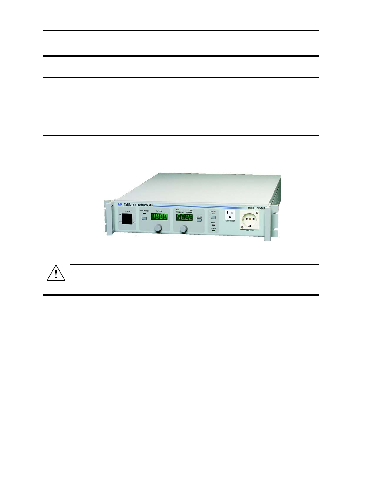
The 801RP/1251RP AC source is a high efficiency, light weight 800VA or 1250VA
programmable AC power source. The output has two voltage ranges of 0-135V or 0-270V
with a frequency range of 16 Hz to 500 Hz. The maximum output current for the 1251RP is
9.2 amps on 135 volts range and 4.6 amps on 270 volts range.
The maximum output current for the 801RP is 6 amps on 135 volt range and 3 amps on 270
volts range.
The universal nominal input can be from 100 volts to 240 volts at 50 Hz or 60 Hz line
frequency.
Simple front panel controls enable the voltage, current limit and frequency to be changed.
An optional RS232C and IEEE 488 interface is available for applications that require remote
control and measurements.
RP Series October 2005 1

User and Programming Manual - Rev P California Instruments
2. Specifications
All specifications at 25 5C unless noted otherwise.
2.1. Electrical
2.1.1. Input
Line Voltage: 85V to 264V maximum.
100V to 240V nominal.
Line Current: 15 A RMS max.
Line Frequency: 47-63 Hertz.
Efficiency: 80% (typical) depending on line and load.
Power Factor: 0.95 or greater typical.
Inrush Current: 70 A peak max. at 260V input.
Hold-Up Time: 20 ms (with no effect on output).
Isolation Voltage: Input to output = 2200 VAC, input to chassis = 1350 VAC.
2.1.2. Output
Voltage Range: 0 to 135 V rms or 270 V rms
Voltage Resolution: 0.1 volt
Voltage Accuracy: 1% of range, 50 to 60 Hz.
2% at 400 Hz
Line & Load Regulation: 1% of FS on low range, 0.5% of FS on high range.
Voltage Distortion: 0.5% typical. THD at 50/60 Hz.
Total Power: 800 VA maximum at full scale voltage, either range (Model
1250 VA maximum at full scale voltage either range (Model
801RP).
1251RP).
Note: On the 1251RP, the maximum output power is limited to 1000VA when the input
voltage is below 120VAC.
2
October 2005 RP Series

User and Programming Manual – Rev P California Instruments
Current: 6.0 A rms, 18 A peak (low range, Model 801RP)
3.0 A rms, 9 A peak (high range, Model 801RP)
9.2 A rms, 27.6 A peak (low range, Model 1251RP)
4.6 A rms, 13.8 A peak (high range, Model 1251RP)
Current Limit: 801RP
135V range: 0.0 to 6.0 9.2
270V range: 0.0 to 3.0 4.6
Accuracy: Programmed value +5% of maximum current
Frequency Range: Range Resolution
16.0 - 99.9 Hz 0.1 Hz
100 - 500 Hz 1 Hz
Frequency Accuracy: 0.02% of programmed value.
DC Offset Voltage: Less than 25 mV with linear load.
Output Noise: <0.2 volts RMS on 135 range, <0.5 volts RMS on 270 range.
2.1.3. Measurements
Current (TRMS)
1251RP
Resolution: 0.1 amp
Accuracy: 0.2 amp
Voltage Accessible only through RS232/ IEEE 488 Interface
0 - 250V 251 to 270V
Resolution 1 Volts 2 volts
Accuracy: 4 Volts 6 volts
RP Series October 2005
3

User and Programming Manual - Rev P California Instruments
2.1.4. System Specification
Non Volatile
Memory Storage: 8 complete instrument setups [ Accessible through RS232C interface
only ].
RS232C Interface: Bi-directional serial interface
[ optional ] 9 pin D-shell connector
Handshake: CTS, RTS
Data bits: 8
Stopbits: 1
Parity: None
Baud rate: 9600
IEEE 488.2 commands and SCPI
IEEE Interface: Bi-directional parallel interface
24 pin D-shell connection
IEEE address: set using DIP switch on rear panel from 0 to 31
IEEE functions: SH1, AH1, T8, L3, RL2
Terminators: LF, CRLF, EOI
IEEE 488.2 commands and SCPI
Remote Inhibit (Option –RI required)
Rear panel connector: BNC
Input Contact closure to ground or logic low TTL
signal required to turn off output.
Automatic recovery when RI signal is
removed.
4
October 2005 RP Series

User and Programming Manual – Rev P California Instruments
2.1.5. Unit protection
Input Overcurrent: Electronic current limit with fuse.
Input Overvoltage
Transients: Surge protection to withstand EN50082-1 (IEC 801-4, 5) levels.
Output Overcurrent: Shutdown, 0.1 second after overcurrent.
Output Overvoltage: Shutdown, recycle input power to reset.
Output Short Circuit: Peak current limit. Shutdown after 0.1 seconds.
Overtemperature: Automatic shutdown.
2.2. Mechanical
Dimensions: 16.51”(419.4mm) width x 3.5”(88.9 mm) height x 22”(558.8mm)
depth chassis size stand-alone configuration.
Unit Weight: 37 lbs.
Material: Aluminum chassis, panels and cover.
Finish: Yellow iridite then painted semi-gloss polyurethane
Cooling: Fan cooled with air intake on the sides and exhaust to the rear.
Internal Construction: Modular sub assemblies.
Chassis Slides: General Devices C300S-118-B308 (use hardware provided to
prevent damage to unit)
Front Panel Mounted
Output Connections:
CEE 7/7 European socket
US domestic Single 5-15R 120V line socket
Rear Panel Mounted
Connections:
RS232C Interface DB 9
IEEE-488 Interface D-shell 24 pin
Output Phoenix Contact HDFK4
Line Input IEC 320
RP Series October 2005
5

User and Programming Manual - Rev P California Instruments
2.3. Environmental
Operating Temp: 0 degrees to +40 degrees Celsius.
Storage Temp: -40 degrees to +85 degrees Celsius.
Humidity: Operating: 90% RH up to 40 C.
Storage: 90% RH up to 40 C, 75% RH up to 70 C.
Creepage and
Clearance: Rated for Pollution Degree 2.
Insulation: Rated to Installation Category (Overvoltage Category) II
Vibration: Designed to meet NSTA 1A transportation levels.
Shock: Designed to meet NSTA 1A transportation levels.
2.4. Regulatory
Electromagnetic Designed to meet EN50081-1 and EN50082-1 European Emissions
Emissions and and Immunity standards as required for the “CE” mark.
Immunity:
Acoustic Noise: 65 dBA maximum at 0% to 50% load, 75 dBA maximum greater than
50% load to 100% load. Measured at one meter.
Safety: Designed to meet UL3111 and EN61010-1 European safety
standards as required for the “CE” mark.
6
October 2005 RP Series

User and Programming Manual – Rev P California Instruments
2.5. Front Panel Controls
Controls: Shuttle knobs:
Allows continuous change of Voltage, Frequency and Current limit.
Function keys:
Controls Output state, Voltage range and Display mode.
1
Displays
Status Indicators:
6 LEDs to indicate:
REMOTE, FAULT, OUTPUT (ON/OFF), VOLTAGE RANGE,
: Two, 4 digits, 0.5” LED SEGMENT display. For viewing programmed
voltage, frequency, current limit and for displaying measured current.
FREQUENCY or CURRENT DISPLAY MODE (Refer to paragraph
4.1.2).
2.6. Available Options
The following options are available on 801RP and 1251RP AC power source models.
Option Description
-IF
-L22 Locking knobs. Prevents front panel change of voltage and
-RI Remote Inhibit rear panel input.
-RMS Rack mount slides
Combined IEEE-488 / RS232C interface option.
frequency.
P/N 210367
General Devices Model C300S-118-B308
1
801RP and 1251RP Series models shipped before Oct 2005 use LCD style displays instead of LED seven
segment displays. Other than the type of display used, there are no functional differences between both type
801RP and 1251RP Series models.
RP Series October 2005
7
User and Programming Manual - Rev P California Instruments
3. Unpacking and Installation
3.1. Unpacking
Inspect the unit for any possible shipping damage immediately upon receipt. If damage is
evident, notify the carrier. DO NOT return an instrument to the factory without prior
approval. Do not destroy the packing container until the unit has been inspected for damage
in shipment.
3.2. Power Requirements
The AC Power System has been designed to operate from a single phase AC line voltage.
The nominal operating voltage is from 100V to 240V line input.
Figure 3-1: The 801RP/1251RP AC Power Source
WARNING: Do not connect the unit to a 400-480 service as the result will be a
severely damaged unit.
3.3. Mechanical Installation
The AC Source is a completely self-contained power unit. It can be used free standing on a
bench. The unit is fan cooled, drawing air in from the sides and exhausting at the rear. The
sides of the unit must be kept clear of obstruction and a 4-inch clearance must be
maintained to the rear.
8
October 2005 RP Series
User and Programming Manual – Rev P California Instruments
3.4. Input Wiring
The AC Source is designed to work from a single utility supply. The IEC 320 input connector
will accept a standard IEC line cord with the appropriate mating connector for the utility
outlet. The utility outlet must be properly grounded and be capable of supplying at least 1725
VA at 120V to 240V in order to deliver full output power in the 1251RP.
Note: When using less than 120 V line input, the 1251RP should be used at no more
than 1000 VA output power to limit the input line current to less than 15A.
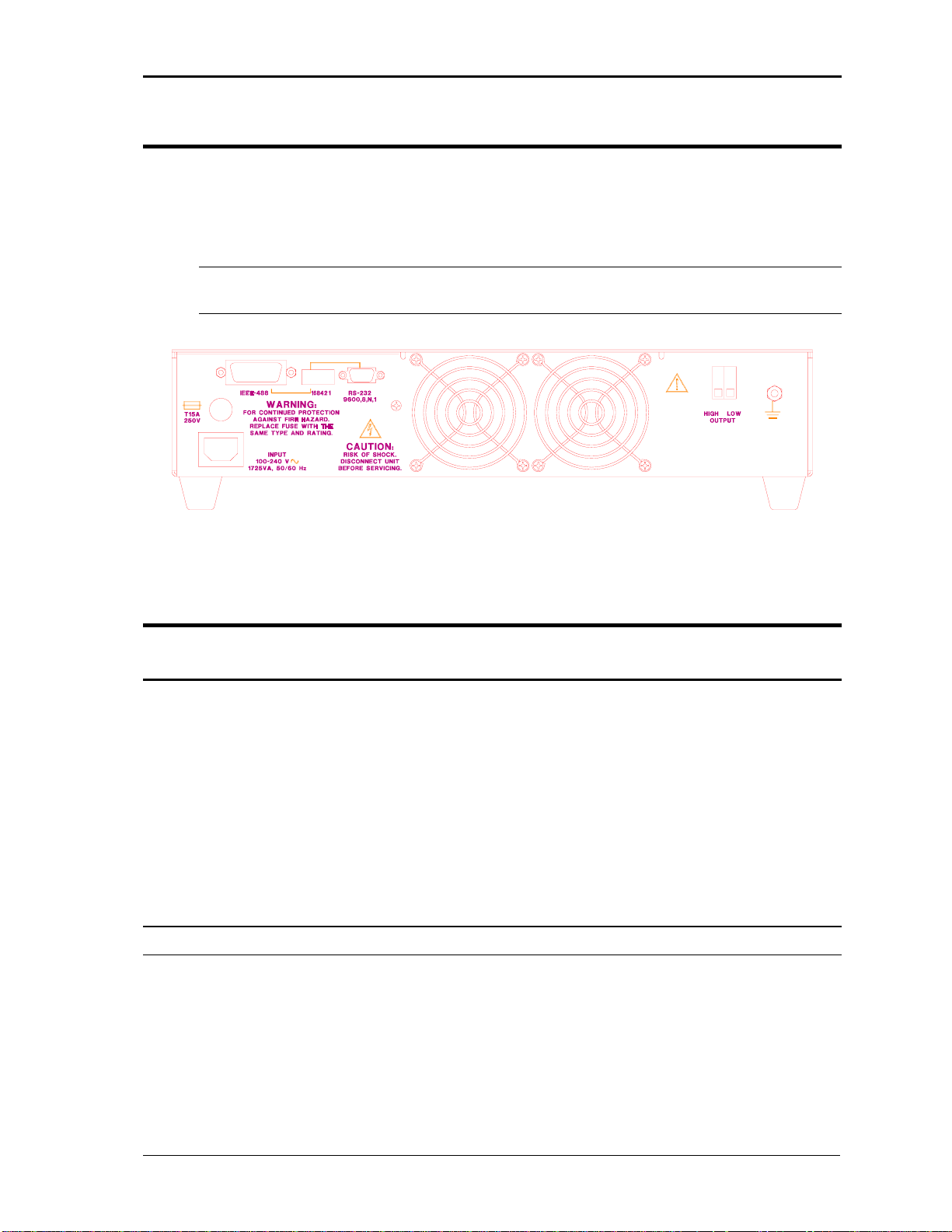
Figure 3-2: Rear Panel View
3.5. Output Connections
3.5.1. Output Wiring
Front Panel
When the low voltage range is selected, only the single US NEMA 5-15R output socket will
be active. If the high voltage range is selected, only the European CEE7/7 socket will be
active.
Either voltage will be present on the output terminals at the rear panel. There is only one
output terminal on the rear panel marked HIGH and LOW. This output carries the output of
the AC Source in both high and low voltage range. The HIGH and LOW label on the rear
panel refer to output high side and output low side (return) respectively, not to the voltage
range selected.
Note: Do not connect these outputs together as this will cause the unit to fault.
RP Series October 2005
9

User and Programming Manual - Rev P California Instruments
3.6. Output Voltage Ranges
The AC power source has two standard output voltage ranges 0-135V and 0-270V. The
operator may switch from one range to the other at will with no special precautions except to
remember that the output voltage will go to zero voltage whenever a range change takes
place.
Note: The output changes to the other socket on front panel with a range change.
3.7. Functional Test
CAUTION: Work carefully when performing these tests - hazardous voltages are
present on the input and output during this test.
Refer to Figure 3-3 for the test set up.
1. Connect an oscilloscope, voltmeter and/or distortion analyzer to the AC source output at
the 135 Volt output terminal.
2. Connect the AC power input voltage connections to the AC source input terminals. Turn
on the power switch located at the rear panel.
3. Verify that the front panel LED SEGMENT display reads out the initial start up voltage
and frequency.
4. Select the low voltage range. Set the frequency to 60 Hz with the right shuttle. Select the
current function with the Frequency/Current selector. Set the current limit to the
maximum value using the right shuttle. Set the output voltage to 135V with the left
shuttle.
5. Enable the output by pressing the output “on/off” button in the top right of the front panel.
The green LED above the button will illuminate when the output is on. The output
should be a clean 135 volt AC sinewave having less than 1% distortion.
6. Apply full load (refer to table on Figure 3-3) to the output of the source and verify the
output remains within 2% of the initial 135 volt value. The output should still be clean
and the distortion should still be less than 1% at 60 Hz.
7. Using the right shuttle set the output current limit value to 6 amps. The system should
go into current limit and give an error message on the display (err. -300) that indicates
an output fault condition and the output will go off. Return the current value to the
maximum current and disconnect the load.
8. Repeat steps 4 through 7 but set the output for the following: Hi voltage range and the
current limit to maximum value. The output load should be connected to the Hi range
output connector. The load value is shown in Figure 3-3, for the 270 volt output.
Note: Output connectors must be changed when changing voltage ranges unless
the rear panel output terminals are used.
10
October 2005 RP Series
User and Programming Manual – Rev P California Instruments
In the event the power source does not pass the functional test, refer to the calibration
procedure in Section 6 or call California Instrument’s customer satisfaction department for
further assistance.
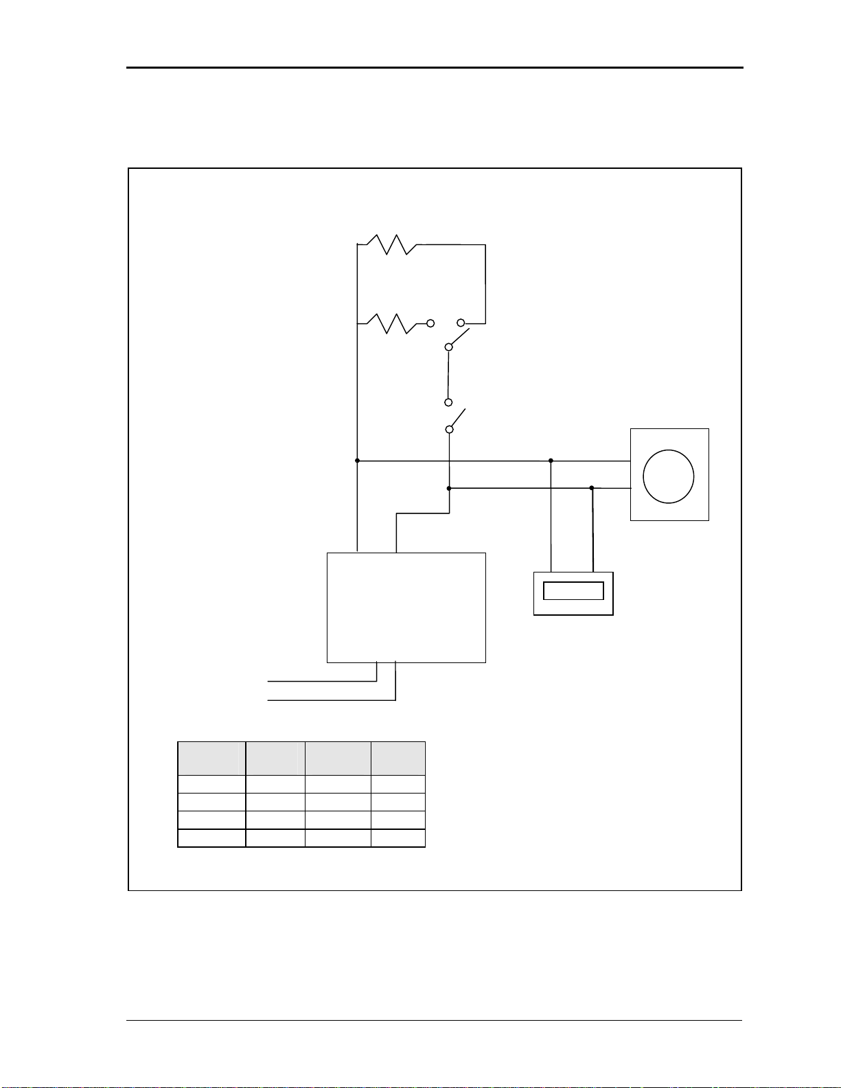
High Range Load
Low Range Load
Load ON/OFF Switch Oscilloscope
AC
Output
or Distortion
Analyzer
Unit
Under 270.0V
Test DMV
AC
Input
Model Range Current Load
801RP 135V 6.0A
801RP 270V 3.0A
1251RP 135V 9.2A
1251RP 270V 4.6A
22.5
90.0
14.6
58.6
Figure 3-3: Functional test setup
RP Series October 2005
11
User and Programming Manual - Rev P California Instruments
4. Front Panel Operation
4.1. Front Panel Guided Tour
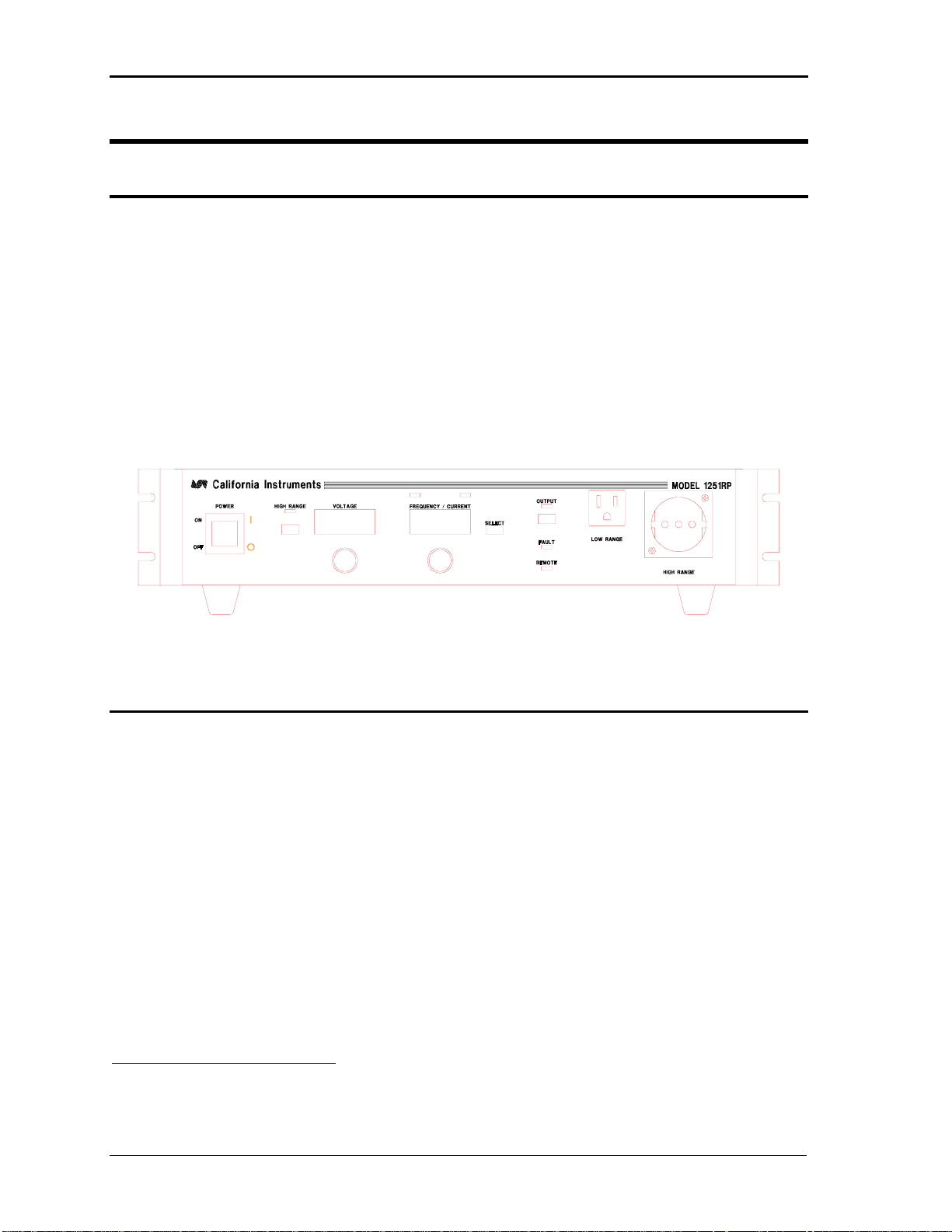
The front panel can be divided in a small number of functional areas:
Output Sockets
Status Indicator lights
Shuttle knobs
LED Segment Display
Button controls
4.1.1. Output Outlets
The Output Sockets are located on the right side of the front panel. It provides connection to
the load from the AC source. When the low voltage range is selected, only the US NEMA 515P output socket will be active. If the high voltage range is selected, only the European
CEE7/7 socket will be active. Refer to Figure 3-1 and Figure 4-1 for socket locations. Both
voltage ranges are present at the rear panel output terminals however. Refer to Figure 3-2.
1
Figure 4-1: Front panel view
1: 801RP and 1251RP Series models shipped before Oct 2005 use LCD style displays instead of LED seven
segment displays. Other than the type of display used, there are no functional differences between both type
801RP and 1251RP Series models.
12
October 2005 RP Series

User and Programming Manual – Rev P California Instruments
4.1.2. Status Indicator Lights
Six LED status indicators are located on the front panel. These LED’s correspond to the
following conditions:
REMOTE The REMOTE LED indicates that the unit is in remote
control mode. If the RS232C interface is used, the
REMOTE state can be enabled by the controller using the
SYST:REM command. Any time the REMOTE LED is lit,
the front panel of the RP Series unit is disabled. There is
no LOCAL button that allows the user to regain control of
the front panel. The SYST:LOC command will enable the
front panel controls. When using IEEE, the remote /local
state is controlled by the REN (Remote Enable) interface
line.
FAULT The FAULT LED indicates an output overvoltage or
overtemperature condition. Overtemperature is usually
caused by poor air flow. Check the air flow exhaust at the
rear of the unit to make sure it is not obstructed.
OUTPUT The Output LED indicates the status of the OUTPUT
ON/OFF button. When the Output LED is not lit, the output
voltage is not present at the output socket regardless of the
voltage setting.
RANGE The Range LED indicates the selected output voltage
range. When it is illuminated it indicates the high voltage
range has been programmed.
FREQUENCY Illuminates when the right hand side LED seven segment
display shows the programmed frequency.
CURRENT Illuminates when the right hand side LED seven segment
display shows the programmed current limit or measured
current values.
RP Series October 2005
13

User and Programming Manual - Rev P California Instruments
4.1.3. The Shuttle Knobs
Counter Clockwise
clockwise
DECREASE INCREASE
Figure 4-2: Shuttle Knob
There are two shuttle knobs located below the LED seven segment displays, which are used
to change setup parameters for voltage, frequency and current limit. The mode button
selects the function of the right shuttle. The right shuttle will control either the frequency or
the current limit as indicated by the indicator above the right LED segment display.
4.1.4. FUNCTION Buttons
There are three function buttons for the Output Voltage Range, Output State and Shuttle
Mode. The following is a description of these buttons:
KEY DESCRIPTION
RANGE The RANGE button is used to change the voltage range
OUTPUT The OUTPUT button will toggle the output to enable or
MODE The MODE button selects the function of the right shuttle
between the low range (0 to 135 volts) and high range (0 to
270 volts). The LED above the switch will light to indicate
the high voltage range selection. The output voltage will be
reset to zero voltage after a range change.
disable the output. The LED above the button will light
when the output is on. No output voltage will be present
when the OUTPUT button is off despite the level of voltage
programmed.
knob and the right LED segment display. The shuttle will
control the output frequency and the display will show the
program frequency value when the mode selection is
frequency. The Shuttle knob will program the current limit
and the display will show its value in the current mode. The
display will revert back to showing the measured current
after 3 seconds from the last movement of the shuttle. The
measurement is updated 4 times per second. The display
mode is indicated by the two LED’s above the LED segment
display.
14
October 2005 RP Series

User and Programming Manual – Rev P California Instruments
4.1.5. LED seven segment displays
The digital readouts consists of two 4 digit, LED seven segment displays1. The voltage
display shows the programmed voltage. The Frequency/Current display shows either the
programmed frequency or current limit. In the current limit mode the display switches to
display the output current after 3 seconds. The Frequency/Current select button will define
the operating mode of the frequency/current display.
1
801RP and 1251RP Series models shipped before Oct 2005 use LCD style displays instead of LED seven
segment displays. Other than the type of display used, there are no functional differences between both type
801RP and 1251RP Series models.
RP Series October 2005
15

User and Programming Manual - Rev P California Instruments
4.2. How to...
This chapter covers some common tasks that are often performed with an AC power source.
These examples are written in a How to... format and provide step by step instructions on
how to set up the AC Source for a specific task.
4.2.1. Set the Output
Output parameters are Voltage, Frequency and Current Limit.
1. Disable the output by pressing the OUTPUT button. The LED above the button will turn
off.
2. Use the left shuttle to set the output voltage. Clockwise will increase the output, counter
clockwise will reduce the output. The display above the shuttle will show the voltage
setting.
3. Use the right shuttle to set the frequency and current limit. The Frequency/Current select
button will define the function of the shuttle and the display above it. The Frequency or
Current LED will turn on to indicate the function controlled by the right shuttle.
4. Enable the output by pressing the OUTPUT button.
4.2.2. Slew ing Output Values
The output parameters can be slewed using the shuttles.
1. Enable the output by pressing the OUTPUT button. The LED above it will turn on.
2. Use the left shuttle to set the output voltage. Clockwise will increase the output,
counter clockwise will reduce the output. The display above the shuttle will show the
voltage setting.
3. Use the right shuttle to set the frequency and current limit. The Frequency/Current
button will define the function of the shuttle as indicated by the display above it. The
Frequency or Current LED will turn on to indicate the function in control.
4.2.3. View Current Measurements
Current measurements can be called up as follows:
1. Press the Frequency/Current button to select the Current function.
2. Immediately the Frequency/Current display will show the measured current.
3. Moving the right shuttle will interrupt the current measurement. The display will show
the current limit value.
4. After a short delay the display will revert back to show the measured current.
16
October 2005 RP Series

User and Programming Manual – Rev P California Instruments
4.2.4. Voltage Range Change
The voltage range can be changed as follows:
1. Press the HI RANGE button located in the upper left corner. The output voltage will
reset to 0 volts.
2. Use the left shuttle knob to set the output voltage.
4.2.5. Output Control
The Output can be disabled or enabled as follows:
1. Pressing the OUTPUT button when the output LED is on will disable the AC source
output. The programmed voltage setting will remain at the last program value.
2. Pressing the OUTPUT button again will enable the output voltage and the output will
revert to the last programmed value.
4.2.6. Setting the Pow er on Initialization Values
All P and RP series are supplied with default factory settings when the unit is powered up.
The factory settings are:
Voltage range Low
Voltage 0 V
Frequency 60 Hz
Current limit Max available current
Display mode Frequency
Output OFF
It is possible to change the power on initialization values in one of two ways:
1. Using the optional RS232 or IEEE-488 (RP only) interface and the supplied PGUI32
program.
2. Using the front panel. (requires main firmware release 1.0 or higher).
To change the power on initialization values from the front panel, proceed as follows:
1. Set the unit up in the desired way from the front. (Range, voltage, frequency, current
limit, output relay state). Note: The display mode – frequency or current – is not saved
as part of the set up and always defaults to frequency.
2. Press and hold the Select key (normally toggles between F and C readouts).
RP Series October 2005
17

User and Programming Manual - Rev P California Instruments
3. While holding the Select key, press the OUTPUT ON/OFF key. This will save the
present front panel settings in non volatile memory register (NVM) no 7 and assign this
register as the power on register.
4. Release both keys.
5. This procedure can be repeated as often as needed by the user.
18
October 2005 RP Series
User and Programming Manual – Rev P California Instruments
5. Principle of Operation
5.1. General
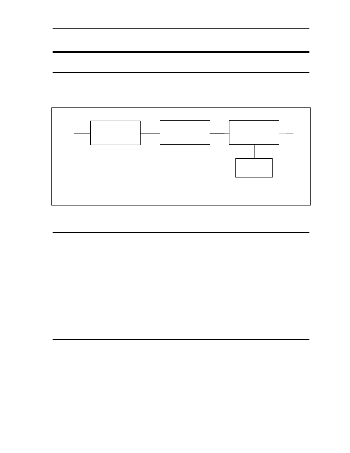
An explanation of the circuits in the AC Source is given in this section. Refer to Figure 5-1
for a block diagram of the system.
AC Power Factor DC - DC DC - AC AC
Input Corrector (PFC) Converter Converter Output
Oscillator &
Controls
Figure 5-1: AC Source block diagram
5.2. Overall Description
The AC input is fed to the power factor correction, boost type converter. The converter steps
the voltage to 385 VDC while drawing near sinusoidal current from the input power line.
The DC to DC converter provides isolation and changes the voltage to 250 VDC or 400 VDC
depending on whether the low output range or high output range is selected.
The DC to AC converter develops an AC sine wave voltage at the output frequency and
amplitude programmed by the oscillator.
The oscillator board provides the reference signal to the DC to AC converter and has the
front panel shuttles and switches to control and view the setting of voltage, frequency and
current limit.
5.3. Power Factor Correction Module (PFC)
The PFC consists of the boost converter circuitry. The boost converter is PWM controlled by
a single chip that adjusts the pulse width during the cycle so that near sine wave current is
drawn from the supply. An auxiliary winding on the boost inductor provides “bootstrap”
power to the logic circuits and is self sustaining.
RP Series October 2005
19
 Loading...