

California Instruments 2253iX User Manual

Revision E
June 2008
by California Instruments.
All rights reserved.
Copyright © 2007
P/N 6005-962
2253i / 2253iX
AC and DC Power Source
User Manual
TEL: +1 (858) 677-9040
FAX: +1 (858) 677-0940
Email:
Web Site: http://www.calinst.com
sales@calinst.com

User Manual 2253i / 2253iX
Refers to:
Models:
2253i AC and DC Power Source
2253iX AC and DC Power Source/Analyzer
Manual revision: E.
Copyright © 2007-2008 California Instruments Corporation.
California Instruments 2

User Manual 2253i / 2253iX
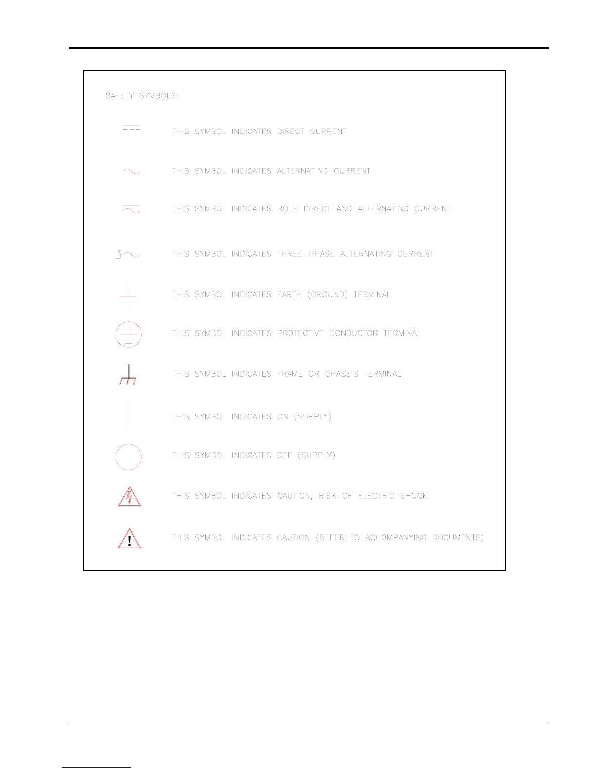
SAFETY SUMMARY
This power source contains high voltage and current circuits, which are potentially lethal. Because
of its weight, proper placement on a work surface or installation in a cabinet must be ensured. The
following safety guidelines must be followed when operating or servicing this equipment. These
guidelines are not a substitute for vigilance and common sense. California Instrumen ts assumes no
liability for the customer’s failure to comply with these requirements. If the power source is used in
a manner not specified by California Instruments, the protection provided by the equipment may be
impaired.
BEFORE APPLYING POWER
1. Verify the correct input voltage is applied to the unit. Allowable input ratings are shown on the model
and serial number tag located at the rear of the unit. The selected input voltage setting is visible on the
voltage selector slide switch on the rear panel of the unit.
2. The chassis and cabinet of this power source must be grounded to minimize shock hazard. A chassis
ground is provided at the input terminal block. This is located on the rear panel of the unit. The
chassis ground must be connected to an electrical ground through an insulated wire of sufficient
gauge.
FUSES
Use only fuses of the specified current, voltage, and protection speed (slow blow, normal blow, fast blow)
rating. Do not short out the fuse holder or use a repaired fuse.
DO NOT OPERATE IN A VOLATILE ATMOSPHERE
Do not operate the power source in the presence of flammable gases or fumes.
DO NOT TOUCH ENERGIZED CIRCUITS
Disconnect the power cable before servicing this equipment. Even with the power cable disconnected, high
voltage can still exist on some circuits. Discharge these voltages before servicing. Only qualified service
personnel may remove covers, replace components or make adjustments.
DO NOT SERVICE ALONE
Do not remove covers, replace components, or make adjustments unless another person, who can
administer first aid, is present.
DO NOT EXCEED INPUT RATINGS
Do not exceed the rated input voltage or frequency. Additional hazards may be introduced because of
component failure or improper operation.
DO NOT MODIFY INSTRUMENT OR SUBSTITUTE PARTS
Do not modify this instrument or substitute any parts. Additional hazards may be introduced because of
component failure or improper operation.
MOVING THE POWER SOURCE
When moving the power source, observe the following:
1. Remove all AC power to unit.
2. Do not carry unit using front panel handles. Handles are intended for pulling power source out of cabinet
only. Support unit at bottom when moving.
3. Do not lift alone. Two man lift recommended.
ALLOW CAPACITORS TO DISCHARGE
Capacitors in the power source may hold a hazardous electrical charge even if the power source has been
disconnected from the mains supply. Allow capacitors to discharge to a safe voltage before servicing internal
circuits or touching exposed pins of the mains supply connectors.
California Instruments 3
User Manual 2253i / 2253iX
California Instruments 4

User Manual 2253i / 2253iX
WARRANTY INFORMATION
CALIFORNIA INSTRUMENTS CORPORATION warrants each instrument manufactured by them to be free from
defects in material and workmanship for a period of one year from the date of shipment to the original purchaser.
Excepted from this warranty are fuses and batteries that carry the warranty of their original manufacturer where
applicable. CALIFORNIA INSTRUMENTS will service, replace, or adjust any defective part or parts, free of
charge, when the instrument is returned freight prepaid, and when examination reveals that the fault has not
occurred because of misuse, abnormal conditions of operation, user modification, or attempted user repair.
Equipment repaired beyond the effective date of warranty or when abnormal usage has occurred will be charged
at applicable rates. CALIFORNIA INSTRUMENTS will submit an estimate for such charges before commencing
repair, if so requested.
VOIDED WARRANTY
Any misuse or abuse of, as well as any modifications or changes made to any California Instruments product will
automatically void the factory warranty. Removing non-normal use related covers or any sealed covers or lids
also automatically voids factory warranty unless express written or email authorization is obtained from the
customer service department in advance. The customer service department can be reached via email at
support@calinst.com.
SERVICE PROCEDURE
If a fault develops, notify CALIFORNIA INSTRUMENTS at
full details of the difficulty, including the model number and serial number. On receipt of this information, service
information or a Return Material Authorization (RMA) number will be given. Add the RMA number furnished to the
shipping label. Pack the instrument carefully to prevent transportation damage, affix label to shipping container,
and ship freight prepaid to the factory. CALIFORNIA INSTRUMENTS shall not be responsible for repair of
damage due to improper handling or packing. Instruments returned without RMA No. or freight collect
refused at California Instruments discretion. Instruments repaired under Warranty will be returned either via
prepaid surface freight or low cost airfreight at California Instruments discretion. Instruments repaired outside the
Warranty period will be returned freight collect, Ex Works CALIFORNIA INSTRUMENTS 9689 Towne Centre
Drive, San Diego, CA 92121-1964. If requested, an estimate of repair charges will be made before work begins
on repairs not covered by the Warranty.
support@calinst.com or its local representative, giving
may be
DAMAGE IN TRANSIT
The instrument should be tested when it is received. If it fails to operate properly, or is damaged in any way, a
claim should be filed immediately with the carrier. The claim agent should obtain a full report of the damage, and
a copy of this report should be forwarded to us by fax or email (Fax: 858 677 0940, Email:
CALIFORNIA INSTRUMENTS will prepare an estimate of repair cost and repair the instrument when authorized
by the claim agent. Please include model number and serial number when referring to the instrument.
support@calinst.com).
SPARE PARTS
To order spare parts, user manuals, or determine the correct replacement part for your California Instruments
products, please contact the Customer Service department by phone at + 1 858 677 9040, press 2 or by email
support@calinst.com.
California Instruments 5

User Manual 2253i / 2253iX
Table of Contents
1. Introduction ................................................................................................................................................... 10
1.1 General Description...........................................................................................................................................10
1.2 iX and i Model Differences.................................................................................................................................11
1.3 Manual organization and format ........................................................................................................................11
2. Specifications ............................................................................................................................................... 12
2.1 Electrical............................................................................................................................................................12
2.2 Mechanical ........................................................................................................................................................ 22
2.3 Environmental ...................................................................................................................................................23
2.4 Front Panel Controls, Indicators and Display ....................................................................................................24
2.5 Special Features ...............................................................................................................................................25
2.6 Available Options – i Series...............................................................................................................................26
2.7 Available Options – iX Series ............................................................................................................................27
2.8 EXT Option - Supplemental Specifications........................................................................................................28
2.9 LKM / LKS Options - Supplemental Specifications............................................................................................30
2.10 RPF Option - Supplemental Specifications........................................................................................................30
2.11 WHM Option - Supplemental Specification........................................................................................................30
2.12 Supplemental Specifications .............................................................................................................................31
3. Unpacking and Installation ........................................................................................................................... 33
3.1 Unpacking .........................................................................................................................................................33
3.2 AC Input Power Requirements..........................................................................................................................33
3.3 Mechanical Installation ......................................................................................................................................33
3.4 Rear Panel Connectors .....................................................................................................................................35
3.5 AC Input Wiring - INPUT ...................................................................................................................................36
3.6 Output Connections...........................................................................................................................................37
3.7 Connectors - Rear Panel...................................................................................................................................39
3.8 Basic Initial Functional Test...............................................................................................................................45
3.9 Clock and Lock Mode (-LKM/-LKS Option)........................................................................................................47
3.10 Remote Control Interfaces ................................................................................................................................48
4. Front Panel Operation .................................................................................................................................. 49
4.1 Tour of the Front Panel .....................................................................................................................................49
4.2 Menu Structure..................................................................................................................................................54
4.3 Output Programming .........................................................................................................................................78
4.4 Waveform Management ....................................................................................................................................80
4.5 Measurements...................................................................................................................................................83
4.6 Harmonic Analysis.............................................................................................................................................84
4.7 Transient Programming.....................................................................................................................................84
4.8 Setting the Power-on Initialization Values .........................................................................................................89
4.9 Remote Inhibit Function ....................................................................................................................................90
5. Principle of Operation ................................................................................................................................... 91
5.1 Overall Description ............................................................................................................................................91
5.2 Amplifier Assemblies .........................................................................................................................................91
5.3 PFC and Rectifier Assembly..............................................................................................................................91
5.4 EMI Filter Assembly ..........................................................................................................................................91
5.5 Auxiliary DC bias Supply ...................................................................................................................................91
5.6 Range/Relay Assembly ..................................................................................................................................... 92
5.7 Interface Assembly............................................................................................................................................92
5.8 Front Panel Assembly .......................................................................................................................................92
California Instruments 6

User Manual 2253i / 2253iX
6. Calibration..................................................................................................................................................... 94
6.1 Recommended Calibration Equipment ..............................................................................................................94
6.2 Calibration Screens ...........................................................................................................................................94
6.3 Measurement Calibration ..................................................................................................................................94
6.4 Non-Routine Output Calibration ........................................................................................................................96
6.5 Non-Routine Output Offset and Gain Calibration ..............................................................................................97
7. Service.......................................................................................................................................................... 99
7.1 Cleaning ............................................................................................................................................................99
7.2 General .............................................................................................................................................................99
7.3 Basic operation..................................................................................................................................................99
7.4 Self test ...........................................................................................................................................................101
7.5 Advanced Troubleshooting..............................................................................................................................101
7.6 Amplifier Module Data .....................................................................................................................................102
7.7 Factory Assistance ..........................................................................................................................................104
7.8 Fuses ..............................................................................................................................................................104
7.9 Replaceable Parts ...........................................................................................................................................105
8. Miscellaneous Options ............................................................................................................................... 107
8.1 IEEE488 Interface (-GPIB) .............................................................................................................................. 107
8.2 Atlas Based Language Extensions (-ABL).......................................................................................................107
8.3 External Sync (-EXS) ......................................................................................................................................107
8.4 External Input (-EXT).......................................................................................................................................108
8.5 RPV Input (-RPV) ............................................................................................................................................109
8.6 Ethernet Interface (-LAN) ................................................................................................................................109
8.7 Clock and Lock (–LKM / -LKS) ........................................................................................................................109
8.8 Rack Mount Slides (-RMS)..............................................................................................................................110
9. Option -160: RTCA / DO-160 Rev D, E...................................................................................................... 111
9.1 General ...........................................................................................................................................................111
9.2 Initial Setup .....................................................................................................................................................111
9.3 Available DO160 Tests....................................................................................................................................112
9.4 Front Panel Operation -160.............................................................................................................................113
9.5 AC Test Mode .................................................................................................................................................114
9.6 DC Test Mode ................................................................................................................................................. 127
10. Option -704: MIL-STD 704 Rev D & E (MIL704 Mode).............................................................................. 131
10.1 General ...........................................................................................................................................................131
10.2 Initial Setup .....................................................................................................................................................131
10.3 Test Revision ..................................................................................................................................................131
10.4 Available MIL-STD 704 Tests..........................................................................................................................132
10.5 Front Panel Operation MIL704 ........................................................................................................................133
10.6 AC Test Mode .................................................................................................................................................134
10.7 DC Test Mode ................................................................................................................................................. 141
11. Option –ABD: Airbus ABD0100.1.8 Test.................................................................................................... 145
12. Option –A350: Airbus ABD0100.1.8.1 Test................................................................................................ 146
13. Option –AMD: Airbus AMD24 Test............................................................................................................. 147
14. Option –B787: Boeing B787-0147 Test...................................................................................................... 148
15. Option –WHM: Watt Hour Meter measurements ....................................................................................... 149
16. Error Messages .......................................................................................................................................... 150
17. Index ........................................................................................................................................................... 155
California Instruments 7

User Manual 2253i / 2253iX
List of Figures
Figure 1-1: Model 2253iX AC Source....................................................................................................................................10
Figure 2-1: 2253i / iX Voltage / Current Rating Chart for 150V AC Range per phase – 230Vac in. ......................................16
Figure 2-2: 2253i / iX Voltage / Current Rating Chart for 300V AC Range per phase – 230Vac in. ......................................16
Figure 2-3: 2253i / iX Voltage / Current Rating Chart for 150V AC Range per phase – 115Vac in .......................................17
Figure 2-4: 2253i / iX Voltage / Current Rating Chart for 300V AC Range per phase – 115Vac in .......................................17
Figure 2-5: 2253i / iX Voltage / Current Rating Chart for 200V DC Range per phase...........................................................18
Figure 2-6: 2253i / iX Voltage / Current Rating Chart for 400V DC Range per phase...........................................................18
Figure 2-7: EXT Option Frequency response 300VAC Range. ............................................................................................. 29
Figure 2-8: Typical frequency response, low Vrange, ALC off...............................................................................................31
Figure 3-1: Rack Mount Slides (-RMS option) position..........................................................................................................34
Figure 3-2: Rear Panel Connector Locations – i Models .......................................................................................................35
Figure 3-3: Rear Panel Connector Locations – iX Models (Shown with –LAN option)...........................................................35
Figure 3-4: USB Connector pin orientation............................................................................................................................42
Figure 3-5: Functional Test Setup .........................................................................................................................................46
Figure 3-6: Clock and Lock Connections...............................................................................................................................47
Figure 4-1: Front Panel controls and indicators.....................................................................................................................49
Figure 4-2: Shuttle Knob .......................................................................................................................................................51
Figure 4-3: Menu Keys..........................................................................................................................................................52
Figure 4-4: Measurement Screen..........................................................................................................................................53
Figure 4-5: PROGRAM Menu ...............................................................................................................................................59
Figure 4-6: CONTROL Menus...............................................................................................................................................61
Figure 4-7: MEASUREMENT Screen....................................................................................................................................64
Figure 4-8: Selecting a Waveform.........................................................................................................................................80
Figure 4-9: Waveform Crest Factor Affects Max. rms Voltage .............................................................................................. 81
Figure 4-10: Pulse Transients ...............................................................................................................................................85
Figure 4-11: List Transients...................................................................................................................................................85
Figure 4-12: Sample Transient Output Sequence .................................................................................................................87
Figure 4-13: Switching Waveforms in a Transient List ..........................................................................................................88
Figure 4-14: TRANSIENT Menu............................................................................................................................................88
Figure 6-1: Internal adjustment locations. .............................................................................................................................98
Figure 8-1: Rack Mount Slides (-RMS option) position........................................................................................................110
Figure 9-1: Application Menu ..............................................................................................................................................113
Figure 9-2: DO160 Main Menus ..........................................................................................................................................113
Figure 9-3: Normal state screens ........................................................................................................................................114
Figure 9-4: Voltage Modulation - Frequency characteristics ...............................................................................................117
Figure 9-5: Frequency Modulation.......................................................................................................................................118
Figure 9-6: Power Interrupt .................................................................................................................................................119
Figure 9-7: Power Interrupt for Group2/A (NF) and Group3/A(WF).....................................................................................120
Figure 9-8: Emergency Screens..........................................................................................................................................122
Figure 9-9: Abnormal Screen ..............................................................................................................................................124
Figure 9-10: Normal State screens .....................................................................................................................................127
Figure 9-11: Abnormal State screens.................................................................................................................................. 129
Figure 10-1: Applications Menu...........................................................................................................................................133
Figure 10-2: MIL704 Menu..................................................................................................................................................133
Figure 10-3: Steady State Menu .........................................................................................................................................134
Figure 10-4: Emergency Menu............................................................................................................................................138
Figure 10-5: Abnormal Screens ..........................................................................................................................................139
Figure 10-6: Emergency Test..............................................................................................................................................144
California Instruments 8

User Manual 2253i / 2253iX
List of Tables
Table 3-1: Output Terminal connections. ..............................................................................................................................38
Table 3-2: Rear Panel Connectors........................................................................................................................................39
Table 3-3: AC Line Input Terminal block. ..............................................................................................................................40
Table 3-4: Output Terminal connections. ..............................................................................................................................40
Table 3-5: External Sense connector ....................................................................................................................................40
Table 3-6: DB15 Auxiliary I/O Connector ..............................................................................................................................41
Table 3-7: BNC Connectors ..................................................................................................................................................41
Table 3-8: USB Connector pin out. .......................................................................................................................................42
Table 3-9: RS232 Connector pin out.....................................................................................................................................42
Table 3-10: GPIB Interface Connector pin out. .....................................................................................................................43
Table 3-11: RJ45 LAN Connector pin out..............................................................................................................................44
Table 3-12: Load Resistance ................................................................................................................................................46
Table 4-1: Menu Tree............................................................................................................................................................58
Table 4-2: Sample Transient List ..........................................................................................................................................87
Table 4-3: Factory Default Power on Settings....................................................................................................................... 89
Table 4-4: Remote Inhibit Modes. .........................................................................................................................................90
Table 6-1: Calibration Load Values .......................................................................................................................................95
Table 6-2: Output Calibration Coefficients - Factory Defaults. ..............................................................................................96
Table 6-3: Adjustment pot reference by phase......................................................................................................................97
Table 7-1: Replaceable Parts and Assemblies....................................................................................................................106
Table 9-1: Normal Voltage and Frequency minimum ..........................................................................................................115
Table 9-2: Normal Voltage and Frequency Maximum..........................................................................................................115
Table 9-3: Normal Voltage Unbalance ................................................................................................................................116
Table 9-4: Airbus mode voltage modulation. ....................................................................................................................... 116
Table 9-5: Normal VoltageSurge Sequence........................................................................................................................120
Table 9-6: Normal Frequency Transient Sequence.............................................................................................................121
Table 9-7: Normal Frequency Variation Sequence..............................................................................................................121
Table 9-8: Emergency Voltage and Frequency Minimum....................................................................................................122
Table 9-9: Emergency Voltage and Frequency Maximum...................................................................................................122
Table 9-10: Emergency Voltage Unbalance........................................................................................................................123
Table 9-11: Abnormal Voltage Minimum .............................................................................................................................124
Table 9-12: Abnormal Voltage Maximum ............................................................................................................................124
Table 9-13: Abnormal Voltage Unbalance...........................................................................................................................125
Table 9-14: Abnormal Frequency Transient ........................................................................................................................ 126
Table 9-15: Normal Voltage Minimum.................................................................................................................................127
Table 9-16: Normal Voltage Maximum................................................................................................................................128
Table 9-17: Voltage Surge ..................................................................................................................................................128
Table 9-18: Abnormal Voltage Surge .................................................................................................................................. 130
Table 10-1: Steady state voltage.........................................................................................................................................134
Table 10-2: Steady state frequency.....................................................................................................................................135
Table 10-3: Frequency Modulation...................................................................................................................................... 135
Table 10-4: Abnormal Over Frequency ............................................................................................................................... 140
Table 10-5: Abnormal Under Frequency .............................................................................................................................140
Table 15-1: Error Messages................................................................................................................................................154
California Instruments 9
User Manual 2253i / 2253iX
1. Introduction
This instruction manual (P/N 6005-962) contains information on the installation, operation, calibration
and maintenance of the model 2253i and model 2253iX AC power sources.
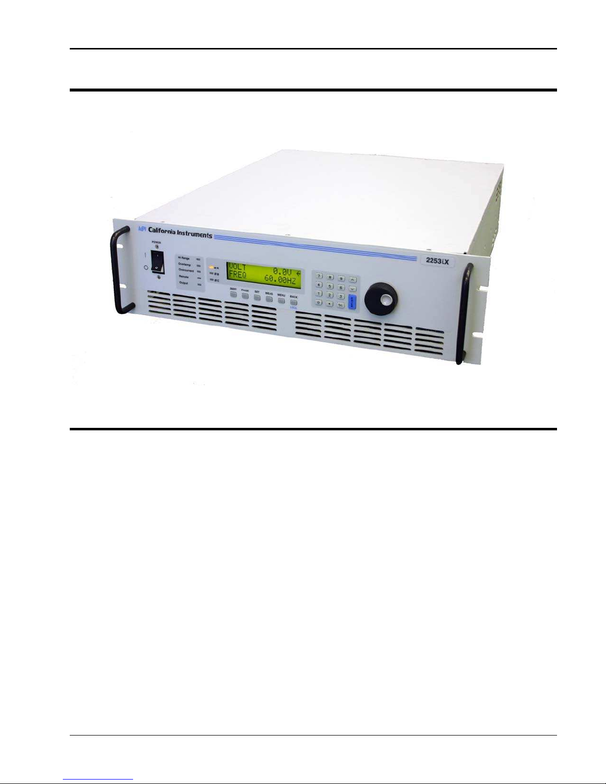
1.1 General Description
The Compact i/iX Series of AC Power Source is a family of high efficiency, rack mountable, AC Power
Sources that provide a precisely controlled output voltage with low distortion and measurements. In
addition, the unit provides measurements of voltage and current, and the iX models offer extensive
power analyzer capabilities with easy to use interface software. Standard output voltage ranges are
150 Vac and 300 Vac RMS. The 2253i/iX models operate in three-phase mode and provide a
maximum output power of 750VA per phase. A –MODE option is available which parallels all three
outputs in a single-phase mode of operation. A unique constant power mode allows for higher output
current at less than full-scale voltage effectively increasing the usability for many applications where
otherwise a higher power level AC source may be needed.
Read the installation instructions carefully before attempting to install and operate the Compact i/iX
Series power source.
Figure 1-1: Model 2253iX AC Source.
California Instruments 10

User Manual 2253i / 2253iX
1.2 iX and i Model Differences
The 2253iX offers additional features and functions over the 2253i model. Some of the features
available on the 2253iX such as the GPIB interface may be added as an option to the 2253i at the
time of order. Other features are exclusive to the 2253iX models.
Both models are based on the same AC power source hardware platform and share many common
components. The differences are primarily in configuration and options. This manual covers both
models. Some menus and screen shown in this manual may not apply to i model AC sources.
All 2253i/iX models are equipped with a USB and RS232 interface. The 2253iX also includes a GPIB
interface. The GPIB interface can be specified as an option on the 2253i models at the time of order.
An optional Ethernet interface (-LAN) is available on the 2253iX model only.
1.3 Manual organization and format
All user documentation for California Instruments power sources is provided on CDROM in electronic
format. (Adobe Portable Document Format) The required Adobe PDF viewer is supplied on the same
CDROM. This manual may be printed for personal use if a hardcopy is desired. To request a
hardcopy from California Instruments, contact customer service at
an additional charge for printed manuals.
support@calinst.com. There will be
This manual contains sections on installation, normal use, maintenance and calibration.
Refer to the iX Compact Series Programming manual for information on using the remote control
interface and command syntax. The programming manual (P/N 6005-961) is provided on the same
CDROM as this user manual.
California Instruments may make updated versions of this manual available from time to time in
electronic format through it’s website. To obtain an updated manual revision if available, check the
California Instruments Manual download page at www.calinst.com. You need to register as a
customer to obtain free access to manual and software downloads.
California Instruments 11
User Manual 2253i / 2253iX
2. Specifications
Specifications shown are valid over an ambient temperature range of 25 ± 5° C and apply after a 30
minute warm-up time. Unless otherwise noted, all specifications are per phase for sine wave output
into a resistive load. For three phase configurations or mode of operation, all specifications are for
Line to Neutral (L-N) and phase angle specifications are valid under balanced load conditions only.
Specifications for 2253i models are identical to those for the 2253iX except where noted.
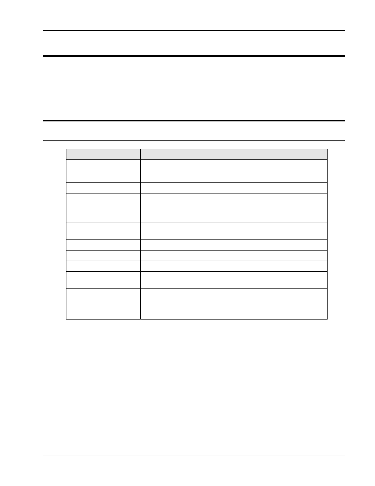
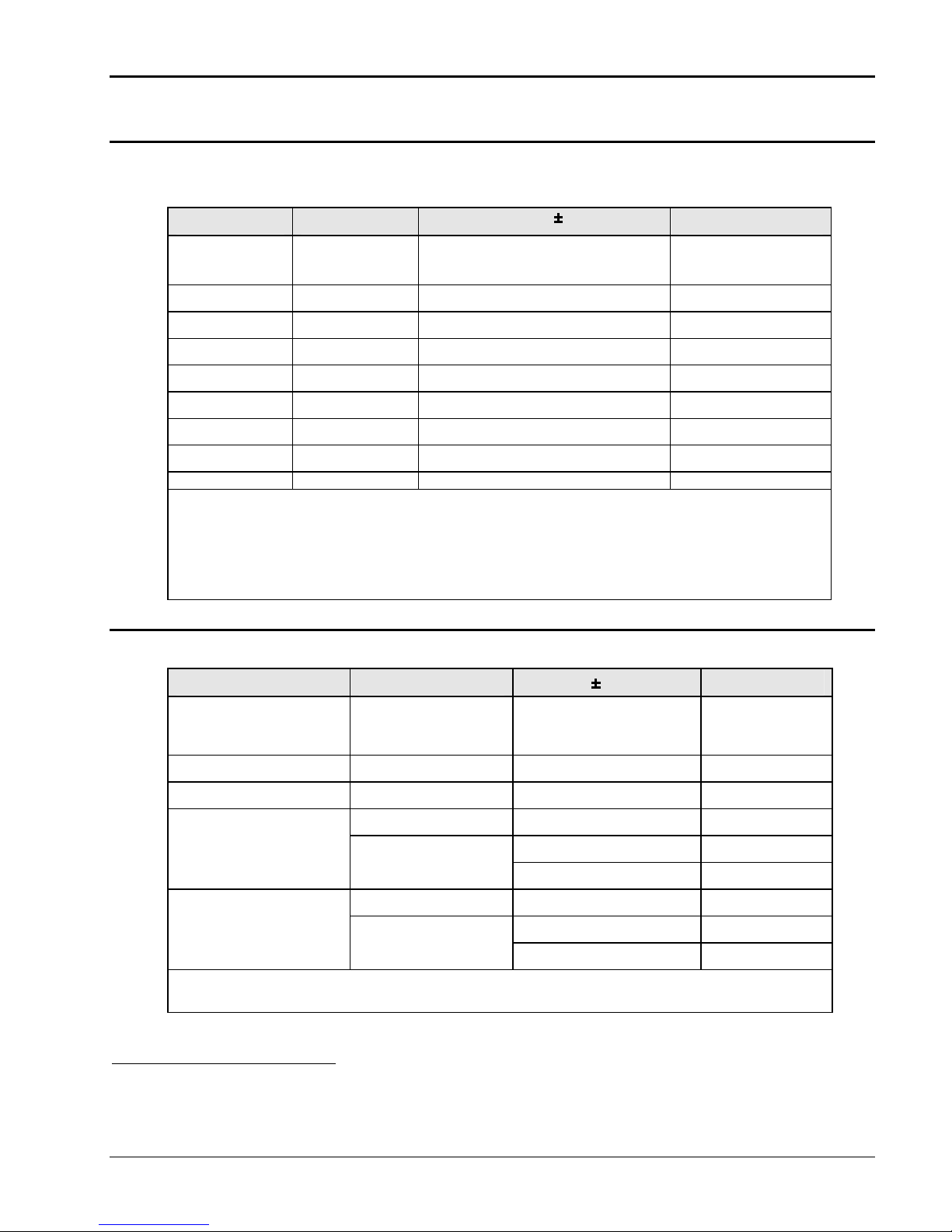
2.1 Electrical
2.1.1 Input
Parameter Specification
Line Voltage:
(single phase, 2 wire +
ground (PE))
Line VA: 2940 VA / 2850 W
Line Current at nominal
input voltage:
Line Current at low line
input voltage, full power:
Line Frequency: 47-63 Hz
Efficiency: 77 % (typical @ full load)
Power Factor: 0.98 (typical @ full load)
Inrush Current: < 160 Apk for less than 2 ms at 230V + 10% AC input
Hold-Up Time: > 10 ms
Isolation Voltage: 1350 VAC input to output
< 20 Arms @ 115V and 1500 VA output
(Note: Max. AC input current limited to 20 Arms.
Breaker may trip above 1500 VA output power)
< 15 Arms @ 230V and 2250 VA output
< 20 Arms @ 103.5V (Derated output power)
< 17 Arms @ 207V (Full output power)
< 80 Apk for less than 2 ms at 115V + 10% AC input
115 to 230 VAC ± 10 %
1350 VAC input to chassis
California Instruments 12
User Manual 2253i / 2253iX
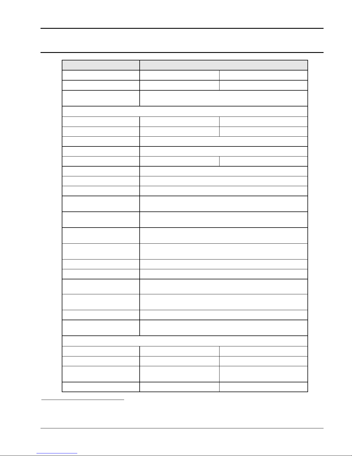
2.1.2 Output
Output Parameter Specification
Model 2253i 2253iX
Modes
No of Outputs
AC, DC AC, DC, AC+DC
3 standard
1 or 3 with –MODE option
Voltage
Ranges (L-N):
AC, AC+DC Mode
Low Vrange: 0 - 150 Vrms
High Vrange: 0 - 300 Vrms
DC Mode
Low Vrange: 0 - 200 Vdc
High Vrange: 0 - 400 Vdc
Programming Resolution: 0.1 V
Accuracy:
0.1% FS1 (from 5V to FS1)
(ALC mode ON)
Distortion THD2:
Load Regulation:
(ALC mode ON)
(At external sense connection with ext sense mode programmed.)
< 1 % 16 - 1000 Hz
(harmonics and noise to 300 kHz)
0.1 % FS
1
Voltage Sense modes: Internal
External
External Sense Up to 3 % of set voltage can be dropped across each load lead.
Line Regulation: 0.02% for 10% input line change
DC Offset Voltage:
(In AC mode)
Output Noise:
(20 kHz to 1 MHz, full R load)
< 100 mV
< 200 mV
< 20.0 mV
150V / 200V Range
RMS –
300V / 400V Range
RMS –
Output Coupling Direct coupled
Output Impedance (Z) (@
Z = Vrange * 0.001 / I_load
max current)
Current (with 200 – 230 VAC line input)
Output Mode 3 Phase 1 Phase (-Mode)
AC Mode
High Voltage range 2.5 Arms @ 300 V
3.25 Arms @ 230 V
Low Voltage range 5.0 Arms @ 150 V
1
FS (Full Scale) refers to highest available range, e.g. 300Vac in AC mode, 400Vdc in DC mode.
2
The distortion specification applies at 77% voltage range, max current and resistive load conditions.
7.5 Arms @ 300 V
9.74 Arms @ 230 V
15.0 Arms @ 150 V
California Instruments 13

User Manual 2253i / 2253iX
Output Parameter Specification
6.5 Arms @ 115 V 19.5 Arms @ 115 V
DC Mode
High Voltage range 1.25 Adc @ 400 V
1.63 Adc @ 300 V
Low Voltage range 2.5 Adc @ 200 V
3.25 Adc @ 150 V
3.75 Adc @ 400 V
4.88 Adc @ 300 V
7.5 Adc @ 200 V
9.74 Adc @ 150 V
AC+DC Mode
High Voltage range 1.25 Arms @ 300 V
1.63 Arms @ 230 V
Low Voltage range 2.5 Arms @ 150 V
3.25 Arms @ 115 V
3.75 Arms @ 300 V
4.88 Arms @ 230 V
7.5 Arms @ 150 V
9.74 Arms @ 115 V
Current Limit mode Programmable, CC or CV mode
Note: Constant power mode allows higher current at reduced voltage. Maximum current available at 77% of
voltage range. See Figure 2-1 through Figure 2-6 for voltage versus current profiles by model and
voltage range.
Note: Full power output available only when using 208-230 AC nominal input line. For 100-115V AC input
operation, maximum output power and current are limited by maximum input current of 20 A.
Maximum AC Peak Current
Model
AC mode, High Vrange
AC mode, Low Vrange
3 Phase 1 Phase (-Mode)
10 Apk
20 Apk
30 Apk
60 Apk
Crest Factor AC Current
Maximum CF at full scale
4:1
voltage rms current
Power
Model
AC Mode (208 – 230V
3 Phase 1 Phase (-Mode)
750 VA 2250 VA
nominal AC input)
AC Mode (100-115V nominal
500 VA 1500 VA
AC input)
DC Mode 500 W 1500 W
AC+DC Mode 375 VA 1125 VA
Frequency
Range: 16 Hz - 1000 Hz
Resolution1: 0.01 Hz [< 81.91 Hz]
0.1 Hz [> 82.0 to 819.1 Hz]
1 Hz [> 819 Hz]
Accuracy: ± 0.025 %
Temp. Coefficient ± 5 ppm of value / °C
Stability: ± 15 ppm of value
1
Programming resolution reduced if –LKM/-LKS option is installed. See paragraph 2.8.
California Instruments 14

User Manual 2253i / 2253iX
Note: All output specifications apply below the Current / Voltage rating line shown in the V/I
rating charts of section 2.1.2.1 through 2.1.2.3. Data is shown for three-phase mode.
For –MODE option, multiply current by 3.
California Instruments 15
User Manual 2253i / 2253iX
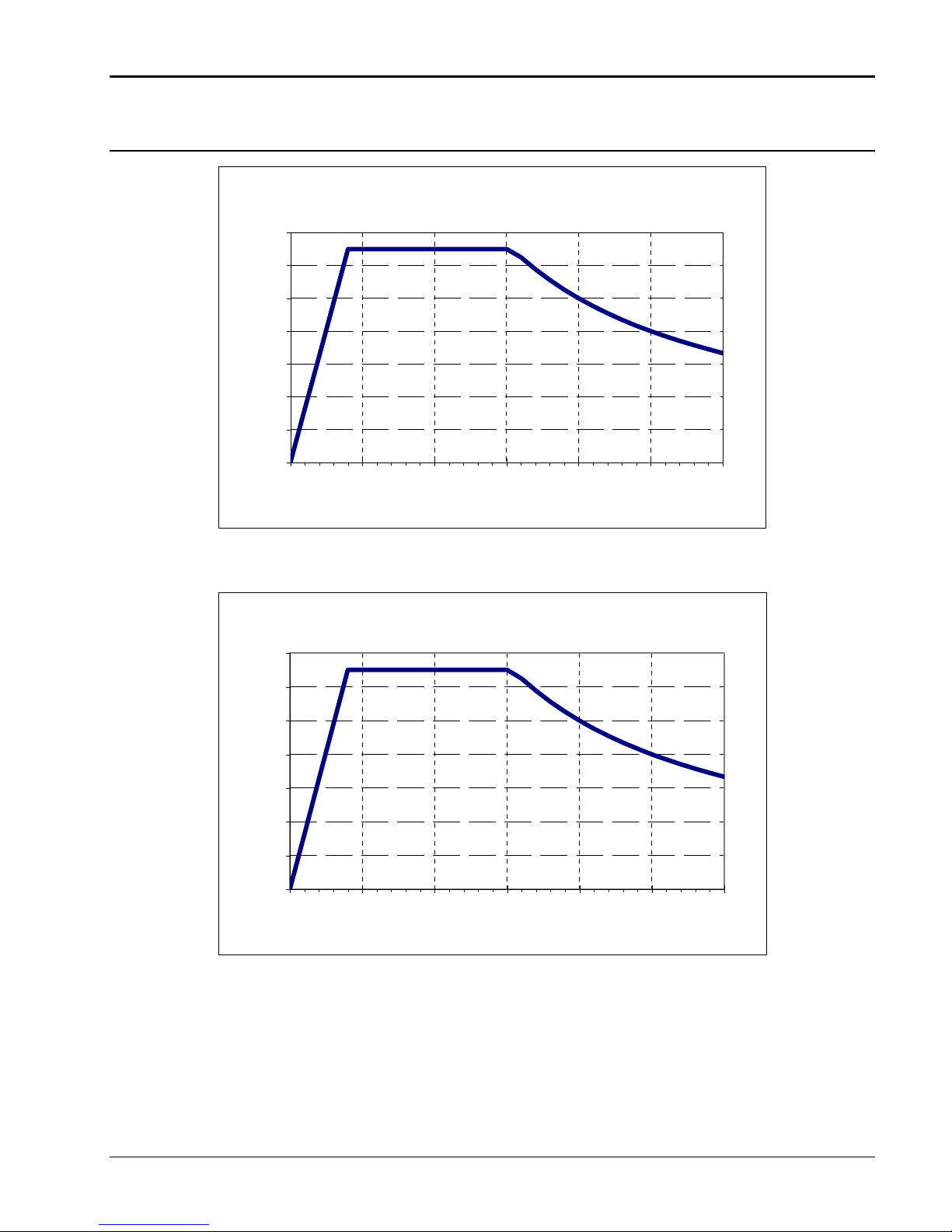
2.1.2.1 Voltage versus Current Rating Charts – AC Mode – 230V AC input
Figure 2-1: 2253i / iX Voltage / Current Rating Chart for 150V AC Range per phase – 230Vac in.
Figure 2-2: 2253i / iX Voltage / Current Rating Chart for 300V AC Range per phase – 230Vac in.
California Instruments 16
User Manual 2253i / 2253iX
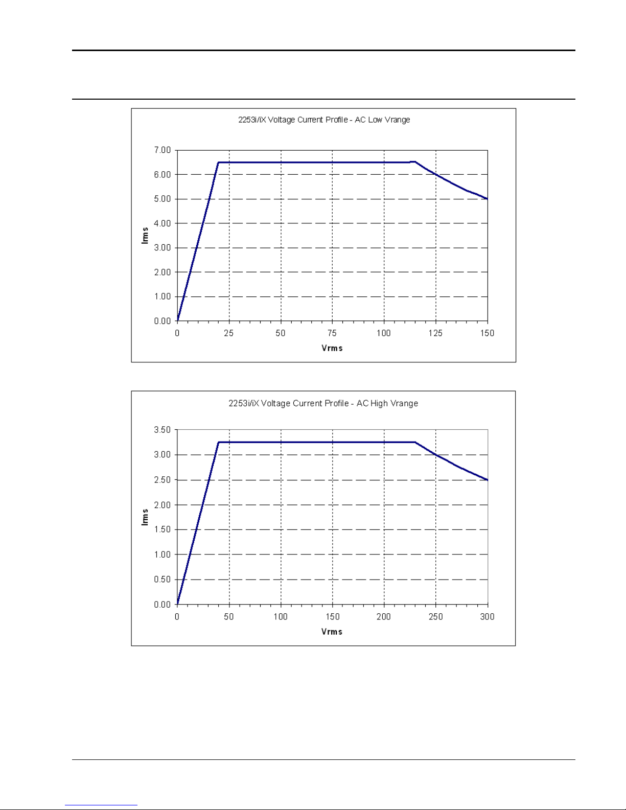
2.1.2.2 Voltage versus Current Rating Charts – AC Mode – 115V AC input
2253i/iX Voltage Current Profile - AC Low Vrange - 115V AC input
7.00
6.00
5.00
4.00
Irms
3.00
2.00
1.00
0.00
0 25 50 75 100 125 150
Vrms
Figure 2-3: 2253i / iX Voltage / Current Rating Chart for 150V AC Range per phase – 115Vac in
2253i/iX Voltage Current Profile - AC High Vrange - 115V AC input
3.50
3.00
2.50
2.00
Irms
1.50
1.00
0.50
0.00
0 50 100 150 200 250 300
Vrms
Figure 2-4: 2253i / iX Voltage / Current Rating Chart for 300V AC Range per phase – 115Vac in
California Instruments 17
User Manual 2253i / 2253iX
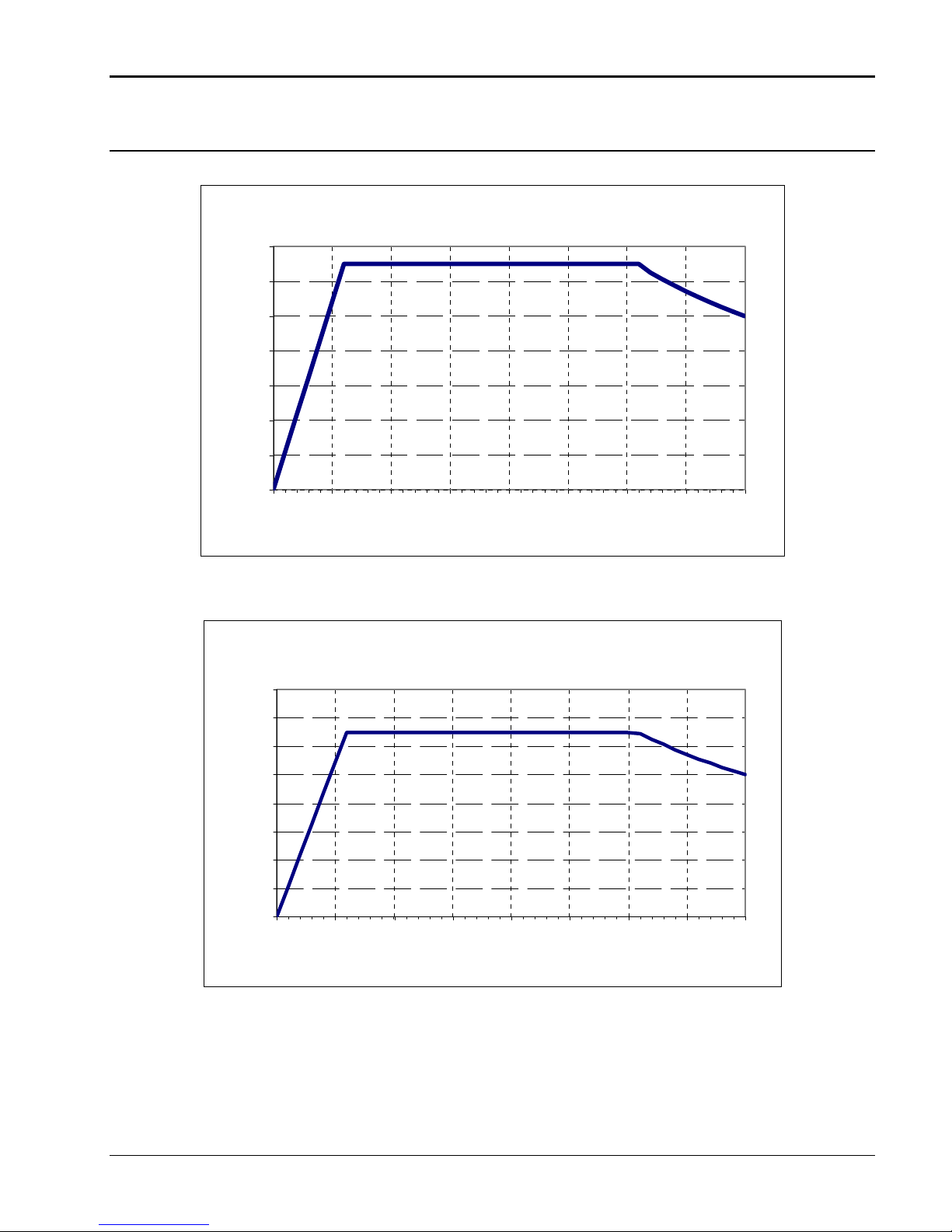
2.1.2.3 Voltage versus Current Rating Charts – DC Mode
2253i/iX Voltage Current Profile - DC Low Vrange
3.50
3.00
2.50
2.00
Idc
1.50
1.00
0.50
0.00
0 25 50 75 100 125 150 175 200
Vdc
Figure 2-5: 2253i / iX Voltage / Current Rating Chart for 200V DC Range per phase.
2253i/iX Voltage Current Profile - DC High Vrange
2.00
1.75
1.50
1.25
1.00
Idc
0.75
0.50
0.25
0.00
0 50 100 150 200 250 300 350 400
Vdc
Figure 2-6: 2253i / iX Voltage / Current Rating Chart for 400V DC Range per phase.
California Instruments 18
User Manual 2253i / 2253iX
2.1.3 Measurements
Measurement specifications apply to single chassis AC sources. See notes for other models and
configurations.
Parameter Range
Frequency1 16.00-1000.0 Hz 0.1 % 0.01 Hz to 81.91 Hz
Voltage 0 - 400 Volts 0.1 % 0.01 Volt
Phase angle 0 – 360° 0.5° 0.1°
Current 0 – 15 Amps 0.5 % 0.001 Amp
Peak Current 0 - 60 Amps 0.5 % 0.001 Amp
Crest Factor 1.00 –10.00 1.5 % 0.01
VA Power 0 - 4 KVA 0.5 % 1 VA
Real Power 0 - 4 KW 0.5 % 1 W
Power Factor 0.00 - 1.00 1 % 0.01
Note: Accuracy specifications are valid above 100 counts. For multi-chassis configurations, Current
and Power range and accuracy specifications are times the number of chassis.
Note: Frequency measurement specification valid for output > 20 Vrms.
Note: Crest Factor accuracy applies for Irms > 50% of max.
Note: Power Factor accuracy applies for PF > 0.5 and VA > 50% of max.
2.1.4 Harmonic Measurements
Harmonic measurement specifications apply to 2253iX model AC sources only.
Accuracy (± % FS)
Resolution
0.1 Hz to 819.1 Hz
1 Hz > 819.1 Hz
Parameter Range
Frequency fundamental 16.00 - 81.91 Hz
82.0 - 819.1 Hz
> 819.1 Hz
Frequency harmonics 16.00 Hz – 48 kHz 0.5% 0.1 Hz
Phase -180° – 180° 2° + 5°/kHz 0.1°
Voltage
Fundamental 0 - 400 Volts 0.5% 0.01V
Harmonic 2 - 50 0.5% + 0.5%/kHz 0.01V
Current2
Fundamental 0 - 15 Amps 0.5% 0.01A
Harmonic 3 - 50 0.5% + 0.5%/kHz 0.01A
Note: For multi-chassis configurations, current accuracy specifications are times the number of
chassis.
Accuracy (± % FS)
0.1% 0.01 Hz
Resolution
0.1 Hz
1 Hz
1
Frequency measurement specifications valid with output voltage of 20Vrms or higher. If output relay is open, frequency
measurement will return 0.0 Hz.
2
Second current harmonic measurement value not included.
California Instruments 19
User Manual 2253i / 2253iX
2.1.5 System Specification
Controller Features Specification
Trigger Input: External trigger source input. Requires TTL level input signal. Triggers
on negative edge. Response time 80 - 100 µs.
Function Strobe:
Trigger Out:
Non volatile memory
storage:
Waveforms i Series: Sine.
Transients Voltage: drop, step, sag, surge, sweep
Current Limit Modes: Two selectable modes of operation:
Control Interfaces
USB Standard USB 2.0 peripheral.
Logic output, active low. Pulse width > 400 µs. Function strobe is
generated on any voltage or frequency program change or output relay
open/close. (Mutually exclusive with Trigger Out.)
Logic output, active low. Pulse width > 400 µs. Trigger out is generated
based on user programmed transient trigger list. (Mutually exclusive with
Function Strobe.)
16 complete instrument setups and transient lists, 100 events per list.
50 User defined waveforms.
iX Series: Sine, square, clipped, user defined (50 waveforms)
Frequency: step, sag, surge, sweep
Voltage and Frequency: step, sweep
1. Constant current mode (voltage folds back with automatic recovery)
2. Constant voltage mode with output relay trip-off (Output relay
opens).
Note: Only one of the serial interfaces (USB, RS232 or LAN) can be
active at the same time. (Mutually exclusive).
Data transfer rate: 460,800 bps
Syntax: SCPI
Note: Use of the USB port to control more than one power
source from a single PC is not recommended, as communication
may not be reliable. Use GPIB interface for multiple power source
control.
RS232 Standard RS232 interface.
Data transfer rate: 9600 to 115,200 bps
Format: 8 data, 1 start, 1 stop, no parity.
Syntax: SCPI
IEEE-488 AH1, DC1, DT1, L3, RL2, SH1, SR1, T6
IEEE 488.2 and SCPI
Response time is 10 ms (typical)
(Requires –GPIB option on 2253i)
LAN / Ethernet RJ45 Connector, 10BaseT, 100BaseT or 1000BaseT,
Data transfer rate: 460,800 bps
Protocol: TCP/IP.
(-LAN Option on 2253iX only. RS232 interface is disabled with –LAN
option)
California Instruments 20
User Manual 2253i / 2253iX
2.1.6 Unit Protection
Parameter Specification
Input Over current: Input Circuit Breaker. This breaker protects the equipment and is also
used to turn the unit on or off.. AC input connection should be made per
local electrical code.
Input Over voltage
Transients:
Output Over current: Adjustable level constant current mode with programmable set point.
Output Short Circuit: Peak and RMS current limit.
Over temperature: Automatic shutdown.
Surge protection to withstand EN50082-1 (IEC 801-4, 5) levels.
California Instruments 21
User Manual 2253i / 2253iX
2.2 Mechanical
Parameter Specification
Dimensions: Height: 5.25 inches (13.3 cm)
Depth: 23 inches (58.4 cm)
Width: 19 inches (48.3 cm)
All dimensions are per chassis. For /2 model configurations, multiply
height by 2 for total height. Width includes integrated front panel rack
mount ears.
Equipment Rack depth
requirement
Rack slide mount The rack mount slide (-RMS option) mounting holes centerlines on the
Unit Weight:
Material: Steel chassis with aluminum top cover
Finish: Powder coated external surfaces, color medium gray.
Cooling: Fan cooled with air intake on the sides and front, and exhaust to the rear.
Acoustic Noise
(Supplemental
specification)
Internal Construction: Modular sub assemblies.
Rear Panel
Connections:
25 inches (63.5 cm)
side of the power source are 2.30 inches / 58.4 mm above the bottom
edge of the front panel.
Net: 58 lbs / 26 Kg approximately
Shipping: 76 lbs / 35 Kg approximately
Variable speed fan control.
Measured at 1 m distance:
Fan speed: Low power mode Full power mode
Front of unit: 41 dBA 51 dBA
Rear of unit: 43 dBA 56 dBA
(See section 3 for description of connections)
• AC input screw terminal block.
• AC output screw terminal strip.
• External sense connector.
California Instruments 22
• USB, RS232, GPIB (option on i), LAN (option on iX)
• Auxiliary I/O
User Manual 2253i / 2253iX
2.3 Environmental
Parameter Specification
Operating Temp:
Storage Temp:
Altitude: < 2000 meters
Relative Humidity:
Operating Environment Indoors Use Only. Ground benign.
Vibration: Designed to meet NSTA project 1A transportation levels.
Shock: Designed to meet NSTA project 1A transportation levels.
0° to +40° C, full power.
+32° to +104° F, full power.
-40° to +85 °C.
-40° to +185° F.
< 6000 feet
0-80 % RAH, non-condensing maximum for temperatures up to 31°C
decreasing linearly to 50% at 40°C.
California Instruments 23
User Manual 2253i / 2253iX
2.4 Front Panel Controls, Indicators and Display
Controls:
Shuttle knob: The rotating knob may be used to adjust settings while in the SET menu.
Up/down arrow keys: A set of up and down arrow keys is used to move the cursor position in
Function keys:
Keypad: A numeric keypad contains numbers 0 through 9 as well as up and down
Indicators and Display:
Status indicators: Status indicators inform the user of important power source conditions:
LCD character display: High contrast backlit LCD display. An adjustable viewing angle makes it
In all other menus, the shuttle may be used to change parameter values
and settings.
all menus. This allows quick selection of the desired function or
parameter.
ON/OFF key for output relay control.
PHASE This key allows selection of an individual phase or all three
phases.
SET key will show output voltage and frequency setting.
MEAS key displays the measurement screens. Measure key will display
measurement values for selected phase or phase A if all three phases
are selected.
MENU key selects main menu.
BACK key is used to back up to previous screen or erase the last digit
entered. This key also serves as a “GOTO LOCAL” key when the unit is
in remote.
arrow keys, an Enter key, decimal point and polarity change (+/-) key.
The up and down arrow keys are used to move the cursor position in all
menus. This allows quick selection of the desired function or parameter.
The Hi Range indicator is lit any time the unit is switched to the high
voltage range.
The Overtemp LED illuminates when internal heat sink temperatures are
too high.
The Overcurrent LED indicates that maximum programmed current limit
is being drawn at the output.
The Remote LED informs the user that the unit is under remote control.
The Output indicator is on when the power source output relays are
closed.
The Phase A, B, C indicators illuminate when either phase A, B, C or all
3 phases are selected using the PHASE button.
easy to read from all practical locations.
California Instruments 24
User Manual 2253i / 2253iX
2.5 Special Features
Controller Features
Controller: Programmable controller front panel assembly.
Mode Available single-phase mode option (-MODE) allows the output of all
three amplifiers to be combined on phase A output terminal. No external
switching or reconnection to the load is required.
Output Relay: Standard output relay feature to isolate power source from the load. Each
phase and the neutral (common) output is disconnected when the output
relay opens.
Output On/Off: The output relay can be used to quickly disconnect the load. A yellow
status indicator displays the status of the output relay.
External Trigger Output
or Function Strobe
Clock and Lock Mode Enables two or more independent iX power systems to be phase
Trigger Input A TTL input signal may be used as a trigger source for output changes
An external TTL output is available which may be used to trigger other
equipment. The TTL output can be controlled by the transient
programming system. This requires the trigger mode to be set to EXT
(factory default). This can only be done over the computer interface using
the OUTP:TTLT:MODE TRIG command.
It can also be configured to generate an output pulse any time the
voltage, frequency, current limit or phase programming is updated. This
requires the trigger mode to be set to FSTR. This can only be done over
the computer interface using the OUTP:TTLT:MODE FSTR command.
This mode is compatible with the CI Lx/Ls Series.
The Trigger Output (Trig Out) / Function Strobe is an active low TTL
signal with a duration of no less than 400 us.
synchronized to each other. One system (-LKM) acts as the master, the
other(s) (-LKS) as auxiliaries. The –LKS units are synced to the –LKM
unit. Refer to section 3.9 for details on Clock and Lock mode.
programmed on the AC power source transient system. This requires the
trigger source to be set to EXT. This can only be done via one of the
computer interfaces. An external trigger source may be used to control
the execution of output sequences that have been pre-programmed into
the power source transient system. Refer to i/iX Series Programming
Manual (6005-961) for details.
California Instruments 25
User Manual 2253i / 2253iX
2.6 Available Options – i Series
Interface Options
-GPIB GPIB Remote control interface. This option is not field installable and
must be specified at the time of original unit order.
Misc. Options
-ABL Atlas Based Language Extension. The ABLE command language
provides bus compatibility with 9012 PIP controllers.
-EXT External Signal Input. This option allows a 0-5Vrms AC signal to be used
as the oscillator signal. In this mode, the AC power source acts as an AC
amplifier. No programmable current limit is available and the output
frequency of 1000 Hz should not be exceeded. Mutually exclusive with –
RPF and –RPV options.
-MODE Mode option allows all three amplifier outputs to be combined on phase A
output terminal. No external switching or reconnection to the load is
required.
-RMS Set of 2 Rack mount slides. (Left and Right) Recommended to mount
chassis in 19-inch instrument cabinet.
-RPV Remote programming voltage. DC voltage input 0 to 10 VDC for 0 to fullscale output voltage programming.
-RPF Remote programming frequency. DC voltage input 0 to 10 VDC or 0 to 5
VDC for 0 to 800 Hz output frequency programming. Input impedance is
20 Kohm (RPF10) or 10 Kohm (RPF5).
This option is mutually exclusive with the –LKS option.
-WHM Watt-hour measurement option.
California Instruments 26
User Manual 2253i / 2253iX
p
2.7 Available Options – iX Series
Interface Options
-LAN Ethernet LAN interface connection. RJ45 connector. This option is not
field installable and must be specified at the time of original unit order.
Note: The RS232 interface is disabled if –LAN option is specified.
Test Options
-160 RTCA/DO-160 Revision D and E, EuroCAE test firmware. Revision E
requires use of iXCGui software (included).
-704 Mil-Std 704 Revision D and E test firmware. Revision A, B, C and F
requires use of iXCGui software (included).
-704F Mil-Std 704 Revisions A through F test firmware.
-A350 Airbus A350 / ABD0100.1.8.1 test software. Requires use of iXCGui
software (included).
-ABD Airbus ABD0100.1.8 test software. Requires use of iXCGui software
(included).
-AMD Airbus A400M Directive AMD24 test software. Requires use of iXCGui
software (included).
Misc. Options
-B787 Boeing B787-0147 test software. Requires use of iXCGui software
(included).
-ABL Atlas Based Language Extension. The ABLE command language
provides bus compatibility with 9012 PIP controllers.
-EXS External Sync Input. This option changes the external trigger input to an
external sync input. The output frequency will be synced to the square
wave TTL level sync signal provided.
-EXT External Signal Input. This option allows a 0-5Vrms AC signal to be used
as the oscillator signal. In this mode, the AC power source acts as an AC
amplifier. No programmable current limit is available and the output
frequency of 1000 Hz should not be exceeded. Mutually exclusive with –
RPF and –RPV options.
-LKM Clock and Lock Master. Enables synchronizing outputs of two iX AC
sources. This mode supports a frequency range of 16 to 819 Hz.
The –LKM applies to the master unit. This option is not field installable
and must be specified at the time of original unit order.
-LKS Clock and Lock Auxiliary. See -LKM for details. The –LKS applies to the
auxiliary unit. (See Notes, see section 3.9.) This option is not field
installable and must be specified at the time of original unit order.
This option is mutually exclusive with the –RPF option.
-MODE Mode option allows all three amplifier phase outputs to be combined on
phase A output terminal. No external switching or reconnection to the
load is required.
-RMS Set of 2 Rack mount slides. (Left and Right) Recommended to mount
-RPV Remote programming voltage. DC voltage input 0 to 10 VDC for 0 to full-
-RPF Remote programming frequency. DC voltage input 0 to 10 VDC or 0 to 5
California Instruments 27
chassis in 19-inch instrument cabinet.
scale output voltage programming. Mutually exclusive with –EXT option.
VDC for 0 to 800 Hz out
ut frequency programming. Input impedance is
User Manual 2253i / 2253iX
20 KOhm.
This option is mutually exclusive with the –LKS and –EXT option.
-WHM Watt-hour measurement option.
2.8 EXT Option - Supplemental Specifications
When the EXT option is installed, the amplifier is used in an open loop mode and none of the regular compact iX
Series output specifications apply. This option also precludes the presence of the –RPV and –RPF option.
An external signal input is provided for each phase. The phase A EXT input pins is also used on the Auxiliary I/O
connector for the RPVA option so the RPV and EXT options are mutually exclusive. The voltage reference (VOLT
REF) on the CONTROL screen of the power source controller must be set to EXT to use this feature. See section
8.4 for EXT option operating instructions.
Parameter Supplemental Specification
Input:
Level 0 – 5 Vrms / -7.5 Vpk to +7.5 Vpk max. for 0 to 300Vrms. (Gain = 35.6 dB)
Impedance < 4 KOhm
Output:
Allowable Frequency:
Range 16 – 1000 Hz
Freqeuncy Response
Phase Phase offsets determined by provided external signal inputs A, B, C.
Isolated inputs, RPVA, EXTB, EXTC to analog common inputs on DB15
Auxiliary I/O (J18)
Voltage range is fixed to 300V AC range.
0 – 300 Vac RMS
See Figure 2-7.
California Instruments 28

User Manual 2253i / 2253iX
2.8.1 Typical Frequency Response – EXT Option
Typical performance for EXT option models in the 300VAC range operating at 230Vrms. EXT is
calibrated at 60 Hz.
230V Frequency Response
240.00
235.00
230.00
225.00
220.00
Voltage (V)
215.00
210.00
205.00
200.00
No Load
Full Load
0 200 400 600 800 1000 1200
Frequency (Hz)
Figure 2-7: EXT Option Frequency response 300VAC Range.
California Instruments 29
User Manual 2253i / 2253iX
2.9 LKM / LKS Options - Supplemental Specifications
The Clock and Lock option enables two or more independent 22531iX power systems to be phase synchronized
to each other. One system (-LKM) acts as the master, the other(s) (-LKS) as auxiliaries. The –LKS units are
synced to the –LKM unit. Refer to section 3.9 for details on Clock and Lock mode.
The following supplemental specifications apply when the 2253iX is configured with the Clock and Lock option. (LKM or –LKS).
Parameter Supplemental Specification
Voltage:
Voltage Distortion Standard specifications apply.
Frequency:
Range 16 – 819 Hz
Resolution 0.1 Hz
Accuracy ± 0.025%
2.10 RPF Option - Supplemental Specifications
The –RPF option allows an external DC reference to be used to program the output frequency. The following
supplemental specifications apply when the 2253i/iX is configured with the remote programming frequency option.
(-RPF).
Note that loss of input signal while in RPF mode could result in a DC output from the AC source even though it is
in AC mode. If this is potentially damaging to the EUT, care should be taken to always have a minimum input
signal level. See section 3.7.4 for RPF input connection.
Parameter Supplemental Specification
Voltage: Input
Voltage Distortion Standard specifications apply.
Frequency: -RPF Range
Resolution 0.1 Hz
Accuracy ± 1 %
0 to 5 Vdc or 0 to 10 Vdc for 0 – 800 Hz output.
0 – 819 Hz for 0 to 10 Vdc input.
2.11 WHM Option - Supplemental Specification
The following measurement accuracy specifications apply to the Watt Hour meter mode of operation:
Parameter Specification
Watt-Hour
Range: 0 – 999,999.9 WH
Resolution: 0.1 WH
Accuracy:
Etime
Range:
Resolution:
0.5% R +10 WH
0:00:00 to 9999:59:59
1 sec
Accuracy:
California Instruments 30
0.025 %
 Loading...