

California Faucets Widespread Lavatory Faucet User Manual
WIDESPREAD FAUCETS
(71, 72, & 73 Series)
800-822-8855
www.calfaucets.com
R
IMPORTANT
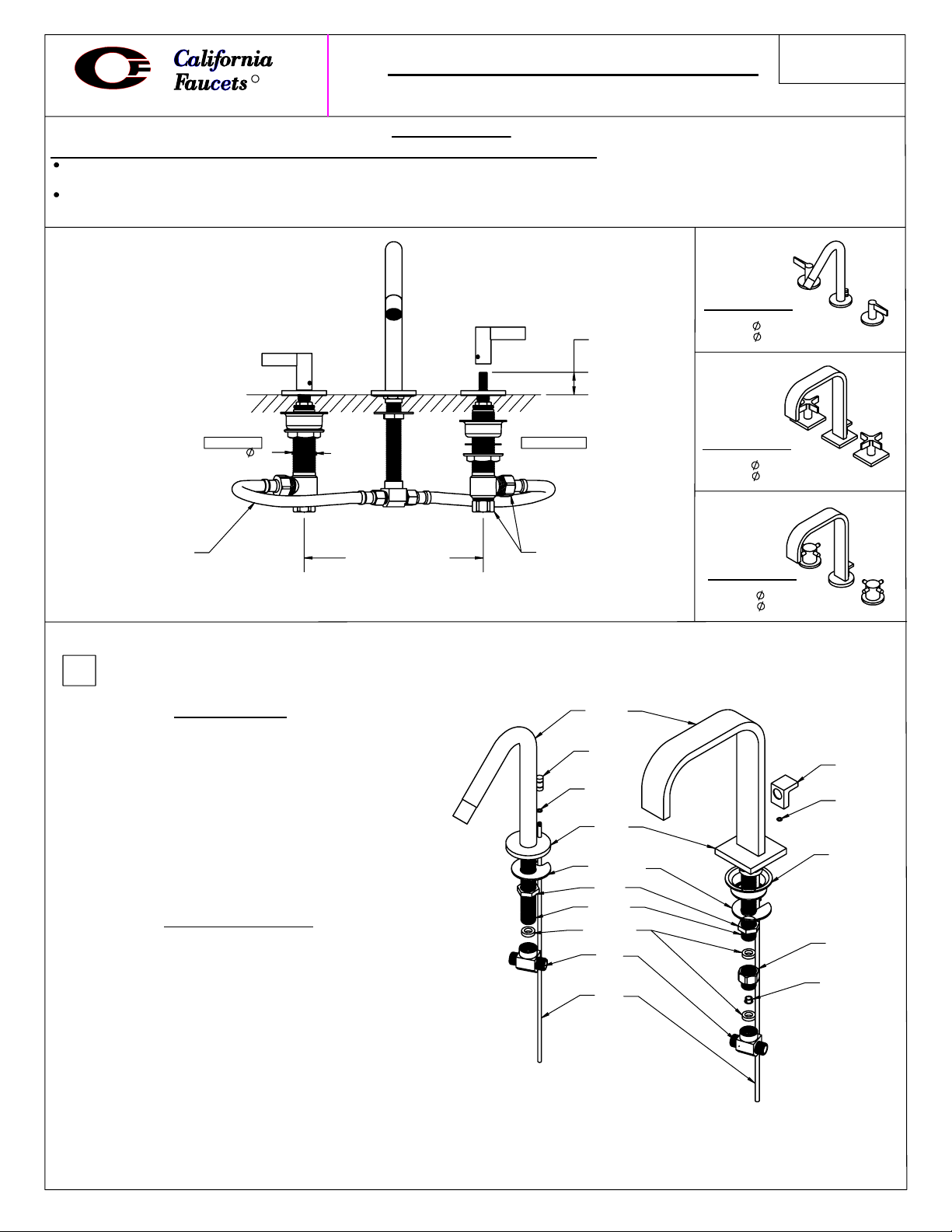
Due to the thin wall tubular design of this spout, please note the following
:
INSTALLATION
INSTRUCTIONS
Spout is not meant to be used as a support or grab device. Any excessive weight, pulling or grabbing of spout may
cause damage or injury and will void the warranty.
It may be necessary to initially operate at full flow, then reduce the flow to retain the desired “sheet” flow effect at
lower operating water volume (72/73 /series only).
#7102
"A" = 1"
THROUGH-HOLE
"A" MIN
SPOUT:
VAVLE:
#7202
"A" = 3/4"
1-1/8"
1"
Fig. 1
1/2"X3/8"X12"
FLEX LINE
HOT SIDE
All Widespread faucets meet A112.18.1 - 2.2gpm/8.3 L/min.
1
"
8" - 16" CENTERS
***NOTE: SHUT OFF WATER SUPPLY BEFORE BEGINNING INSTALLATION***
1
Install spout and lift rod with lift knob:
FOR 71 SERIES
-Remove TEE, NUT, and notched WASHER.
-Insert SPOUT thru center hole of sink/countertop.
-Slip notched WASHER over spout SHANK.
-Align notch for lift ROD to pass thru then thread
NUT onto the spout SHANK.
-Align SPOUT and tighten NUT firmly.
-Place rubber WASHER into top of TEE and tighten
assembly onto spout SHANK.
-Attach lift KNOB onto lift ROD and slide O-RING up.
-Insert lift ROD down through spout BASE.
FOR 72 & 73 SERIES
-Remove TEE, HOUSING, NUT, WASHER and SPACER.
-Insert SPOUT thru center hole of sink/countertop.
-Slip SPACER and notched WASHER onto spout
SHANK. Align notch for lift ROD to pass through then
thread NUT onto the spout SHANK.
-Align SPOUT and tighten NUT firmly.
-Place rubber WASHER into top of restrictor HOUSING
and tighten assembly onto spout SHANK.
-Place rubber WASHER into top of TEE and tighten
assembly onto restrictor HOUSING.
-Attach lift KNOB onto lift ROD and slide O-RING up.
-Insert lift ROD down through spout BASE.
(See Fig. 2A)
(See Fig. 2B)
COLD SIDE
1/2" NPSM
71 Series
Fig. 2A
SPOUT
KNOB
O-RING
BASE
NOTCHED
WASHER
NUT
SHANK
RUBBER
WASHER
TEE
ROD
THROUGH-HOLE
SPOUT:
VAVLE:
1-1/4"
1"
#7302
"A" = 1"
THROUGH-HOLE
SPOUT:
VAVLE:
1-1/4"
1"
KNOB
O-RING
SPACER
HOUSING
FLOW
RESTRICTOR
72 & 73 Series
Fig. 2B
7102-INSTL_081120
P1
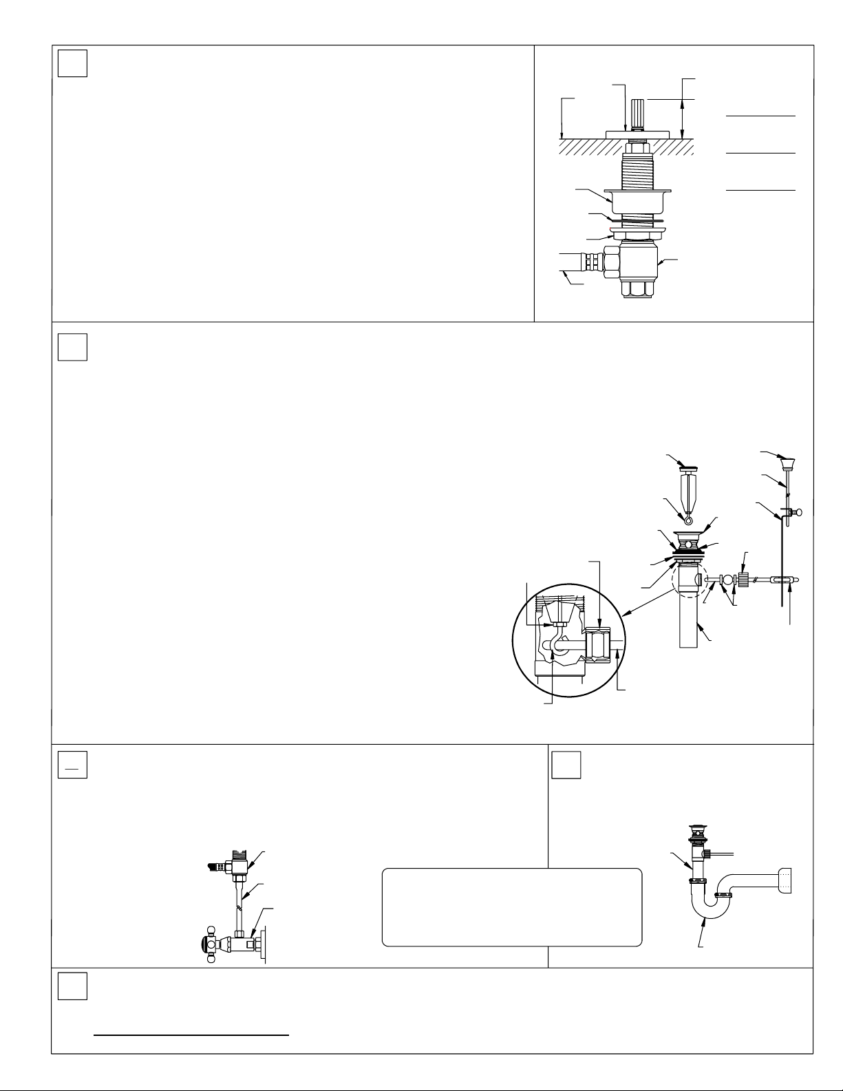
Install valve bodies
2
NOTE:
Hot & cold valves are labeled:
(See Fig. 1 & 3)
RED
= hot &
:
BLUE
= cold.
-Remove top nut and discard.
-Turn bottom nut with fiber washer down the valve until it stops.
-Place spacer cup onto valve oriented correctly as shown.
-Insert valve through hole from below.
-Attach and thread escutcheon onto threads below stem and
adjust valve to scheduled height "A".
-Place handle onto stem allowing minimal gap between escutcheon and
handle. Tighten setscrews with Allen key provided.
-Align handle in desired position and tighten the bottom nut to secure valve.
NOTE: Align square escutcheon on 7202 Series prior to securing valve.
-Attach flex lines between valves and spout tee.
-Flex lines shall be handtightened, then tighten 1/4 to 1/2 turn with wrench.
(wrench not supplied).
Escutcheon
Sink/
Countertop
Spacer
Cup
Fiber
Washer
Bottom
Nut
Flex
Line
"A"
7102 Series
"A" = 1"
7202 Series
"A" = 3/4"
7302 Series
"A" = 1"
Valve
Fig. 3
Install pop-up assembly
3
(See Fig 4 & 5)
:
-Separate drain collar from pop-up assembly.
-Apply silicon caulking to underside of drain collar.
"Plumbers Putty" or any oil based sealants!
NOTE:
Use of anything other than
Do not use
silicon caulking will VOID the finish warranty.
-Insert drain body from underside through sink. Slowly screw on drain
collar, align with ball rod hole facing back wall, then gently pull down into
sink and firmly tighten brass nut from below.
-Remove tailpiece from drain body and apply teflon tape, approx. 3 to
5 wraps around threads and reinstall into bottom of drain body.
-Insert stopper in collar and hold with eye-screw hole facing back.
If necessary, adjust stopper eye-screw height by loosening lock nut and
rotating counter-clockwise. Tighten lock nut
(See Fig. 4)
.
-Remove spring clip from ball rod.
-Remove nut and cone washers and slide onto end of ball rod.
-Insert ball rod into drain body below so short end of ball rod end fits
in stopper eye-screw hole. Snug ball rod nut (do not over tighten).
Ball rod must move up & down freely
(See Fig. 4)
.
-Insert lift rod through top of spout and then through hole rod strap
underneath sink. Tighten thumb-screw of hole rod strap
against lift rod and connect to ball rod by gently pinching locking
spring clip and sliding one side of spring clip onto ball rod.
-Insert hole strap onto ball rod, then pinch spring clip together to fit
on ball rod.
Lock
Nut
Adjustable
Eye-Screw
Nut
Fig. 4
Stopper
Adjustable
Eye-Screw
Rubber
Washer
Fiber
Washers
Brass
Nut
Ball
Rod
Drain
Collar
Drain
Rim
Ball
Rod
Drain
Tailpiece
Fig. 5
Lift Knob
Lift
Rod
Hole Rod
Strap
Nut
Cone
Washers
Spring
Clip
Connect faucet to water supply
4
IMPORTANT:
valve bodies. Debris remaining in the line will damage valve bodies and
cause leaking. Failure to flush the lines could result in voiding the warranty.
-Connect supply risers from the angle stops.
Turn on Water Supply:
6
Operate hot and cold valves: Inspect all joints and fittings for leaks.
NOTE: Due to sediment in the water it may be necessary on occasion to remove the aerator/flow restrictor and clean the
screen with a soft bristle toothbrush.
IMPORTANT CLEANING NOTICE: Please refer to
with a soft, damp cloth.
7102-INSTL_081120
(See Fig. 6)
:
Flush supply lines of all debris prior to connecting to lavatory
Valve
Body
Fig. 6
Supply Riser
(not supplied)
Angle Stop
(not supplied)
P-trap, angle stops, and supply risers
are not supplied. We recommend genuine
Cal-Trim parts available at your authorized
California Faucets dealer.
Finish Care Instructions
Never use acids, harsh abrasives or detergents.
5
Install "P" trap
-Connect your waste "P" trap
(See Fig. 7)
to the drain tailpiece.
Drain
Tailpiece
NOTE:
"P" Trap
(not supplied)
for complete cleaning information. Wipe frequently
:
Fig. 7
P2
 Loading...