

California Faucets Vessel Deck Faucets User Manual
Single Hole Lavatory Faucet with Pop-Up Drain
CF-3301-1 CF-3501-1
CF-4201-1 CF-6201-1
Installation Instructions
CALIFORNIA FAUCETS RECOMMENDS THAT ALL PLUMBING PRODUCTS BE INSTALLED
BY A LICENSED PROFESSIONAL
IMPORTANT: Read all instructions prior to installation and provide copy of instructions to consumer.
Operating Specifications:
Recommended Supply Pressure: 20 to 70 psi
* If water pressure exceeds 70 psi, install a Pressure-Reducing Valve (RPV).
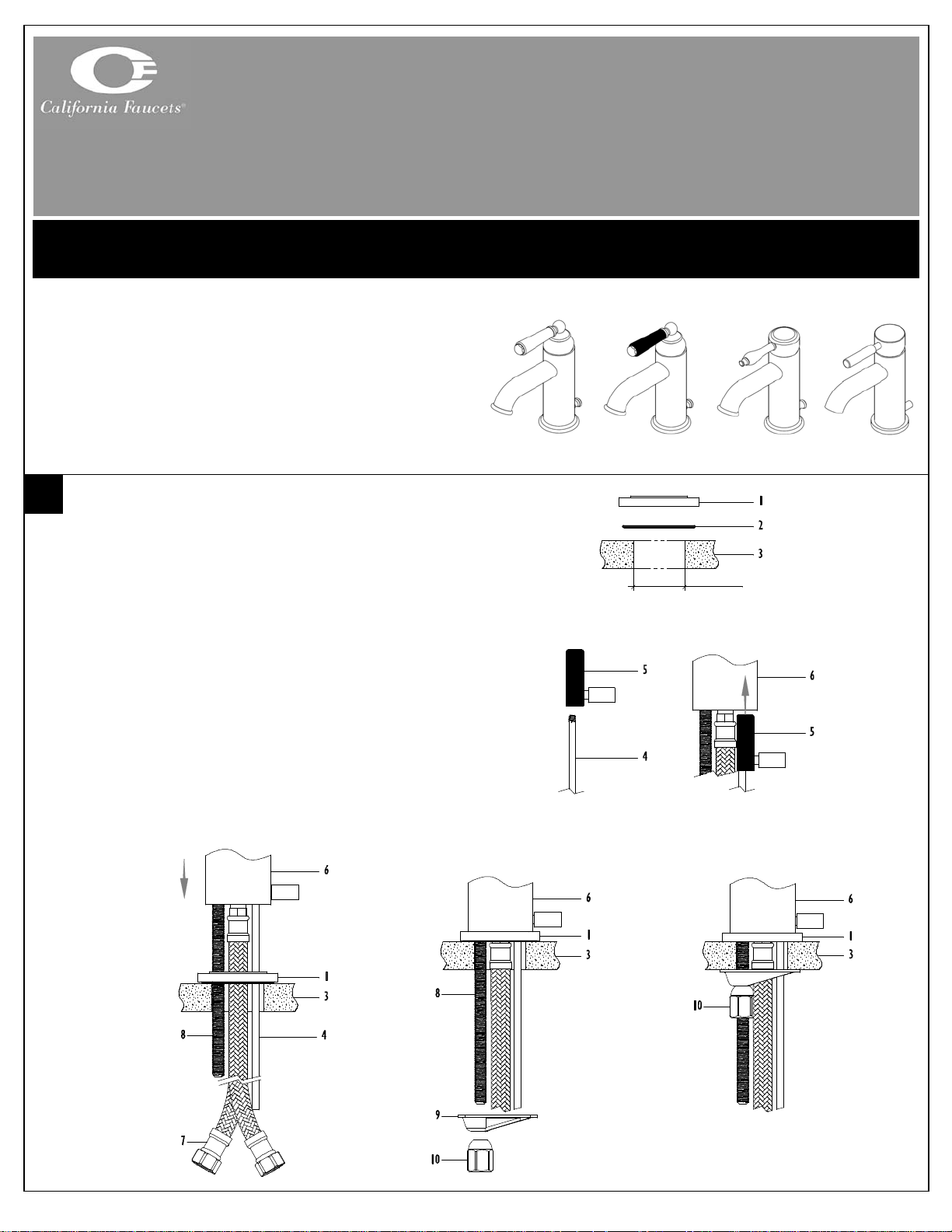
INSTALLING FAUCET TO SINK/DECK
*
CF-3301-1 CF-3501-1 CF-4201-1 CF-6201-1
• Insert O-RING (2) into bottom of BASE RING (1) and
center over sink/deck THROUGH-HOLE (3)
NOTE: Recommended sink/deck THROUGH-HOLE is Ø1-d”
• Attach LIFT ROD (4) to LIFT ROD GUIDE (5) and
insert into bottom of BODY (6)
• Insert FLEX HOSE (7) (one at a time), LIFT ROD (4) and
THREADED ROD (8) though BASE RING (1) and
sink/deck THROUGH-HOLE (3)
• Place BODY (6) on top of BASE RING (1)
• From underside of sink/deck THROUGH-HOLE (3),
place MOUNTING BRACKET (9) and NUT (10) onto
THREADED ROD (8)
• Tighten NUT (10) until BODY (6) and BASE RING (1) is
secure to sink/deck
Ø1-d”
CF-XX01-1_ii_100601.doc Pg 1
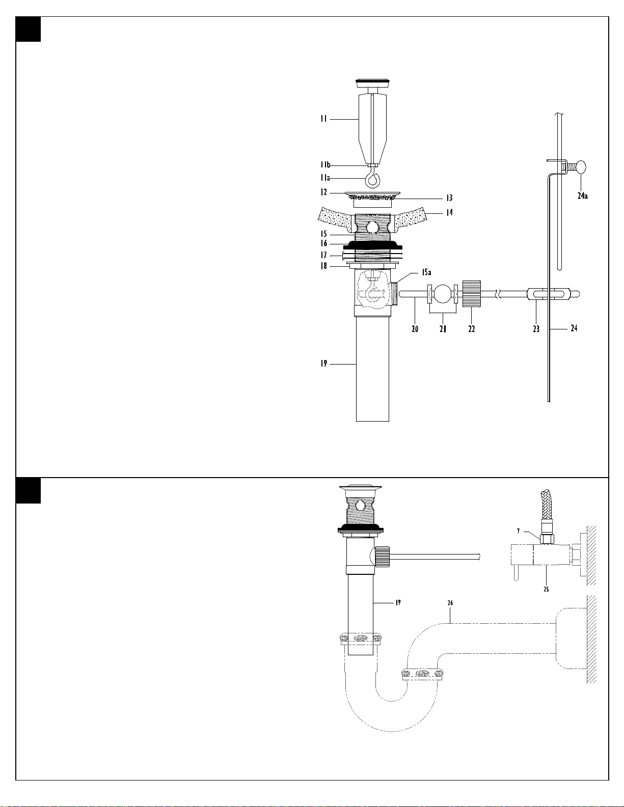
INSTALLING POP-UP DRAIN
• Remove COLLAR (12) from pop-up assembly and apply
SILICONE CAULK (13) (or equivalent) to underside of
COLLAR (12)
CAUTION: Do not use or any oil base sealant that may damage finish
• Insert DRAIN BODY (15) from underside through sink
DRAIN HOLE (14) & attach to COLLAR (12)
• Align BALL ROD HOLE (15a) toward LIFT ROD (4) and
firmly tighten FLANGE NUT (18) against FRICTION
WASHER (17), MACK WASHER (16) and sink DRAIN
HOLE (14)
• Remove TAILPIECE (19) from DRAIN BODY (15), apply
thread sealant to TAILPIECE (19) threads and tighten
into DRAIN BODY (15)
• Insert STOPPER (11) into COLLAR (12) & rotate EYE-
SCREW (11a) to accept BALL ROD (20)
NOTE: If necessary, adjust stopper eye-screw height by loosening LOCK
NUT (11b) and rotating EYE-SCREW (11a), retighten LOCK NUT (11b)
• Remove spring CLIP (23) from BALL ROD (20)
• Remove NUT (22) and both CONE WASHERS (21)
from DRAIN BODY (15) and place on BALL ROD (20)
as shown
• Insert BALL ROD (20) with CONE WASHERS (21) into
BALL ROD HOLE (15a) and through EYE-SCREW (11a)
• Tighten NUT (22), but allow BALL ROD (20) to freely
move up and down
• Place STRAP (24) onto LIFT ROD (4) and tighten
THUMB-SCREW (24a)
• Place one end of CLIP (23) onto BALL ROD (20), then
STRAP (23), gently squeeze CLIP (23) and slide other
end of CLIP (23) onto BALL ROD (20)
• Check proper operation of STOPPER (11) and adjust by
sliding STRAP (24) on LIFT ROD (4)
SUPPLY & WASTE CONNECTIONS
• Connect blue colored FLEX HOSE (7) to cold SUPPLY
VALVE (25) and red colored FLEX HOSE (7) to hot
SUPPLY VALVE (25)
IMPORTANT: Flush supply lines and valves prior to installation to prevent
damage and malfunction of cartridge
• Connect waste P-TRAP (26) to drain TAILPIECE (19)
NOTE: Supply valves and P-Trap are not supplied with faucet. See CAL
TRIM for complete selection of matching products in desired finish
• Turn on cold and hot SUPPLY VALVES (25)
• Slowly open faucet lever by lifting lever and rotate to left
and right
• Check all connections for leaks and repair as necessary
• Give these instructions and Blue Plastic Aerator Key to
consumer for safe keeping
NOTE: Occasionally, due to water conditions it may be necessary to
remove aerator and clean debris off with soft bristle toothbrush
www.calfaucets.com
5231 Argosy Ave. Huntington Beach, CA 92649
800-822-8855
CF-XX01-1_ii_100601.doc Pg 2
 Loading...