

California Faucets CF-TO-VE302-7, CF-TO-VE302C-7 CF-TO-VE302C-7-77R, TS-E3-E3, D-E3-E3, TS-E3-77 Quick Start Manual
...
CF-TO-VE302-7_ii_190422 Pg 1
Bel Canto
®
CF-TO-VE302-7, CF-TO-VE302C-7
CF-TO-VE302C-7-77R, TS-E3-E3,
D-E3-E3, TS-E3-77, D-E3-77
In-Wall Vessel Lavatory Faucet / Tub Spout
IMPORTANT: Read all instructions prior to installation and provide copy of instructions to consumer.
Operating Specifications:
Recommended Supply Pressure: 20 to 70 psi
*†
Maximum Flow Rate: 1.2 gpm for Lavatory Vessel, 7.5 gpm for Tub Spout
* Operating pressures between hot and cold supplies should vary no more than 30 psi.
† If water pressure exceeds 70 psi, install a Pressure-Reducing Valve (PRV).
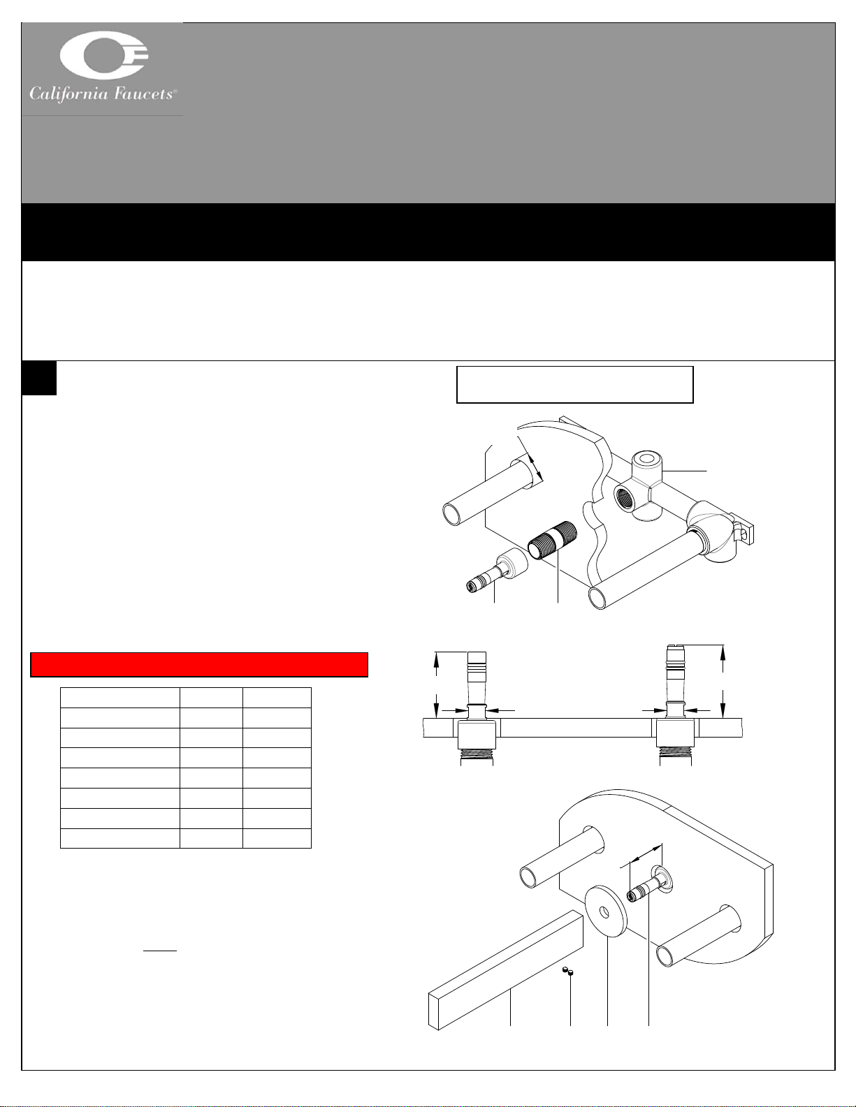
INSTALLING SPOUT
• Prior to installing faucet trim in-wall vessel rough
VALVE (1), must be properly installed and wall
surface must be completely finished
NOTE: Recommended through-hole size shall be Ø1-1/4”
• Apply thread sealant to both threaded ends of
NIPPLE (2), not supplied, and tighten into center
outlet of VALVE (1)
• Tighten QUICK CONNECT (3) onto end of
NIPPLE (2) using ½” open-end wrench
• Confirm QUICK CONNECT (3) is protruding from
finished wall the correct amount with table given
Model
MIN “A”
MAX “A”
CF-TO-VE302-7
1-11/16”
1-7/8”
CF-TO-VE302C-7
1-13/16”
1-15/16”
CF-TO-VE302C-7-77R
1-13/16”
1-15/16”
TS-E3-E3
1-9/16”
1-3/4”
D-E3-E3
1-9/16”
1-3/4”
TS-E3-77
1-11/16”
1-13/16”
D-E3-77
1-11/16”
1-13/16”
• Slide SPOUT ESCUTCHEON (4) onto QUICK
CONNECT (3)
IMPORTANT: To prevent damage to internal o-ring on SPOUT (5),
QUICK CONNECT (3) MUST be free of any dirt and/or debris
• Slide SPOUT (5) onto QUICK CONNECT (3) and
tighten both SETSCREW (5a) on bottom side of
SPOUT (5)
NOTE: If SPOUT ESCUTCHEON (4) is square, be sure to align it
with SPOUT (5)
CALIFORNIA FAUCETS RECOMMENDS THAT ALL PLUMBING PRODUCTS BE INSTALLED
BY A LICENSED PROFESSIONAL
NOTE: Spout installation shown with lavatory
vessel valve, Tub Spout installation is the same
A 3 4
5a
5
Ø1-1/4”
1 2 3
A
Tighten with
½” open-end wrench
A
For Tub Spout
For Lavatory Vessel
WARNING: Dimension “A” must be met to prevent water damage
CF-TO-VE302-7_ii_190422 Pg 2
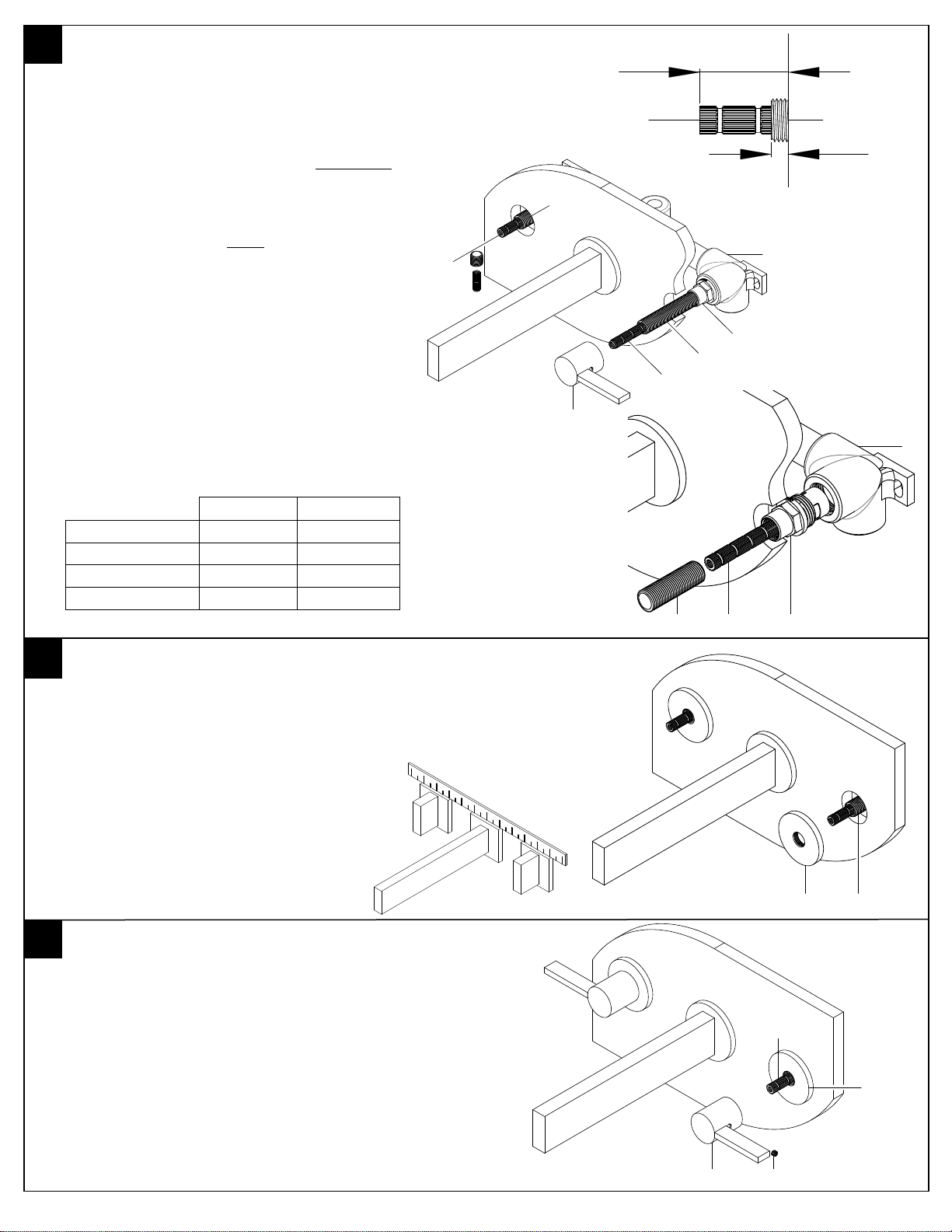
v ALIGN & TRIM VALVE STEM
• Remove mudguards from VALVE (1)
• To obtain proper HANDLE (7) alignment it may be
necessary to re-align cartridge STEM (1b); to align
STEM (1b), slightly loosen the cartridge NUT (1d),
place HANDLE (7) on STEM (1b) and TIGHTEN
in CW direction until desired alignment is achieved;
retighten cartridge NUT (1d) to factory torque
setting of 14 ft-lbs.
WARNING: Cartridge NUT (1d) MUST be properly torqued to
prevent possible failure and/or water damage
• Using a pencil/marker indicate a distance from
finished wall on ALL-THREAD (1c) (find distance in
column “MIN “C”” of table)
• Unscrew ALL-THREAD (1c) from valve STEM (1b)
• Cut STEM (1b) from finished wall surface according
to table (find distance in column “MIN “B”” of
table)
• Cut off excess ALL-THREAD (1c) at indicated mark
and reattach ALL-THREAD (1c) onto valve STEM
(1b) – repeat on other side
INSTALLING ESCUTCHEON
• Tighten handle ESCUTCHEON (6) onto ALL-
THREAD (1c)
NOTE: for VE302C-7 & VE302C-7-77R
• Tighten handle ESCUTCHEON (6) until it is secure
and aligned with spout; use ruler or straight edge to
confirm alignment
INSTALLING HANDLE
• Loosen SETSCREW (7a)
• Slide HANDLE (7) down onto and engage valve
STEM (1b) leaving a space of 1/32” between handle
and handle ESCUTCHEON (6)
• Tighten SETSCREW (7a)
• Turn on water supply and check for leaks
STEM
ALL-THREAD
Model
MIN “B”
MIN “C”
CF-TO-VE302-7
1-1/8”
3/16”
CF-TO-VE302C-7
1-1/4”
5/16”
CF-TO-VE302C-7-77R
1-1/4”
5/16”
californiafaucets.com 5271 Argosy Ave. Huntington Beach, CA 92649 800-822-8855
1b
7a 7 6
1c 6 B C 1c
1b 7 1b
1c
1d (13/16” hex)
1
1c
1b 1 1d
1b
1c
 Loading...