

California Faucets TO-THC1-XX User Manual
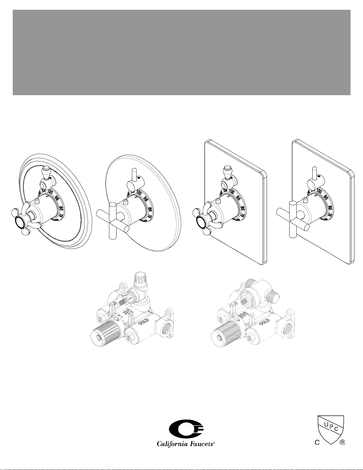
½” Thermostatic Valve with Single Volume Control Trim
TO-TH1-XX & TO-THC1-XX
StyleTherm™
Installation Instructions
TH51-R
(ROUGH)
TO-TH1-XX_ii_130102.doc Pg 1
TH51D2-R
(ROUGH)
CALIFORNIA FAUCETS RECOMMENDS THAT ALL PLUMBING PRODUCTS BE INSTALLED BY
A LICENSED PROFESSIONAL
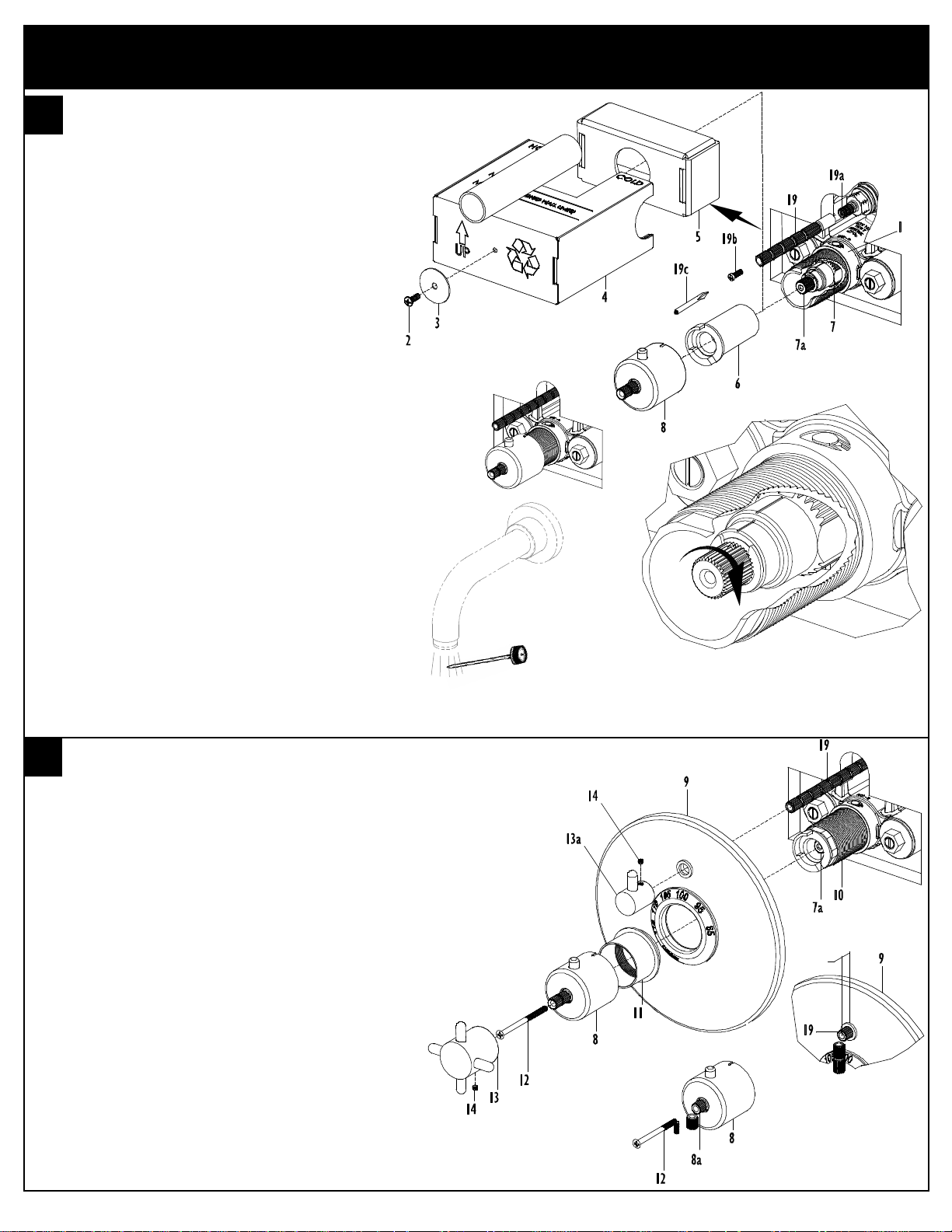
TEMPERATURE SETTING
• Remove SCREW (2), WASHER (3), MUDGUARD
(4) and SLEEVE (5) from installed VALVE (1)
• Push plastic TEMPERATURE LIMIT STOP (6) onto
THERMOSTATIC CARTRIDGE (7) as shown
• Temporarily place BONNET (8) onto
THERMOSTATIC CARTRIDGE STEM (7a)
• Place STEM (19) onto STOP/VOLUME CONTROL
(19a) and using PHILLIPS SCREWDRIVER (19C)
secure STEM (19) with SCREW (19b)
• With both hot and cold water supplies on, open
STOP/VOLUME CONTROL (19) valve to one
output device
• Use temperature measuring device to confirm
temperature is 100°F when BONNET (8) button is
positioned straight up at 12 o’clock
• When button on BONNET (8) is depressed and
rotated full left (CCW), the maximum temperature
discharged from valve will be 115°F (Note: Follow
all applicable local plumbing codes when setting
maximum discharge water temperature)
• Carefully remove BONNET (8) and place aside
until trim is installed
Note: If temperature is not 100°F with BONNET (8), button at 12
o’clock, the CARTRIDGE STEM (7a) must be rotated to change
temperature setting (clockwise (CW) for cooler & counter-clockwise
(CCW) for warmer)
WARNING: Forcibly rotating thermostatic cartridge stem prior to
installing handle trim, will damage cartridge and void warranty
INSTALL TRIM
• Position FACEPLATE (9) onto CARTRIDGE NUT
(10) as shown
• Install SLEEVE (11) onto CARTRIDGE NUT (10)
and tighten to secure FACEPLATE (9) against
shower wall
• Place BONNET (8) onto THERMOSTATIC
CARTRIDGE STEM (7a)
• Secure BONNET (8) with SCREW (12)
• Place HANDLE (13) onto BONNET (8) and
tighten handle SETSCREW (14)
Note: Depending on handle style, it may be necessary to cut
BONNET STEM (8a) and SCREW (12) to allow HANDLE (13) to
fully seat against BONNET (8)
100°F
Rotate CW for Cooler (shown)
Rotate CCW for Warmer
½”
• Cut VOLUME CONTROL STEM (19), ½” from
surface of FACEPLATE (9)
• Place VOLUME CONTROL HANDLE (13a) onto
VOLUME CONTROL STEM (19) and tighten
SETSCREW (14)
TO-TH1-XX_ii_130102.doc Pg 2
 Loading...