

California Faucets StyleTherm TH52D2-R Installation Instructions Manual
TH52D2-R_ii_161005 Pg 1
StyleTherm™
TH52D2- R
½” Thermostatic Valve w/ Dual Non-Shared & Single Control Outlets
Installation Instructions
IMPORTANT: Read all instructions prior to installation and provide copy of instructions to consumer.
WARNING: This valve is factory set to deliver water at 100°F; however, it is the installer’s responsibility to verify correct temperature
setting to prevent risk on scalding or other severe injury prior to consumer use. The installer is responsible for adjusting maximum
temperature setting according to Thermostatic Rough and Thermostatic Trim Installation Instructions.
Operating Specifications:
Recommended Supply Pressure: 20 to 70 psi
*†
Recommended Hot Water Supply Temperature: 120 to 140°F ‡
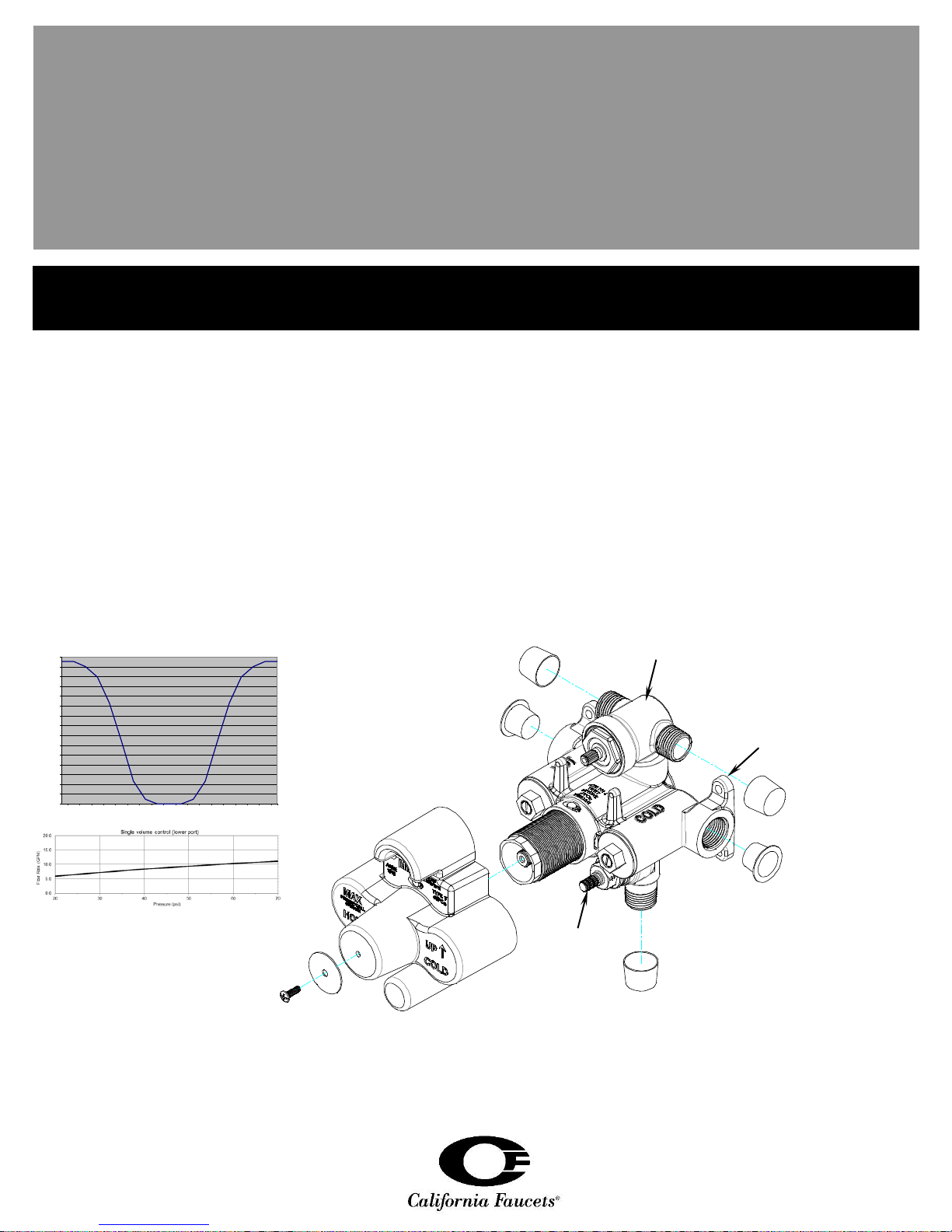
Nominal Flow Rate @ 60 psi (non-shared port): 7.2 gpm
Nominal Flow Rate @ 60 psi (lower port): 10.5 gpm
* Operating pressures between hot and cold supplies should vary no more than 30 psi.
† If water pressure exceeds 70 psi, install a Pressure-Reducing Valve (RPV).
‡ Follow all applicable local plumbing codes when setting the temperature on the water heater.
CALIFORNIA FAUCETS RECOMMENDS THAT ALL PLUMBING PRODUCTS BE INSTALLED
BY A LICENSED PROFESSIONAL
Body
Dual Non-Shared
Volume Control
Thread
Protector
Thread
Protector
Mudguard
Mudguard
Screw
Mudguard
Washer
Valve
Mounting Tab
0.0
0.5
1.0
1.5
2.0
2.5
3.0
3.5
4.0
4.5
5.0
5.5
6.0
6.5
7.0
7.5
0 10 20 30 40 50 60 70 80 90 100 110 120 130 140 150 160 170 180
Flow Rate (GPM) at 60 psi
Volume Control Lever Rotation
(0=full open RT, 90=closed & 180=full open LT)
Dual non-shared volume control (upper port)
Single Volume
Control
TH52D2-R_ii_161005 Pg 2
1
2
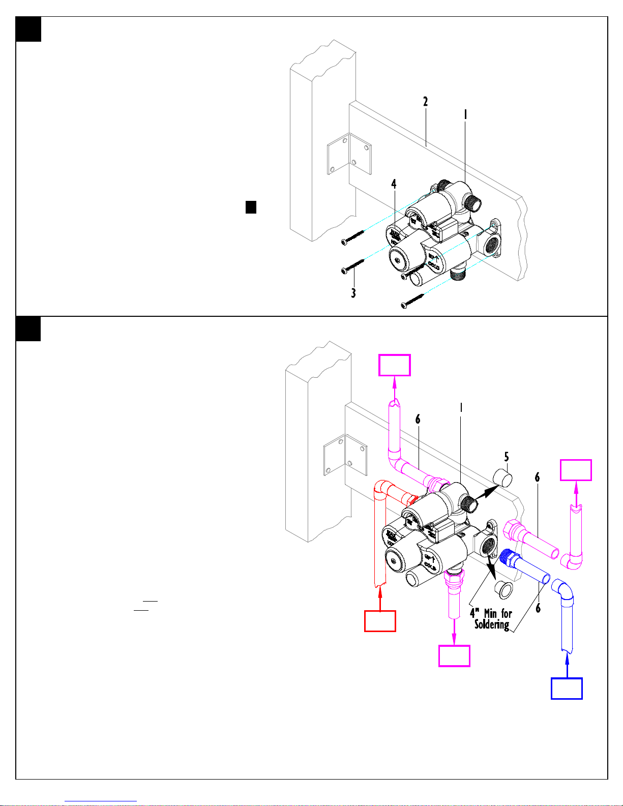
INSTALLING VALVE TO FRAME
Determine the desired location for the valve,
construct suitable stud, and support framing
Attach VALVE (1) to CROSS SUPPORT (2) by using
SCREWS (3) (not supplied) as shown
The valve should be level in HORIZONTAL,
VERTICAL and PARALLEL to wall
Placement of VALVE (1) and CROSS SUPPORT (2)
within the wall shall be determined by the MIN/MAX
Limits shown on MUDGUARD (4)
For complete detailed VALVE (1) dimensions see .5.
ROUGH-IN DIMENSIONS
WATER CONNECTIONS
Remove and discard THREAD PROTECTORS (5)
Pre-assemble FITTINGS (6) prior to attaching to
VALVE (1)
Apply thread sealant to all FITTING (6) threads and
attach to VALVE (1) Attach “COLD” INLET to
COLD SUPPLY and “HOT” INLET to HOT
SUPPLY. All soldering of FITTINGS (6) shall be
performed a minimum of 4” away from
VALVE (1)
Perform all other required connections to output
device(s) (i.e. showerhead, handshower, etc.…)
Turn on water supply and check for leaks
IMPORTANT: Flush supply lines prior to installation to prevent
damage and malfunction of thermostatic cartridge.
IMPORTANT: Cold water supply must be connected to inlet marked
“COLD” and hot water supply must be connected to inlet marked
“HOT”.
CAUTION: This valve contains plastic and rubber components. Do
not sweat or braze directly to the valve body. Do not apply excessive
heat to the valve body when performing solder connections. Do not
apply flux or acids directly to the valve, as damage to the seals, plastic
components, and trim finish may result.
CAUTION: Inlet and outlet threaded joint connections should be
made with plumber’s PTFE tape or liquid sealant. Oil-based, non-setting
compounds should not be used.
WARNING: Forcibly rotating thermostatic cartridge stem prior to
installing handle trim, will damage cartridge and void warranty.
HOT
SUPPLY
COLD
SUPPLY
MIXED
OUT
MIXED
OUT
MIXED
OUT
 Loading...