

California Faucets Solima Roman Set and Handshower with Trim User Manual
Solimar™
7008 & 70.1
Roman Tub Set and Handshower with Trim
Installation Instructions
1
CALIFORNIA FAUCETS RECOMMENDS THAT ALL PLUMBING PRODUCTS BE INSTALLED
BY A LICENSED PROFESSIONAL
Ø1-1/4”
IMPORTANT: Read all instructions prior to installation and provide copy of instructions to consumer.
Operating Specifications:
Recommended Supply Pressure: 20 to 70 psi
Maximum Flow Rate: 15 gpm
* Operating pressures between hot and cold supplies should vary no more than 30 psi.
† If water pressure exceeds 70 psi, install a Pressure-Reducing Valve (RPV).
*†
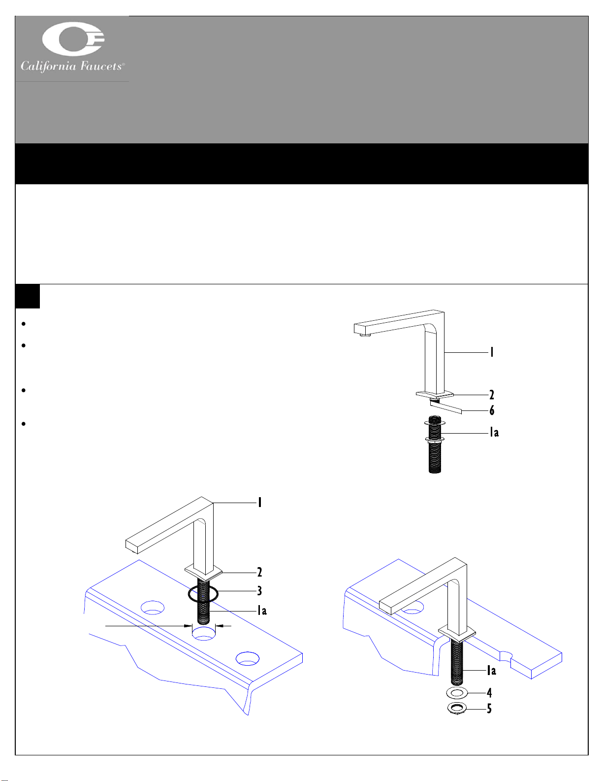
INSTALLING SPOUT
Tub/Deck recommended hole size shall be Ø1-1/4”
Apply Teflon
portion of SPOUT (1) and securely tighten SHANK
(1a) to SPOUT (1)
Place O-RING (3) into BASE (2) and insert spout
SHANK (1a) though deck hole
From underside place WASHER (4) onto spout
SHANK (1a) and secure SPOUT (1) in place with
NUT (5)
7008_ii_140505.doc Pg 1
®
tape (6) (not supplied) to threaded
2 3 4
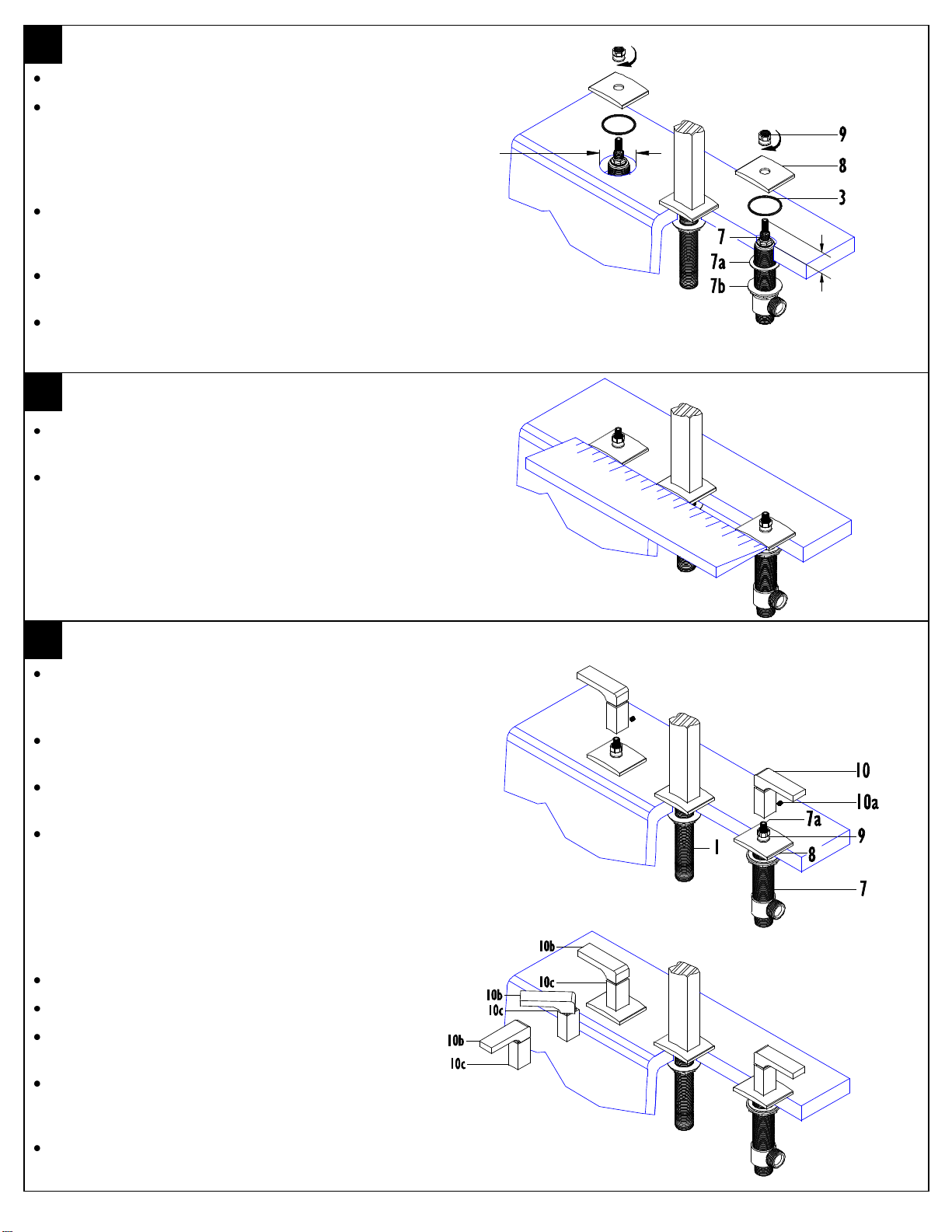
INSTALLING VALVE
1-3/8”
Ø1-1/4”
Tub/Deck recommended hole size shall be Ø1-1/4”
From underside insert VALVE (7) though
appropriate tub/deck hole
IMPORTANT: VALVES (7) are labeled as follows:
BLUE is COLD left turning (counter-clockwise) closed
RED is HOT right-turning (clockwise) closed
Position flange NUT (7b) and WASHER (7a) so
that VALVE (7) extends 1-3/8” above tub/deck
surface
Insert O-RING (3) into ESCUTCHEON (8) and
place onto VALVE (7)
Secure ESCUTCHEON (8) onto tub/deck by
tightening lock NUT (9)
ALIGNMENT OF BASES
Use a ruler or straight edge to align the spout base
and escutcheons of the faucet as shown
After alignment retighten lock nuts and spout nut
INSTALLING HANDLE
Loosen SETSCREW (10a) from HANDLE (10)
IMPORTANT: Handle BLADE (10b) shall be aligned with wider
portion of handle POST (10c)
Slide HANDLE (10) down onto and engage valve
STEM (7a)
Handle POST (10c) shall completely cover lock
NUT (9) and seat against ESCUTCHEON (8)
Tighten SETSCREW (10a) and rotate handle
BLADE (10b) to check operation, open position is
when BLADE (10b) is rotated forward
To obtain proper alignment it may be necessary to
rotate VALVE (7) so that handle BLADE (10b) is
aligned with SPOUT (1). This may be achieved as
follows:
Slightly loosen lock NUT (9)
Place HANDLE (10) onto valve STEM (7a)
Rotate VALVE (7) in proper direction to achieve
proper alignment of handle BLADE (10b)
Remove HANDLE (10) and while firmly holding
VALVE (7) in position from underneath securely
tighten lock NUT (9)
Then reattached HANDLE (10) as mentioned
above
7008_ii_140505.doc Pg 2
 Loading...