

California Faucets Solimar CF-TO-V7002-9 Installation Instructions Manual
CF-TO-V7002-9_ii_160720 Pg 1
Solimar™
CF-TO-V7002-9
In-Wall Vessel Lavatory Faucet
Installation Instructions
1
IMPORTANT: Read all instructions prior to installation and provide copy of instructions to consumer.
Operating Specifications:
Recommended Supply Pressure: 20 to 70 psi
*†
Maximum Flow Rate: 1.2 gpm
* Operating pressures between hot and cold supplies should vary no more than 30 psi.
† If water pressure exceeds 70 psi, install a Pressure-Reducing Valve (RPV).
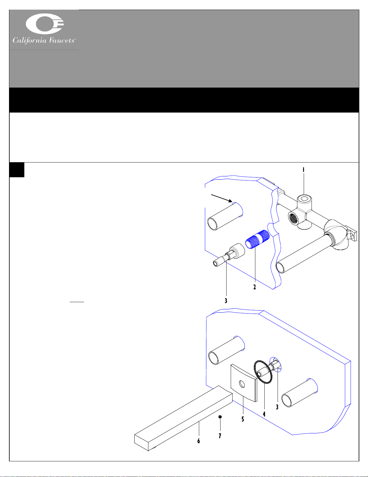
INSTALLING SPOUT TO IN-WALL VALVE
Prior to installing faucet trim in-wall vessel rough
VALVE (1), CF-VL-R, must be properly installed
and wall surface must be completely finished
Recommended through-hole size shall be Ø1-1/4”
Apply thread sealant to both threaded ends of
NIPPLE (2), not supplied, and tighten into center
outlet of VALVE (1)
Securely tighten QUICK CONNECT (3) onto end
of NIPPLE (2) using I/2” open-end wrench
Place O-RING (4) into ESCUTCHEON (5) & slide
ESCUTCHEON (5) onto QUICK CONNECT (3)
IMPORTANT: To prevent damage to internal o-ring on SPOUT
(6), QUICK CONNECT (3) MUST be free of any dirt and/or debris
Slide SPOUT (6) onto QUICK CONNECT (3),
align ESCUTCHEON (5) & SPOUT (6) and tighten
SETSCREW (7) on bottom side of SPOUT (6)
CALIFORNIA FAUCETS RECOMMENDS THAT ALL PLUMBING PRODUCTS BE INSTALLED
BY A LICENSED PROFESSIONAL
Ø1-1/4”
(3 holes)
CF-TO-V7002-9_ii_160720 Pg 2
2
3
4
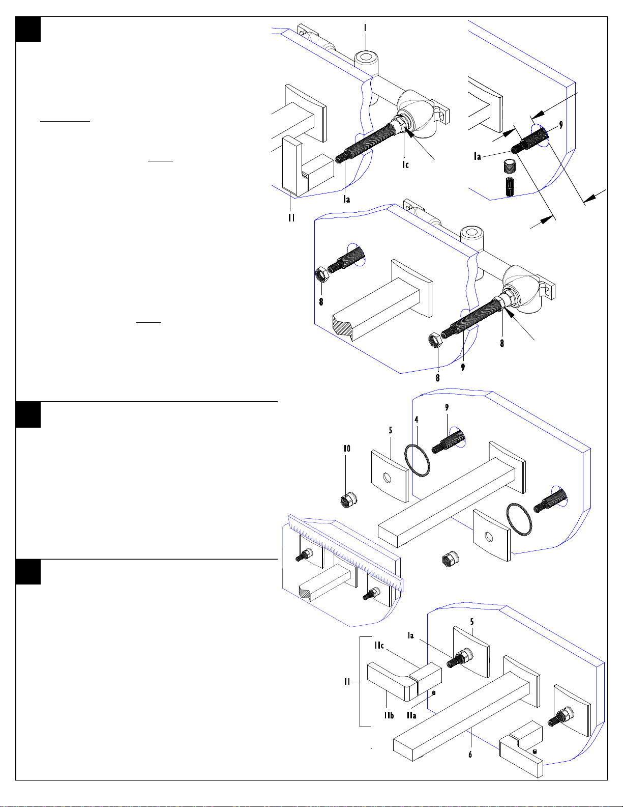
v ALIGN & TRIM VALVE STEM
Remove MUDGUARD (1b) from VALVE (1)
To obtain proper HANDLE (11) alignment it may
be necessary to re-align cartridge STEM (1a); to
align STEM (1a), slightly loosen the cartridge NUT
(1c), place HANDLE (11) on STEM (1a) and
TIGHTEN in CW direction until desired
alignment is achieved; retighten cartridge NUT (1c)
to factory torque setting of 14 ft-lbs.
WARNING: Cartridge NUT (1c) MUST be properly torqued to
prevent possible failure and/or water damage
Unscrew ALL-THREAD (9) from valve STEM (1a)
Cut STEM (1a) 1-3/8” from finished wall surface
Reattach ALL-THREAD (9) onto valve STEM (1a),
using a marking device (e.g. pencil or marker)
indicate a distance of ¾” from finished wall on ALLTHREAD (9); remove ALL-THREAD (9) and cut off
excess ALL-THREAD (9) at indicated mark &
reattach ALL-THREAD (9) onto valve STEM (1a) –
repeat on other side
IMPORTANT: To prevent HANDLE (11) rotation during operation
of faucet set LOCK-NUT (8) MUST be placed on both ALL-
THREAD (9) of VALVE (1)
Place LOCK-NUT (8) onto ALL-THREAD (9) and
tighten against cartridge NUT (1c) to prevent ALLTHREAD (9) from rotating while operating
HANDLE (11) – repeat on other side
INSTALLING ESCUTCHEON
Insert O-RING (4) into ESCUTCHEON (5) and
place onto ALL-THREAD (9)
Secure ESCUTCHEON (5) onto wall by tightening
lock NUT (10)
To align ESCUTCHEONS (5), use a ruler or
straight edge to align the spout and handle
escutcheons of the faucet as shown; after alignment
retighten lock NUTS (10)
INSTALLING HANDLE
Loosen SETSCREW (11a) from POST (11c)
IMPORTANT: Handle BLADE (11b) shall be aligned with wider
portion of handle POST (11c)
Slide HANDLE (11) down onto and engage valve
STEM (1a)
Handle POST (11c) shall completely cover lock
NUT (10) and seat against ESCUTCHEON (5)
Tighten SETSCREW (11a) and rotate handle
BLADE (11b) to check operation, open position is
when BLADE (11b) is rotated upward – repeat on
other side
1-3/8”
californiafaucets.com 5271 Argosy Ave. Huntington Beach, CA 92649 800-822-8855
13/16”
hex
3/4”
11/16”
hex
 Loading...