

Page 1
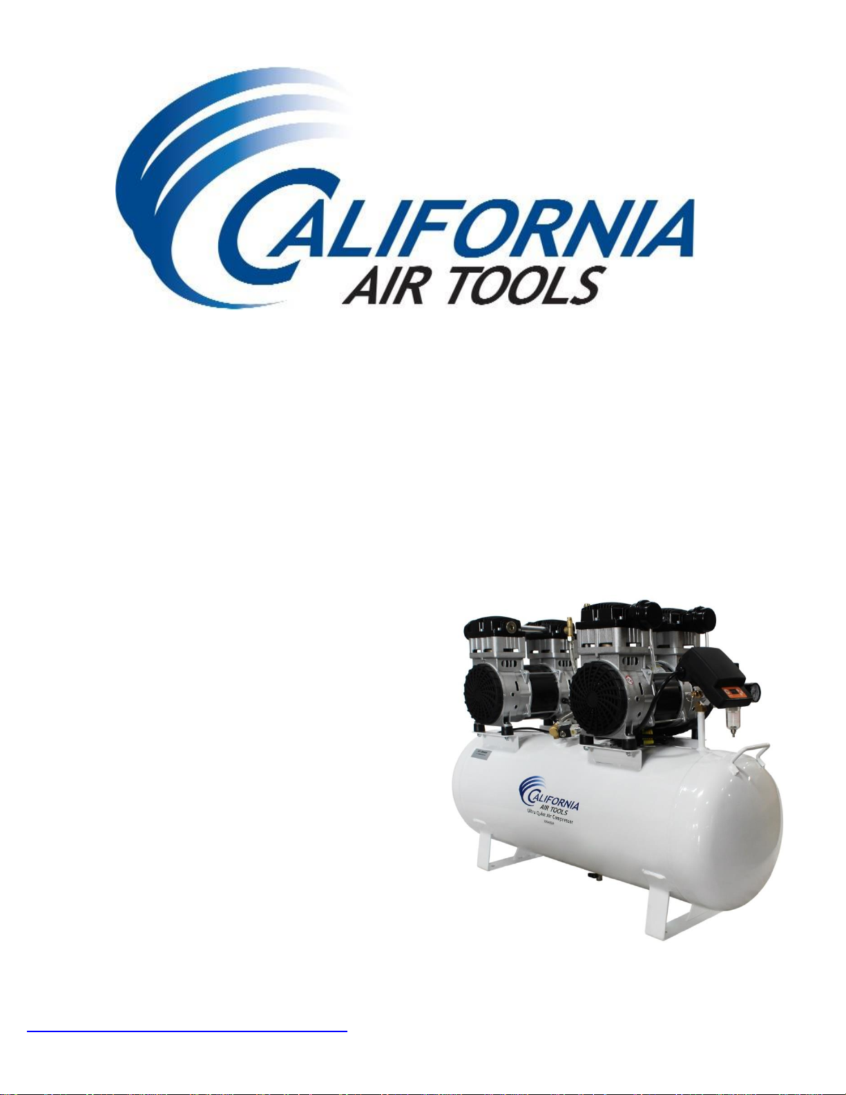
ULTRA QUIET & OIL FREE
SMART AIR COMPRESSOR
OWNER'S MANUAL
CALIFORNIA
AIR TOOLS
20040SM
4.0 HP 220V 60HZ 1-PHASE
12.80 CFM @ 40 PSI -- 10.6 CFM @ 90 PSI
20.0 GA LLON STEE L TANK
SMART CONTROLLER
WWW.CALIFORNIAAIRTOOLS.COM Customer Support 1-866-409-4581
Page 2
AIR COMPRESSOR
2
Customer Support: 1-866-409-4581
TABLE OF CONTENTS
INTRODUCTION __________________________________ 2
IMPORTANT SAFETY INSTRUCTIONS _______________ 3
LOCATIONS OF IMPORTANT LABELS _______________ 6
AIR COMPRESSOR COMPONENTS _________________ 7
PRE-OPERATION CHECKLIST ______________________ 9
Package Contents & Assembly ___________________ 9
Inspect for Damage ____________________________ 10
Save Packaging _______________________________ 10
Compressor Location __________________________ 10
Electrical Power _______________________________ 11
OPERATING THE AIR COMPRESSOR ______________ 11
Introduction __________________________________ 11
Assembly ____________________________________ 11
Test Run _____________________________________ 12
Daily Operation _______________________________ 13
MAINTENANCE _________________________________ 15
Draining the Air Tank __________________________ 15
Changing the Air Filter _________________________ 15
Testing for Leaks ______________________________ 15
SMART Controller Features _____________________ 15
Cleaning _____________________________________ 15
STORAGE _____________________________________ 16
TROUBLESHOOTING ____________________________ 17
SPECIFICATIONS _______________________________ 18
Electrical Circuit ______________________________ 18
Air Passage Drawing ___________________________ 18
WARRANTY ____________________________________ 19
INTRODUCTION
Thank you for purchasing a California Air Tools, Inc.
Air Compressor.
Please contact us if you have any questions.
Record the model and serial numbers indicated on your
air compressor’s nameplate:
Model No.
Serial No.
Date of Purchase:
Store/Dealer:
Page 3
AIR COMPRESSOR
Customer Support: 1-866-409-4581
3
How to find a local service center:
Even quality built equipment might need service or repair parts.
Contact the California Air Tools Customer Service Department:
Phone: 1-866-409-4581
Online: WWW.CALIFORNIAAIRTOOLS.COM
Please provide the information below:
Model number and Serial number and specifications shown on
the Model number/Serial number plate.
Part number or numbers shown in the parts list section of the
owner’s manual for your air compressor model.
A brief description of the trouble with the air compressor.
Do not return your air compressor for service or parts to the
store/dealer where purchased.
IMPORTANT SAFETY
INSTRUCTIONS
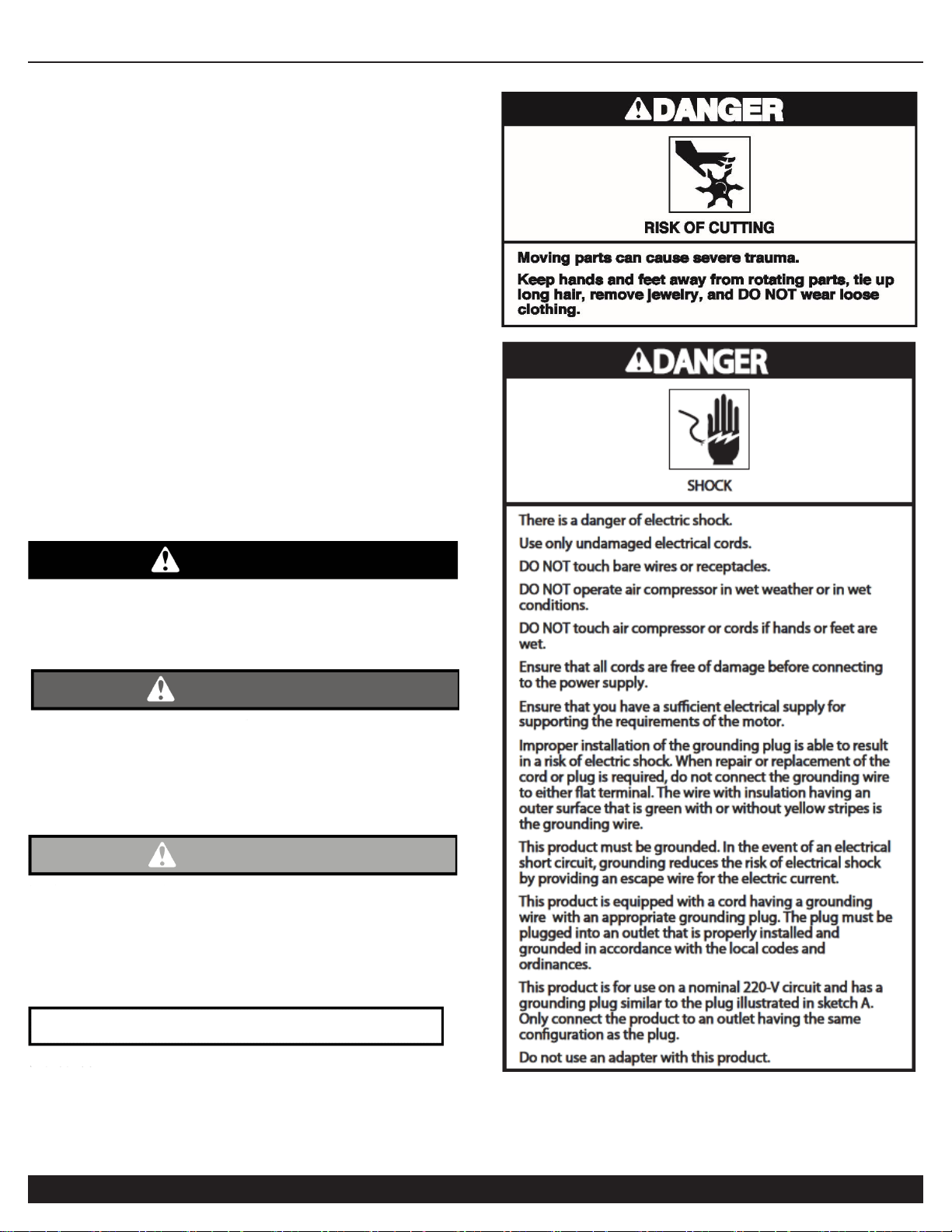
Safety Messages & Signal Words:
Indicates an immediate hazardous situation which, if not
avoided, will result in death or serious injury to the
operator or to bystanders.
DANGER
WARNING
Indicates a potentially hazardous situation which, if not
avoided, could result in death or serious injury to the
operator or to bystanders.
CAUTION
Indicates a potentially hazardous situation which, if not
avoided, may result in moderate or minor injury to the
operator or to bystanders.
Indicates a situation which, if not avoided, may result in
damage to product components or other property.
NOTICE
Page 4
AIR COMPRESSOR
4
Customer Support: 1-866-409-4581
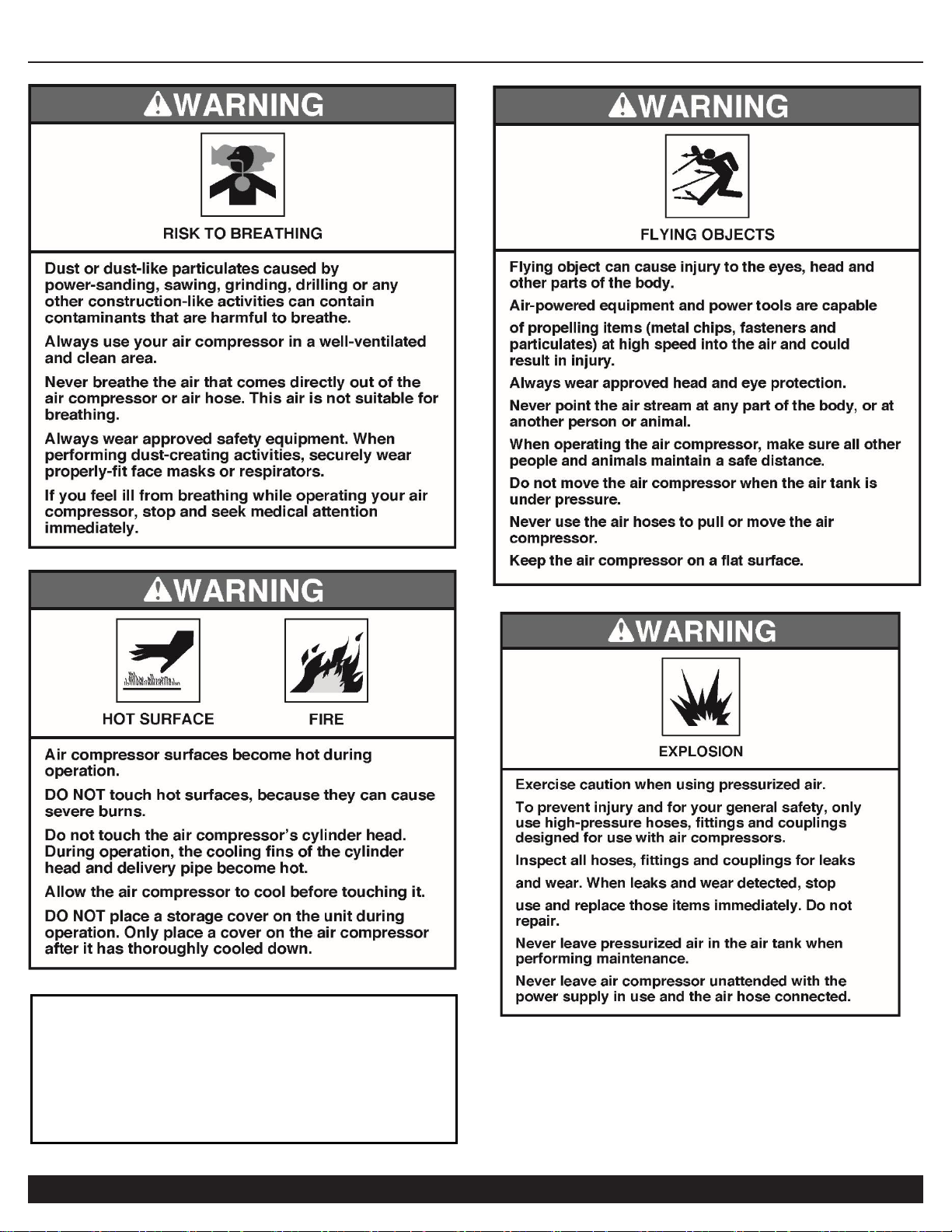
NOTE: The compressor is designed for intermediate
usage and should not be allowed to run continuously
(i.e. where motor/pump continuously runs) for more
than 60 minutes at a time. Intermediate ON/OFF
usage during a standard workday is acceptable with
an average 70/30 operating duty cycle.
Page 5
AIR COMPRESSOR
Customer Support: 1-866-409-4581
5
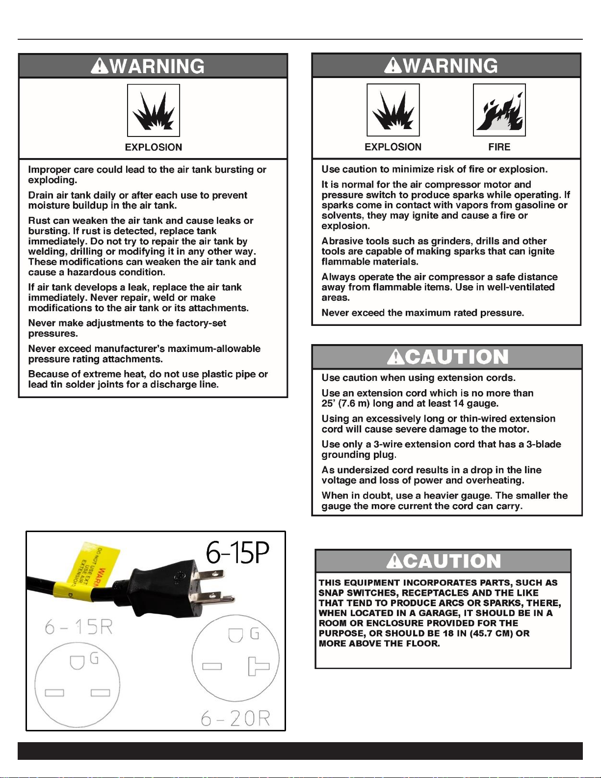
Power Requirements
• 220v 60hz 1-phase (215v – 250v range)
• 13-14 Amps (20 Amp breaker minimum
suggested)
• Included NEMA 6-15P plug (6 foot power
cable) may be connected to either a 6-15R
or 6-20R electrical receptacle.
Page 6
AIR COMPRESSOR
6
Customer Support: 1-866-409-4581
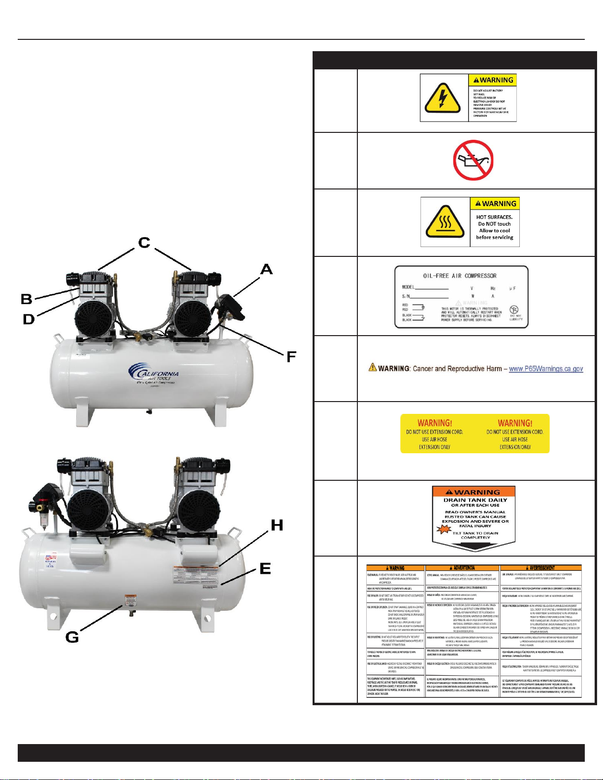
LOCATIONS OF
IMPORTANT LABELS
Read these important labels before operating.
These labels provide important safety and maintenance
information. These labels should be considered as permanent
parts of the air compressor. Should any of these labels become
illegible, damaged or removed, please contact California Air
Tools Customer Service department at 1-866-409-4581 for
replacements.
PRODUCT LABEL
A
B
C
D
E
F
G
H
Page 7
AIR COMPRESSOR
Customer Support: 1-866-409-4581
7
Page 8
AIR COMPRESSOR
8
Customer Support: 1-866-409-4581
Page 9
AIR COMPRESSOR
Customer Support: 1-866-409-4581
9
PRE-OPERATION CHECKLIST
Package Contents & Assembly
Model: 20040SM
Package contents:
Air Compressor
20040SM Owner’s Manual
MDR2i Smart Controller Owner’s Manual
Air Filters (4)
Air Filter Intake Tubes (4), 8mm OD
Assembly:
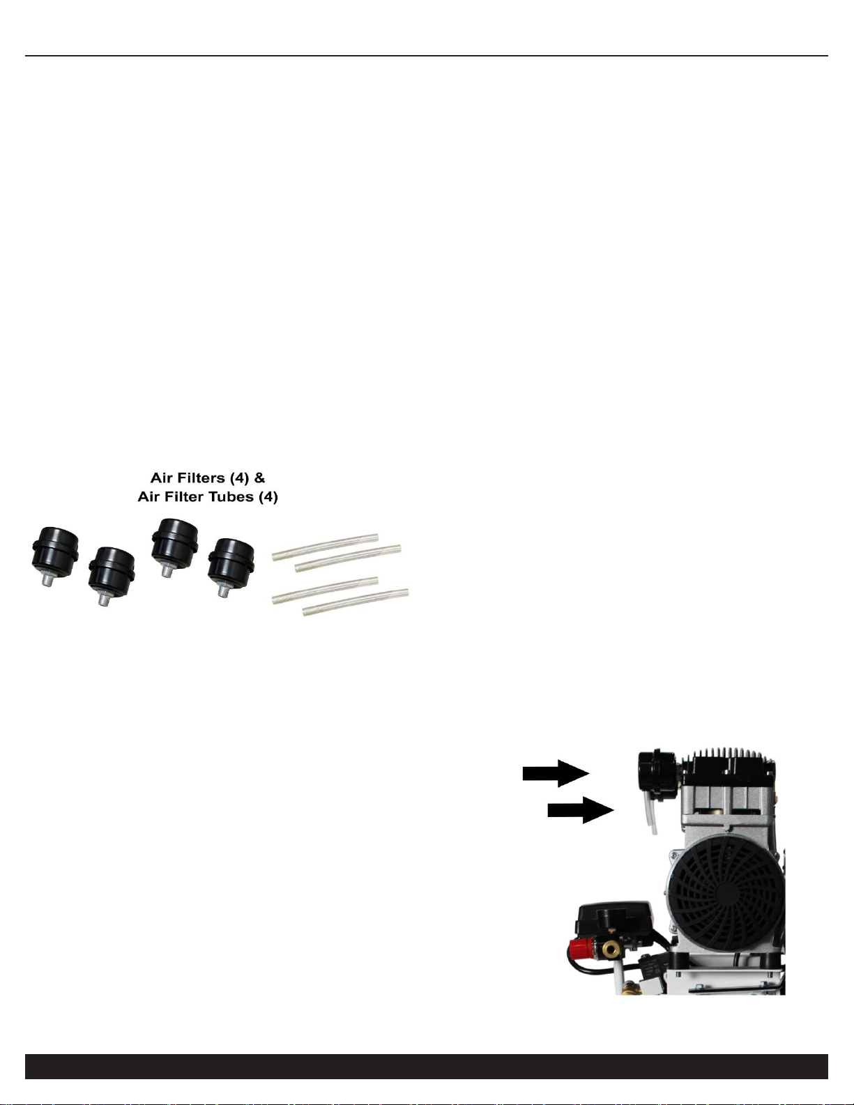
Install the 4 Air Filters and 4 Air Intake Tubes
1. Attach the air filters to the top rear sides of BOTH motor
head’s threaded ½” ports.
2. Screw the air filters clockwise until secure (hand tighten only).
Push (press fit) the 4” air filter intake tube into the air filter
port/hole (8mm OD). Repeat for the other intake tube.
Note: orientation of the intake tubes does not matter, they
may point any direction.
Air Filters (4)
& Air Filters Tube (4)
Page 10
AIR COMPRESSOR
10
Customer Support: 1-866-409-4581
Inspect for Damage
Before using the air compressor, make sure the air tank is not
damaged, inspect all parts for damage, and check that all
pipes are firmly connected.
Do not use the air compressor if any damage is found. If
damaged, have an authorized service center inspect and test
the air compressor to ensure that it is working properly.
Save Packaging
IMPORTANT: Save all outside packaging in case you ever
need to return the product for service or repair.
Compressor Location
Use on Flat Surface
For proper operation, the air compressor must be placed on a
flat surface with an incline no greater than 15 degrees. It is
suggested to secure the air compressor, by bolting down or
earthquake strapping, to prevent model from accidentally
falling over.
Maintain a Clear Area
It is very important that the air compressor is positioned so
that there is adequate airflow around the machine. There
must be at least 2 feet of obstacle-free space surrounding
and above the air compressor.
Use in Areas with Clean Air
For proper operation and to maximize the longevity of the
air compressor, it is very important that the air drawn into
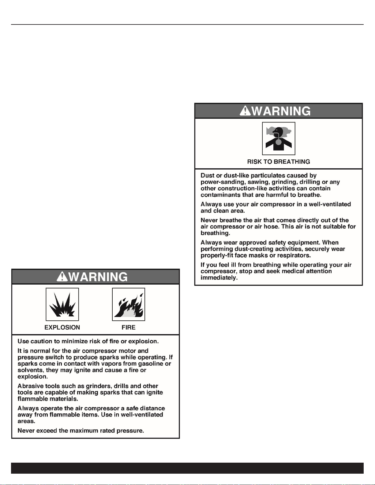
the air compressor is clean. The air compressor should not
be used in areas where dust or particulates are in the air.
This will damage the motor and impair proper operation.
IMPORTANT: Always use the air filter, properly installed.
Page 11
AIR COMPRESSOR
Customer Support: 1-866-409-4581
11
Electrical Power
Electrical Power Requirements
Before using the air compressor, refer to the serial label for
voltage and amperage requirements. Ensure there is a sufficient
electrical supply for supporting the motor's requirements.
Use a dedicated 20 Amp Circuit or a 8000 Watt (running)
Generator. Compressor requires 13-14 Amps for startup.
Low voltage and/or an overload circuit can cause the
motor's overload protection system circuit breaker to trip.
Use a dedicated 20 (or 25/30) Amp Circuit:
220 Volts 60 Hertz 1-Phase (acceptable operating range
215 volts to 240 volts).
Electrical Extension Cords
Inspect all electrical extension cords to ensure that they are
free of damage. When using an extension cord, use a heavyduty cord that is no more than 25 feet long and at least 14
gauge. Use only a 3-wire extension cord that has a 3-blade
grounding plug.
OPERATING THE AIR
COMPRESSOR
Save this manual for future reference.
Introduction
This air compressor features a compact structure, stable
performance, a high airflow rate, easy operation and
maintenance. Because the air compressor produces no oil in
the airflow, it can be used as an independent air supply
machine for situations in which oil in the airflow is an issue.
The motor directly drives the pistons and is able to function
without lubrication for a long period of time.
Assembly
1.
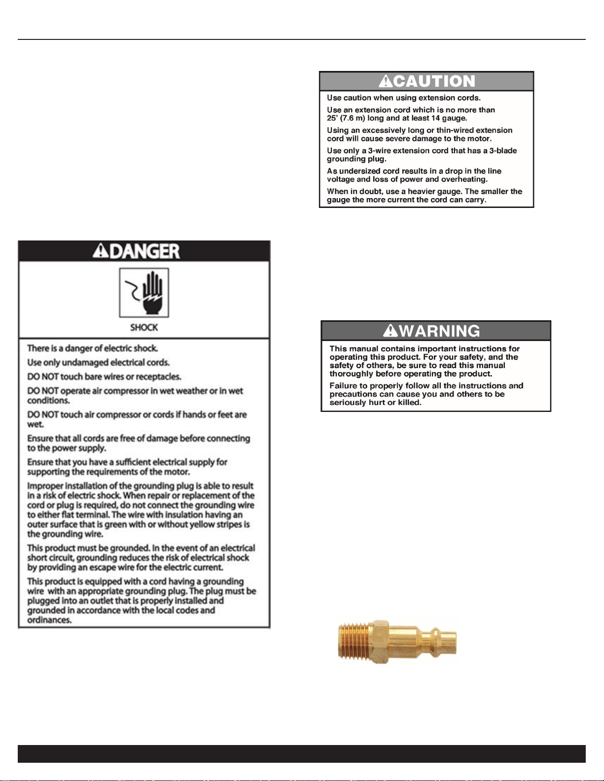
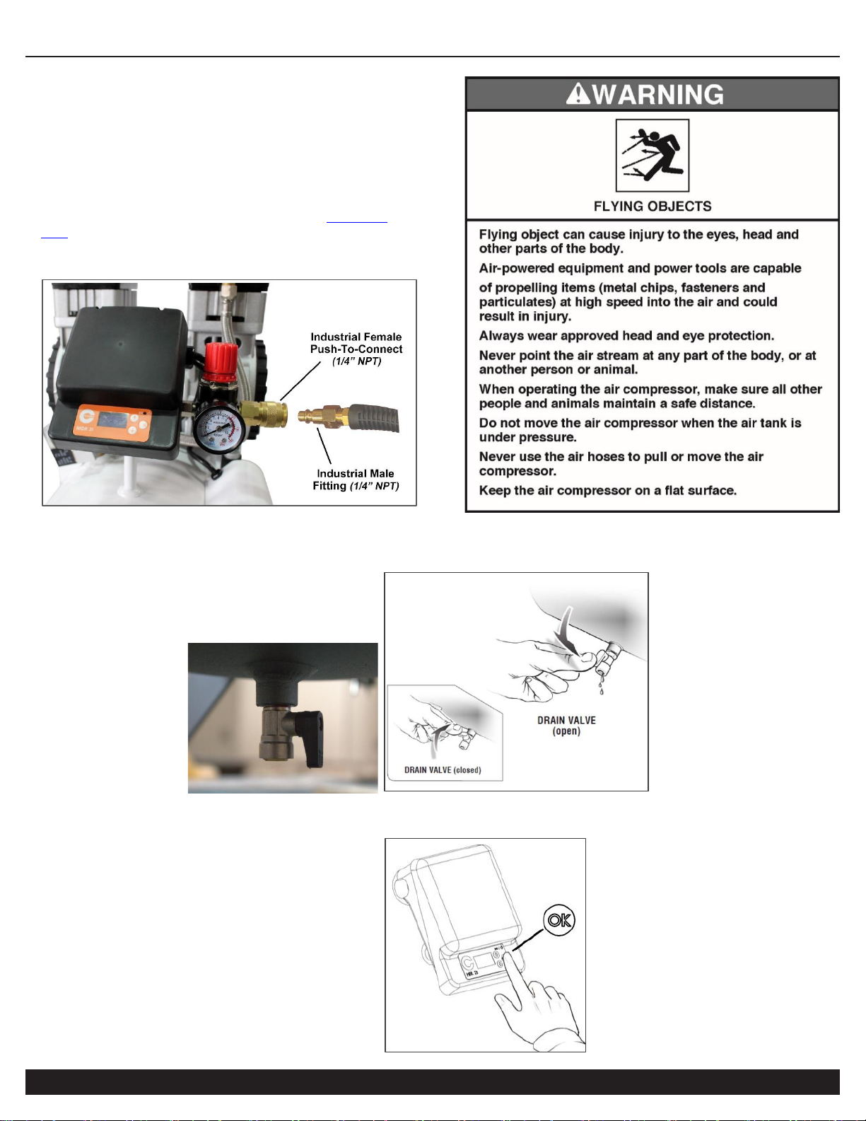
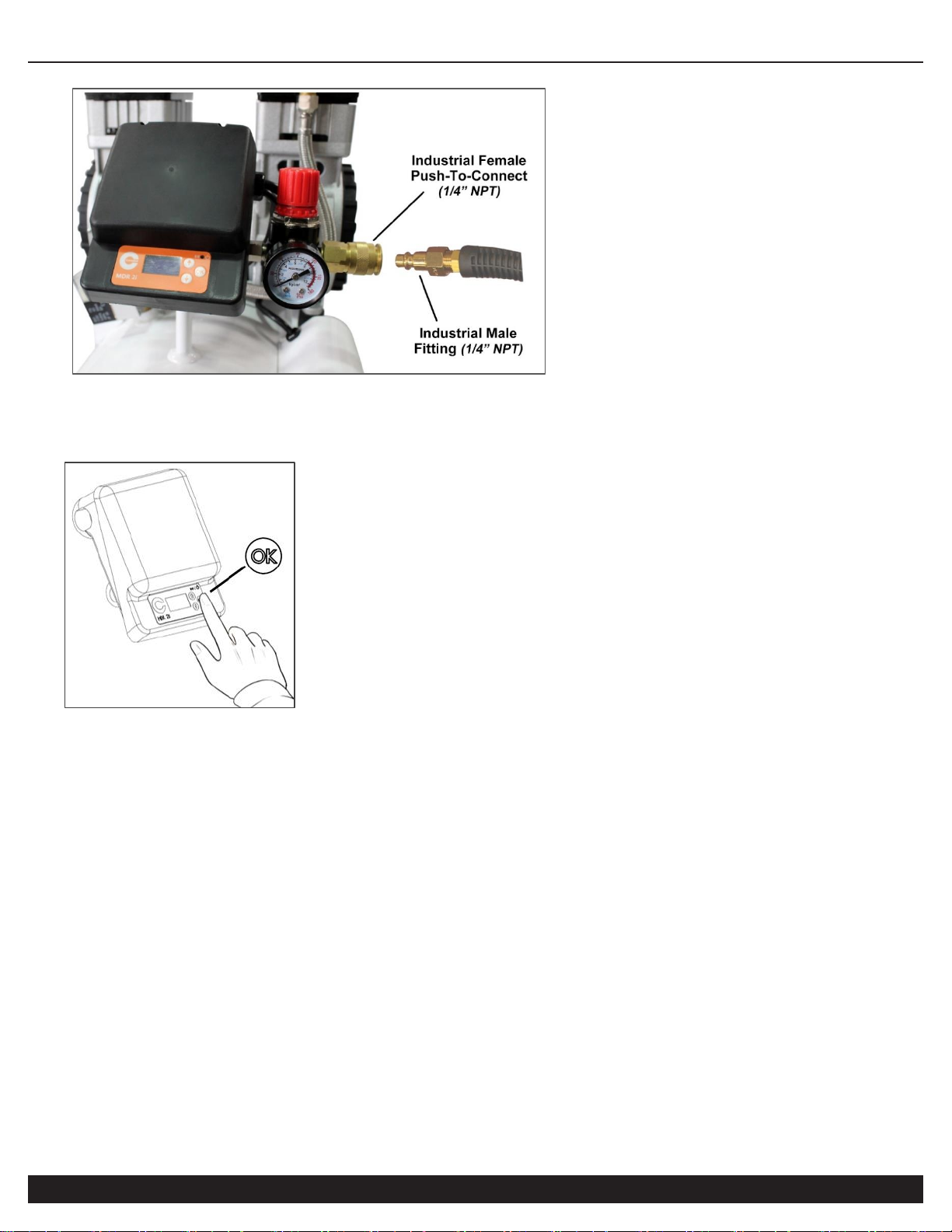
Connect an air supply hose [not supplied; featuring an
Industrial
Male
(1/4” NPT) adapter/couple (pictured below)], to the
Industrial Female (1/4” NPT) push-to-connect quick coupler on
air compressor. Also see page 12..
2. Ensure that the power supply you are going to use is
operating normally. 220 Volts 60 Hertz 20 Amp Outlet.
3. Insert the power supply cord into the power supply socket.
Page 12
AIR COMPRESSOR
12
Customer Support: 1-866-409-4581
Test Run
Before using the air compressor for the first time, complete a
test run as follows:
1. Plug the power supply cord into a 220 volt 60hz 1-phase
power supply socket (215v – 250v range).
2. Attach an air hose gun or pneumatic tool
(i.e. CAT-376
item; not supplied)
to the 1/4” Industrial Female Push-To-
Connect air port.
3. Ensure the Manual Ball Drain Valve, at bottom of tank, is closed
prior to turning the air compressor on (i.e. turned 90 degrees)
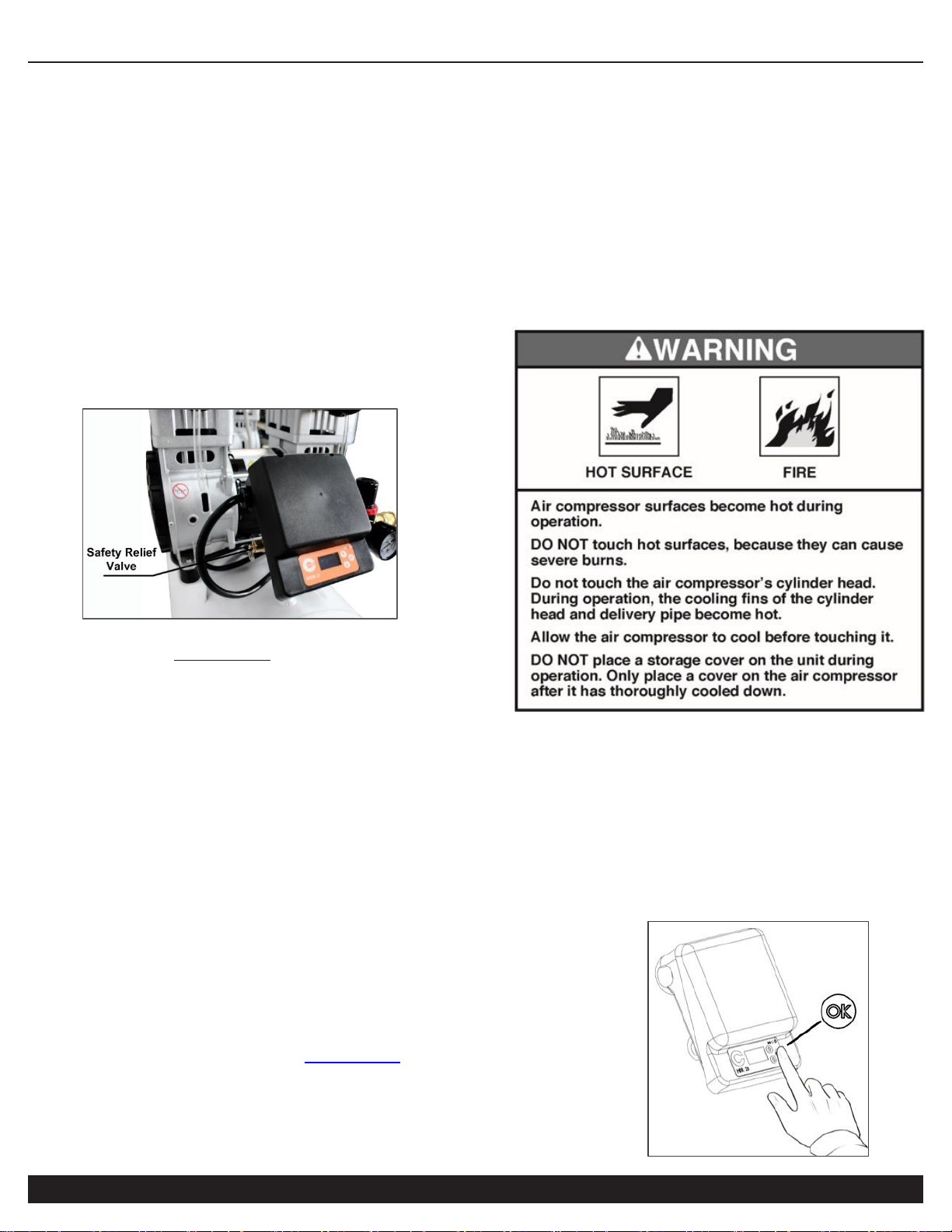
4. PRESS & HOLD the SMART switch OK button for 4
seconds to turn ON air compressor.
Page 13
AIR COMPRESSOR
Customer Support: 1-866-409-4581
13
5. Both Motor/pumps should start.
Pressure will slowly rise as pressure increases inside the
air tank. When the pressure reaches 120 PSI (+/- 5 PSI),
the Smart pressure switch will automatically turn the
motor/pumps power off. This indicates the compressor is
working normally.
NOTE: Working Pressure 90-120 PSI (+/-5 PSI).
Adjustable up to 105 PSI Kick-On; 130 PSI Kick-Off
maximum. Refer to Smart Controller Manual to adjust.
Unplug the power supply cord and release the air in the air
tank by either of the following methods:
a. Pull Safety Relief Valve ring to release air from tank.
Suggested for initial testing or emergencies only.
b. Expel air from compressor using connected Air Hose
Gun/Tool (i.e. CAT-376 item; not supplied). This is
the recommended discharge method for all regular &
daily air compressor operations.
Note: If there is an air leak from the compressor the
pressure in the air tank decreases, the Smart Controller
(pressure switch) resets and the motor automatically turns
back on.
If compressor fails to start or you detect an air leakage,
deactivate the air compressor and release the air from
the tank (if under pressure) – see Step 3 above. Unplug
the power supply cord and contact Customer Support for
Assistance.
DAILY OPERATION
Starting the compressor:
1. PRESS & HOLD the SMART switch OK button for 4 seconds
to turn OFF air compressor.
2. Attach an air hose gun or tool
(i.e. CAT-376 item; not supplied)
to the 1/4”
Industrial Female Push-To-Connect Air Port.
Page 14
AIR COMPRESSOR
14
Customer Support: 1-866-409-4581
3. Close Manual Ball Drain valve and ensure both air filters are attached to motor/pump.
4. Plug the power supply cord into a power supply socket.
5. PRESS & HOLD the SMART switch OK button for 4 seconds to turn ON.
6. Allow the two (2) motors run and tank fill until motor/pumps stop and turn off.
7. To regulate the air flow.
While the air compressor is running, turn “On” your tool and turn the regulator knob to the right increasing the pressure.
Turn the pressure up until the desired pressure is reached.
9. Operate air tool normally.
NOTE: Working Pressure 90-120 PSI (+/-5 PSI).
Adjustable up to 105 PSI Kick-On; 130 PSI Kick-Off
maximum.
Shutting down the compressor:
1. PRESS & HOLD the SMART switch OK button for 4 seconds to turn compressor OFF.
2. Unplug the power supply cord.
3. Remove the pressure and water in the air tank through manual drain valve (or alternatively using connected air hose
gun/kit or pneumatic tooling to release air pressure from tank).
Page 15
AIR COMPRESSOR
Customer Support: 1-866-409-4581
15
MAINTENANCE
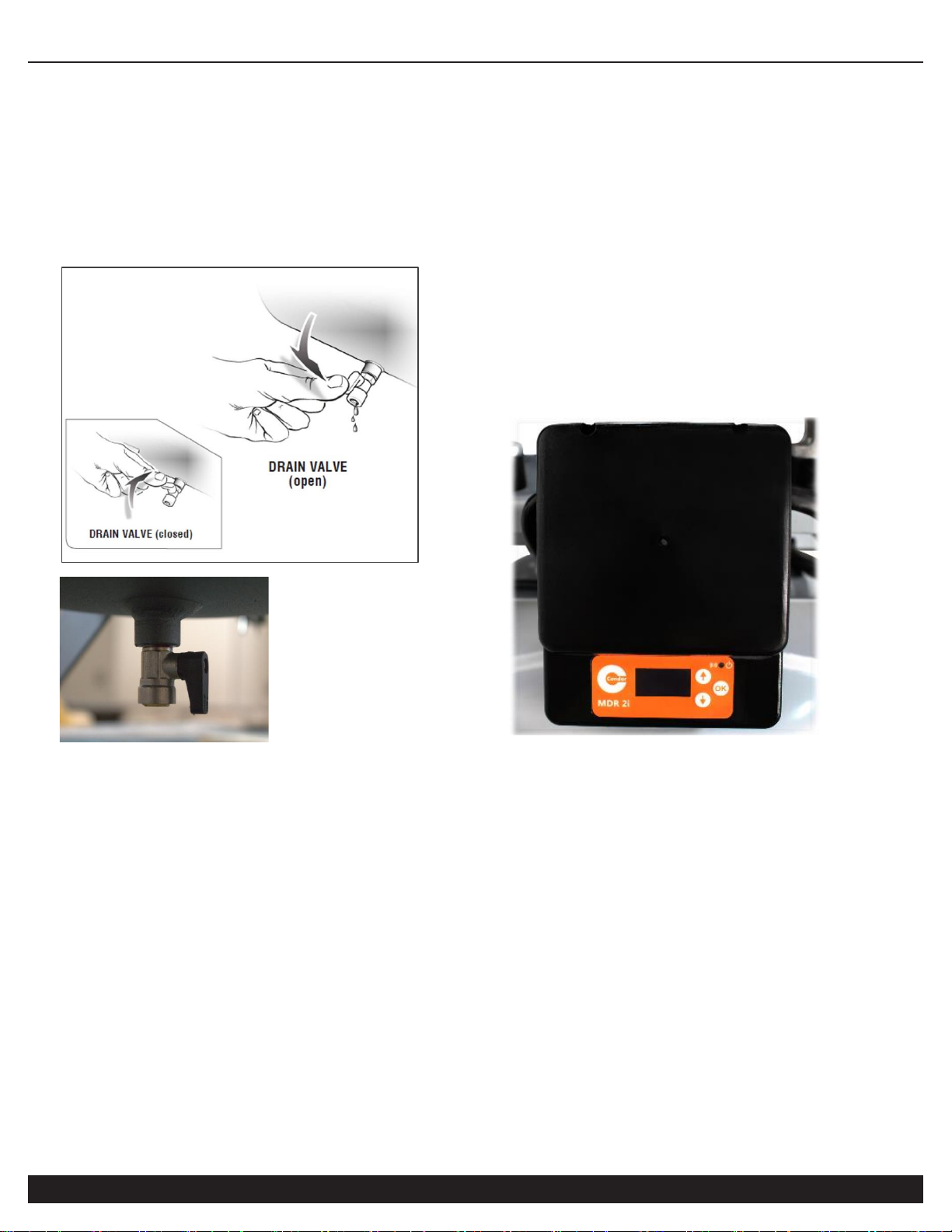
Remove Water from Tank Daily:
Turn the Manual Ball Drain Valve lever to be inline with
tubing; water/air will eject from valve opening. Close lever
(90 degree angle) when water is no longer draining/visible.
Cleaning or Changing the Air Filter
The air filter is designed to reduce noise and help prevent
particulates in the air from entering and damaging the air
compressor.
After being used for a period of time, the air filter will become
clogged. This will reduce the air intake capabilities of the air
compressor, reducing performance. Therefore, the air filter(s)
must be cleaned or replaced regularly.
1. Open the lid on the air filter, then remove the air filter
element.
2. To clean the element blow off or brush off the dirt and dust.
3. If clogged, replace with a new air filter.
Testing for Leaks
Make sure all connections are tight. Do not overtighten.
A small leak in any hose or pipe connection will reduce the air
compressor's performance.
To test for small leaks, spray a small amount of soapy water on
the area suspected of leaking. If the soap bubbles, replace the
broken part.
Cleaning
Clean items with a soft brush, or wipe with a moistened cloth
using a biodegradable solvent.
Do not use flammable liquids such as gasoline or alcohol. Always
keep parts clean from dirt and dust for better performance.
SMART Controller Features
MDR2i OLED Smart Pressure Switch for remote monitoring and
control. Refer to MDR 2i Smart Controller Manual.
• Programmable ON/OFF Times
• Pressure ON Level (i.e. re-start pressure)
• Pressure OFF Level (i.e. shutdown pressure)
• Unloader Relay Delay: Delay time for activation of the unloader
valves during compressor start-up (load reduction).
• AutoDrain Time: Select the time between each drain activation.
• Drain Valve Time: AutoDrain valve opening duration.
• Overcurrent Limit: (i.e. functions as an electrical trip/breaker).
• Pressure Units: Select [bar] or [PSI]
• Total Active (Motor-Pump) Running Hours
Page 16
AIR COMPRESSOR
16
Customer Support: 1-866-409-4581
STORAGE
Before storing the air compressor for a prolonged period of
time:
1. Turn off the power supply.
2. Disconnect the power cord from the power supply and
wrap the power cord around the air compressor
handle to reduce the risk of damage.
3. Pull the safety relief valve and release all the pressure
from the air tank (Note: the safety relief valve will
normally open when tank pressure exceeds 140 PSI)
4. Clean the air compressor to remove all dirt and dust.
5. Cover the air compressor with a cover to protect the
unit from dust and moisture.
6. Do not stack or store any items on top of or around
the air compressor. Damage could occur.
Page 17
AIR COMPRESSOR
Customer Support: 1-866-409-4581
17
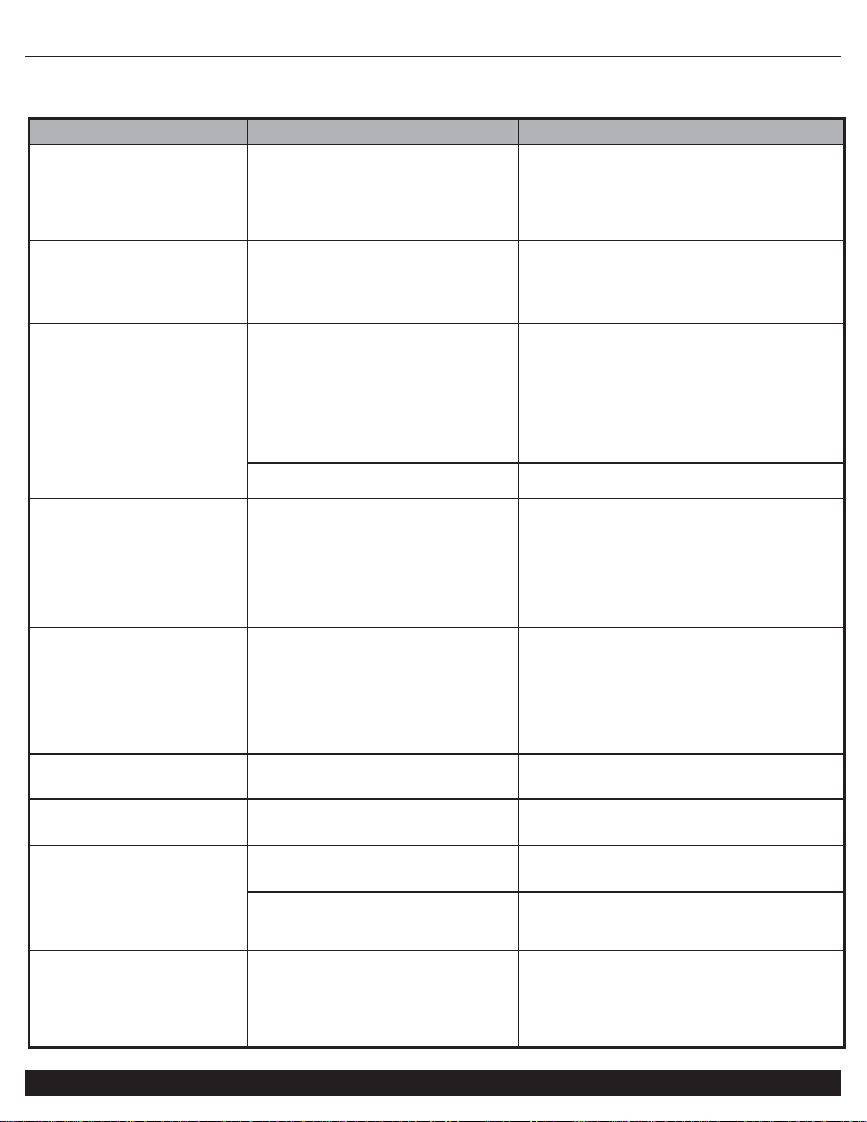
TROUBLESHOOTING
PROBLEM
POSSIBLE CAUSE
POSSIBLE SOLUTIONS
Pressure drop in the tank.
Air leaks at connections.
Let the compressor build pressure in the tank, to
the maximum pressure if possible. Brush soapy
water on air connections and look carefully for air
bubbles. Tighten leaky connections. If the
problem persists, contact Customer Support for
further assistance.
The unloader valve leaks when
the compressor is idle.
Unloader valve seal is defective.
Let the air in the air tank flow out until all the
pressure is released. Then remove the unloader
valve plug and clean the valve seal. If necessary,
replace the seal and then reinstall all
components. Replace Unloader.
The compressor stopped and
does not start.
The motor/pump thermal protector
turned on because the motor is
overheating.
Check that the main voltage corresponds to the
air compressor specifications. An extension cord
that is too thin or too long can cause a voltage
drop and cause the motor to overheat.
Excessive use (over 1 hour continuous use)
can cause the motor(s) to overheat
Allow the motors to cool down.
Motor windings are burned out.
Contact Customer Support.
The motor does not start and
makes a humming noise.
Head Pressure
——————————————————
Low voltage supply to the motors.
220 volts 60hz 1-phase required.
(acceptable range 215v – 250v)
Do a Check Valve Adjustment.
Drain air tank.
Remove check valve cap
Take out check valve spring Clean inside the
check valve and and elongate.the spring.
Replace spring and cap
The motor does not start or
starts slowly.
Low voltage supply to the motor.
Check that the main voltage corresponds to the
air compressor specifications.
An extension cord that is too thin or too long
can cause a voltage drop. Use heavy duty
extension cords.
Ensure that the air compressor is plugged into
a fully functional power outlet
The compressor is noisy with
metallic clangs.
Compressor motor/pump head gasket
or reed valve is damaged
Stop the compressor and contact Customer
Support. Service or replace motor/pump.
The compressor does not
reach the maximum pressure.
Compressor head gasket or reed valve
is faulty.
Stop the compressor and contact Customer
Support. Service or replace motor/pump.
The compressor doesn't seem to
provide as much air as it did
when new and/or the
compressor cuts off within a
much shorter time period.
The pressure switch needs adjusting.
Stop the compressor and contact Customer
Support.
The tank is full of water due to
condensation.
Open the drain valve and release the water from
the tank. Clean Auto Drain-Manual Drain Strainer
(filter).
The motor pump unit does
not stop when the tank
pressure reaches its
maximum working pressure
(120 PSI).(plus or minus 5
PSI)
SMART Controller (Pressure) Switch
defective or needs adjusting.
Stop the compressor immediately and contact
Customer Support.
Page 18
AIR COMPRESSOR
18
Customer Support: 1-866-409-4581
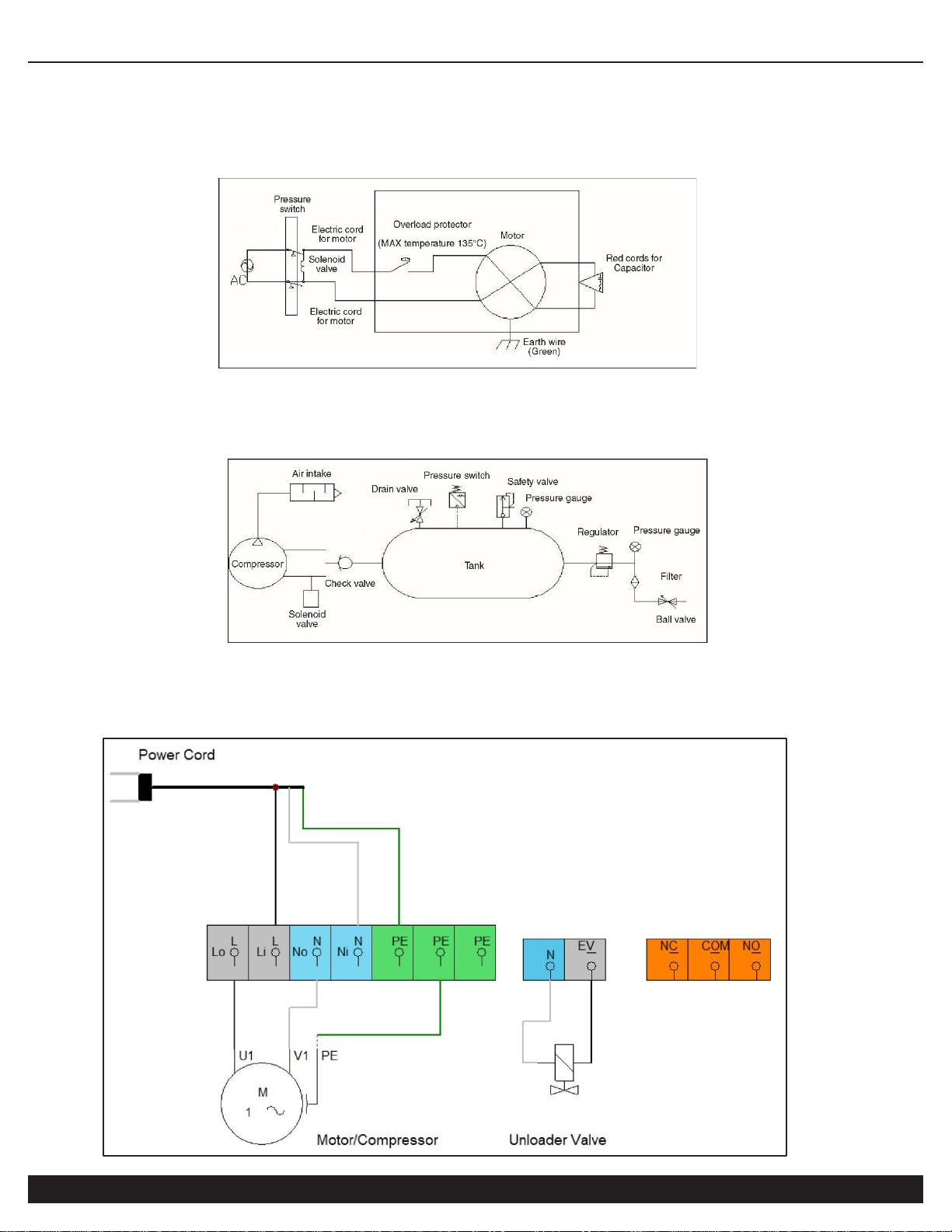
SPECIFICATIONS
Electrical Circuit
Air Passage Drawing
MDR2i Controller/Pressure Switch Wiring
Page 19

AIR COMPRESSOR
Customer Support: 1-866-409-4581
19
CALIFORNIA AIR TOOLS INC. LIMITED WARRANTY
This warranty is limited to Air Compressors distributed by:
California Air Tools, Inc.
8560 Siempre Viva Road
San Diego, CA 92154
Limited Warranty
California Air Tools Inc. will repair or replace, free of charge, to the original retail customer who purchased a California Air
Tools, Inc. Air Compressor from an authorized dealer, distributor or distributor’s dealer in North America.
This warranty does not transfer to subsequent owners.
California Air Tools Inc. will repair or replace, at its option, any parts of the portable air compressor that are proven by an
authorized service center to be defective in material or workmanship under normal use during the applicable warranty time period
as stated below. This limited warranty covers the cost of the replacement parts and labor for all defects when installed by an
authorized service center. Transportation charges are the responsibility of the customer. Any part replaced under warranty
becomes the property of California Air Tools Inc.
All parts replaced under warranty will be considered as part of original product, and any warranty on those parts will expire
coincident with the original product warranty.
Limited Warranty Periods
Non-commercial / Non-rental (personal use by a retail customer): 1 year parts and labor
Commercial / Rental (usage for income, business use): 1 year parts and labor
The limited warranty period begins on the date of retail purchase by the original purchaser.
Disclaimers, Limitations of Remedies & Exclusions
This warranty gives you specific legal rights, and you may also have other rights which may vary from state to state.
Disclaimer of Other Warranties
To the fullest extent permitted by applicable law, this limited warranty is exclusive and expressly in lieu of any and all other
warranties, including, without limitation, any implied warranties of merchantability or fitness for a particular purpose or any other
implied warranties that may arise from the course of dealing or usage of the trade. California Air Tools Inc. hereby declaims and
excludes all other warranties. To the extent that California Air Tools Inc. products are consumer products under applicable federal
and state law with respect to any customer, the duration of any implied warranties (including but not limited to implied warranties of
merchantability or fitness for a particular purpose) are limited to the shortest duration permitted by applicable law or the Limited
Warranty period provided herein, whichever is longer.
Limitations of Remedies
California Air Tools Inc. shall not be liable to customer, or anyone claiming under customer, for any other obligations or liabilities,
including but not limited to, obligations or liabilities airing out of breach of contract or warranty, negligence or other tort or any
theory of strict liability, with respect to the air compressor or California Air Tools Inc. acts or omissions or otherwise. To the fullest
extent permitted by applicable law, California Air Tools Inc. shall not in any event be liable for incidental, compensatory, punitive,
consequential, indirect, special or other damages, including but not limited to loss of use, loss of income, loss of time, loss of
sales, injury to personal property, or liability customer incurs with respect to any other person, or any other type or form of
consequential damage or economic loss.
Page 20

AIR COMPRESSOR
20
Customer Support: 1-866-409-4581
Exclusions
In addition to the foregoing disclaimers, limitations and terms, this limited warranty shall not apply to and does not cover
accessories, nor does it cover products that are in any way subject to any of the following:
1. Improper setup, installation or storage.
2. Lack of proper maintenance and service.
3. Accident, damage, abuse or misuse.
4. Abnormal operating conditions or applications.
5. Repair or modification by customer or any third party without written consent of California Air Tools Inc.
6. Use under operating conditions or in applications not recommended by California Air Tools Inc.
7. Normal wear.
8. The use of accessories or attachments not recommended by California Air Tools Inc.
9. Acts of God.
The application of these exclusions will be determined at the sole discretion of California Air Tools Inc.
Maintenance & Troubleshooting Guide
California Air Tools provides Maintenance & Troubleshooting Guide on our website WWW.CALIFORNIAAIRTOOLS.COM.
Valuable information regarding set-up, operation and maintenance.
Please visit our website and view these videos for beneficial information.
Service or Parts
Warranty is also available by keeping and showing your original receipt from the date of purchase to an
Authorized California Air Tools Service Center.
For all customer service inquiries call 1-866-409-4581 or visit
WWW.CALIFORNIAAIRTOOLS.COM
Go to the “Contact Us” Tab
Click on “Service & Parts” Buttons for the Fastest Service.
 Loading...