

Page 1
CAUTION
1.Since use of an antenna extremely influences efficiency of the wireless microphone
system, proper selection and set-up are necessary. The shorter the better is the
most important rule to keep distance between the microphone and the receiiving
antenna.
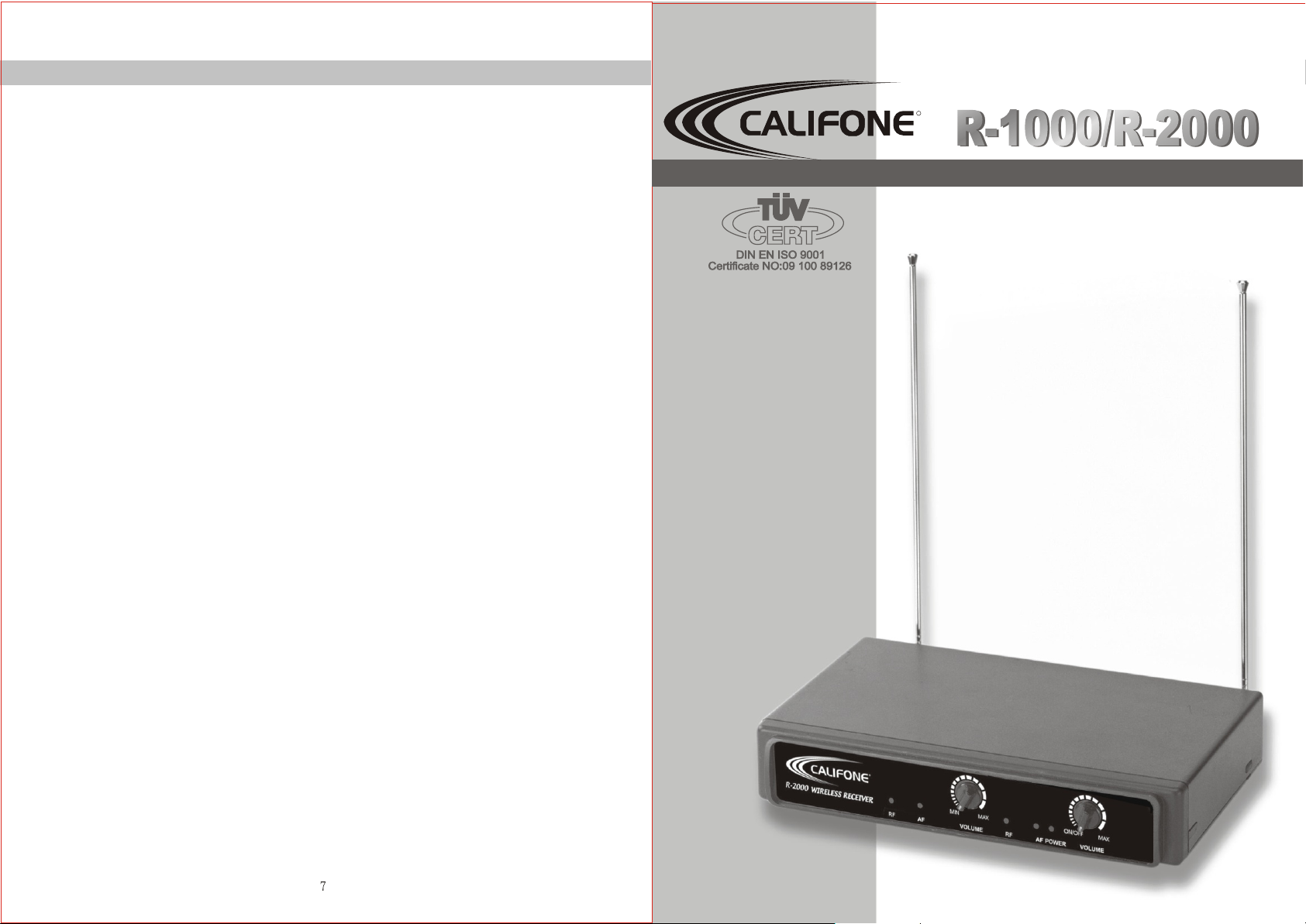
R
R-1000/R-2000R-1000/R-2000
R-1000/R-2000
WIRELESS MICROPHONE SYSTEM
2 In case of multi-channel operation, proper selection of non-interference channels is
of utmost importance.
3 Remove batteries out of the microphone if the unit is not to be used for a long period.
4 Tuned circuits and variable resistors & capacitors inside the transmitter and the
receiver have been precisely adjusted, please do not make any adjustment.
Otherwise, normal operation will be interrupted.
Operating Manual
Printed in Taiwan, SEP 2001
Page 2
GENERAL
OUTLINE
R-1000 / R-2000 is a VHF high-band non-diversity system with quartz controlled
fixedfrequency design. The receiver must be combined with Califone's Q- and Mseries of wireless microphone.
OPERATION OF THE OVERALL SYSTEM
1. Turn volume control of the receiver as well as the mixer or the equipment to be
used to the minimum then switch on the receiver. The pilot LED of the
receiver will light up and the AF signal indicator will give a flash.
COMPOSITION
1. MAIN FRAME:R-1000 / R-2000
2. ACCESSORIES:1)AC adapter 2)antenna X 1(R-1000) /antenna X 2(R-2000)
3)Output cable / PHONE 4)Operating manual
SYSTEM COMBINATION
1. MATCHING WIRELESS MICROPHONE:Q- and M- series such as Q-1000 &
M-1000
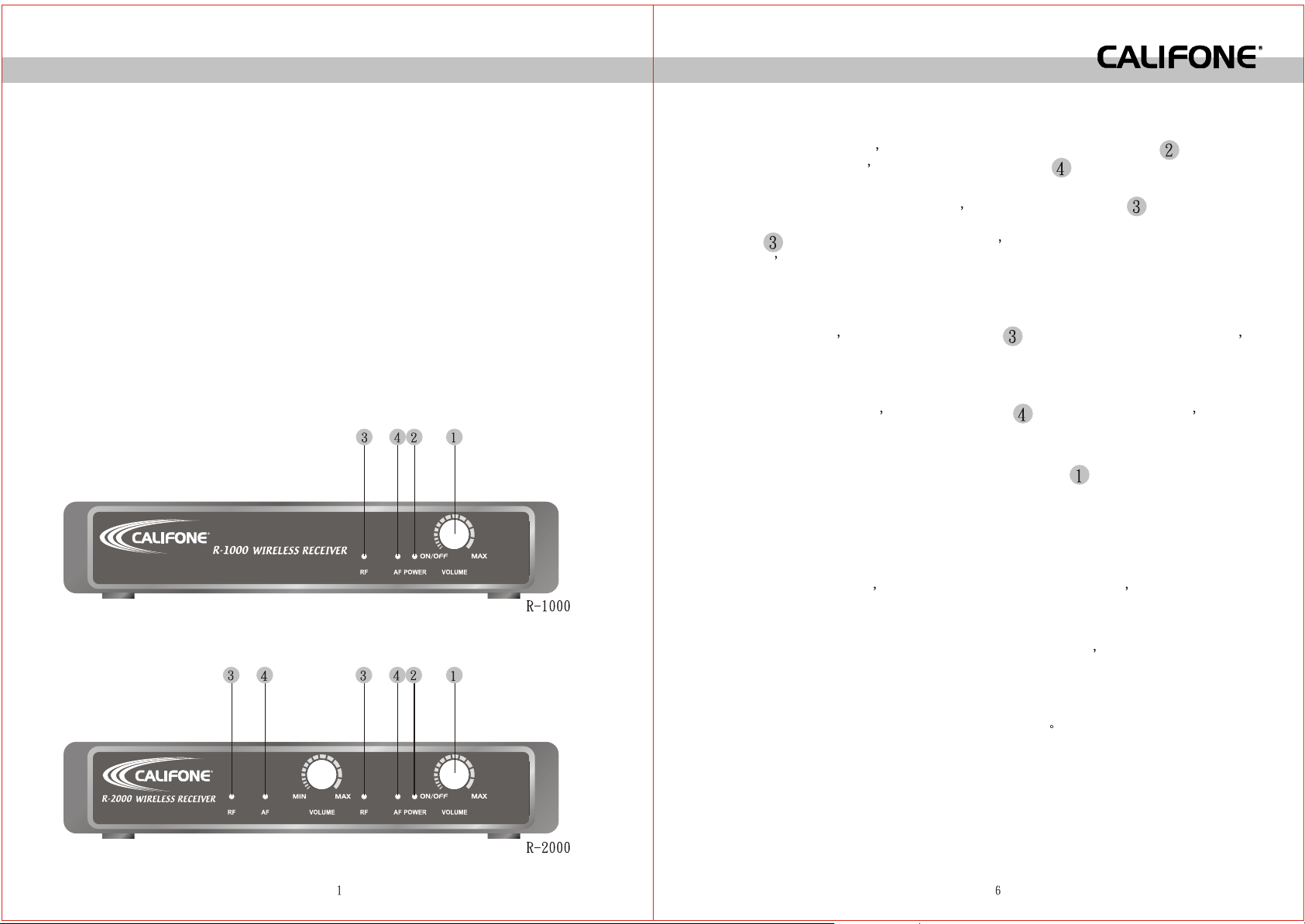
CONTROLS AND FUNCTIONS
FRONT PANEL
R
2. When a transmitter is switched on RF signal indicator LED of the receiver
will light up indicating that the system is in normal operation. When indicator
LED of the receiver does not light up indicating that the system does not
match both of the transmitter and the receiver should be checked whether they
are in normal operation or not.
3. When a matching transmitter is switched on at distance within 15 meters away
from a receiver RF signal indicator LED of the receiver does not light up
indicating that the system is matched but is in abnormal operation.
4. When sound is applied to the microphone while the system is switched on and
is in normal operation AF signal indicator will light up accordingly indica ting that audio output of the system is in normal operation.
5. AF output level can be adjusted by volume adjustor to match the maximum
input level of the equipment to be used.
6. Audio output level must be adjusted to match a proper input level of the mixer
or the equipment to be used. If output of the receiver is adjusted too high and
volume control of the mixer is turned too low, it will cause the mixer output to be
distorted. Conversely the mixer output will not be distorted but a poor S/N
ratio will be caused.
7. After proper adjusting the output volume of the system adjust volume control
of the mixer or the equipment to be used to get a desired sound level output of
the microphone.
8. Power supply voltage can vary from 12-15V DC
R
Page 3

OPERATION INSTRUCTIONS OF OVERALL SYSTEM
The overall system is a combination of a receiver and a wireless microphone. The
combination for R-1000 or R-2000 could be selected as the following.
BASIC COMBINATION SYSTEM
BASIC COMBINATION SYSTEM
R-1000 / R-2000 matches Q-1000 M-1000
USED AS MULTI-CHANNEL SYSTEM
When two or more wireless microphone are used carriers must be different from
the others in order to avoid mutual interference.
INSTALLATION OF THE SYSTEM
To make sure that the system performs correctly please place the receiver at
least 1 meter above the ground and at least 1 meter away from concrete walls or
metal surfaces to prevent any reflection. The microphone should also be at least 1
meter away from the receiving antenna as shown in Fig. 5.
REAR PANEL
CONTROLS AND FUNCTIONS
1.POWER SWITCH AND VOLUME CONTROL
Turn the knob clockwise until it clicks to switch on the power. Further turning will
increase the volume.
R
2.POWER ON INDICATOR
When power is switched on the power on LED will light up.
3.RF SIGNAL INDICATOR
Indicates RF signal received. As soon as signal is emitted from the microphone
the LED of the indicator will light up.
4.AF SIGNAL INDICATOR
Indicates the audio signal. When sound is applied to microphone LED will light
up.
5.ANTENNA INPUT JACK
For direct mounting of antenna or antenna extension cable.
6.UNBALANCED AUDIO OUTPUT JACK
7.DC POWER SUPPLY INPUT SOCKET
A 12-15V external DC power supply or an AC adapter could be connected to this
socket while the negative is grounded.
Page 4

INSTALLATION OF THE RECEIVER
USED AS A STAND ALONE SYSTEM
1.Install an antenna perpendicularly to the antenna input jack at the rear panel
of the receiver as shown in Fig. 1.
CONNECT
1.Connect the AF output of the receiver from unbalanced output jack to input
jack of the mixer by an output cable attached with "PHONE" plug as shown in
Fig. 2.
2.Connect a power adapter to the DC power supply input socket then plug the
adapter to an appropriate AC outlet with caution to the correct voltage under both
AC outlet and adapter marked. as shown in Fig. 3.
USED AS A PACK MOUNT SYSTEM
1.Mount the two connected R-1000 or R-2000 into an optional MP-60 panel as
shown in Fig. 4.
 Loading...