

Calibre UK PICA93LV User Manual

CALIBRE
PICA93LV
Parallel I2C Communications Adapter User Manual
Issue 1.3
22/07/1999
Calibre UK Limited
Cornwall House, Cornwall Terrace
Bradford, West Yorkshire, BD87JS, England
Tel No : (01274) 394125
FAX No: (01274) 730960)
E-mail:
Web-site
sales@calibreuk.com
www.calibreuk.com

CALIBRE
Welcome to the Calibre parallel I2C interface. This interface is designed to allow users to run
2
C Bus operations via PC parallel port.
I
2
If you have any queries relating to this or any other I
our web site www.calibreuk.com.
For technical support please e-mail techsupport@calibreuk.com or send your queries by fax to
(44) 1274 730960, for the attention of our I2C Technical Support Department.
COPYRIGHT
This document and the software described within it are copyrighted with all rights reserved. Under
copyright laws, neither the documentation nor the software may be copied, photocopied, reproduced,
translated, or reduced to electronic medium or machine readable form, in whole or in part, without
prior written consent of Calibre UK Ltd ("Calibre"). Failure to comply with this condition may result in
prosecution.
Calibre does not warrant that this software package will function properly in every hardware/software
environment. For example, the software may not work in combination with modified versions of the
operating system or with certain network adapter drivers.
Although Calibre has tested the software and reviewed the documentation, CALIBRE MAKES NO
WARRANTY OR REPRESENTATION, EITHER EXPRESS OR IMPLIED, WITH RESPECT TO THIS
SOFTWARE OR DOCUMENTATION, THEIR QUALITY, PERFORMANCE, MERCHANTABILITY, OR
FITNESS FOR A PARTICULAR PURPOSE. THIS SOFTWARE AND DOCUMENTATION ARE
LICENSED 'AS IS', AND YOU, THE LICENSEE, BY MAKING USE THEREOF, ARE ASSUMING THE
ENTIRE RISK AS TO THEIR QUALITY AND PERFORMANCE.
C product supplied by Calibre please visit
IN NO EVENT WILL CALIBRE BE LIABLE FOR DIRECT, INDIRECT, SPECIAL, INCIDENTAL, OR
CONSEQUENTIAL DAMAGES ARISING OUT OF THE USE OR INABILITY TO USE THE
SOFTWARE OR DOCUMENTATION, even if advised of the possibility of such damages. In
particular, and without prejudice to the generality of the foregoing, Calibre has no liability for any
programs or data stored or used with Calibre software, including costs of recovering such programs or
data.
Copyright Calibre UK Ltd
(c) 1999 Cornwall House, Cornwall Terrace
Bradford, BD8 7JS. UK.
E-mail: sales@calibreuk.com
Web site www.calibreuk.com
All World-wide Rights Reserved
Issue 1.3
All trade marks acknowledged
Calibre operates a policy of continued product improvement, therefore specifications are subject to
change without notice as products are updated or revised.
E&OE.
22/07/1999
Issue 1.3
22/07/1999

CALIBRE
Contents
INTRODUCTION 1
1.1. General Introduction 1
1.2. Packing List 1
1.3. . Configuring the Adapter 1
1.4. Bus Termination and Protection 1
1.5. Installing the Adapter 2
CONNECTING THE ADAPTER TO YOUR SYSTEM 3
2.1. Connector Pinout 3
2.2. Bus Capacitance Limitations 3
2.3. Power Supply 3
2.4. Resetting the Adapter 3
SOFTWARE UTILITIES 4
3.1. Introduction 4
3.2. DOS C Library/Programs 4
3.3. DOS QBASIC Library/Programs 5
3.4. Windows LIB/DLL Functions 6
USING THE UTILITIES 7
4.1. Introduction 7
4.2. C Routines 7
4.3. QBASIC Routines 14
4.4. Libraries for Programming in Microsoft Windows Environments 20
FURTHER INFORMATION 27
APPENDIX A Parallel I2C Communications Adapter Status Codes 28
APPENDIX B Parallel I2C Communications Adapter Control Codes 29
THE MOST COMMONLY ASKED I2C QUESTIONS 30
6.1. General Questions 30
6.2. DOS Software Questions 30
6.3. WINDOWS 95 and NT Questions 30
Issue 1.3 Page i
22/07/99

CALIBRE
INTRODUCTION
1.1. General Introduction
The Parallel I2C Communications Adapter is designed to connect to any IBM PC compatible parallel
port. It is based on the Philips PCF8584 bus controller, it features full I2C bi-directional compatibility as
either a master or slave. I2C connections are made via a 9 way "D" socket.
1.2. Packing List
Your Parallel I2C Communications Adapter is supplied with the following items:-
A. I2C CD - ROM
B. The PICA93LV unit (the actual adapter)
C. A cable set
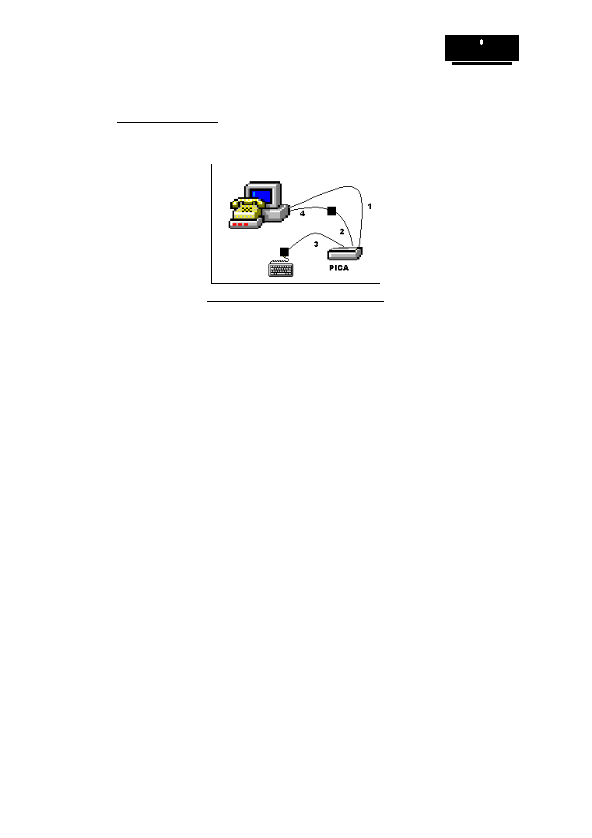
1 25 way parallel cable
2 6 pin mini DIN male -> 6 pin mini DIN male
3 5 pin DIN female -> 6 pin mini DIN male
4 6 pin mini DIN female -> 5 pin DIN male
.
1.3.
NOTE: MANY COMPONENTS ON THE ADAPTER CARD ARE STATIC SENSITIVE. OBSERVE
The adapter is supplied in a standard configuration which should suit most applications. However, the
bus termination and protection are link selectable. Read the following section to change the
configuration.
The standard configuration is bus termination and protection off
1.4. Bus Termination and Protection
Normally the system to which the Parallel I2C Communications Adapter is to be connected should
already have master pull up resistors fitted to the SCL and SDA lines. If this is not the case, LK6 and
LK7 can be used to connect 4.7K pull up resistors to the 5V supply on these lines.
The standard configuration is with these resistors disconnected.
The SCL and SDA lines are protected by 100R series resistors before exiting the adapter via the 9
way "D" socket. Upstream of the series resistors, the SCL and SDA pins on the PCF8584 are pulled
up with high value resistors (10K). These ensure that the I2C Bus is in a defined state even if no other
devices are connected.
LK4 and LK5 connect optional protection diodes to the SCL and SDA lines. When selected, these
lines are clamped to the 0V and + 5V lines giving protection against transients. If these diodes are
connected, the external I2C system will not function if the adapter is connected but not powered up.
The standard configuration is with these diodes disconnected.
Configuring the Adapter
NORMAL STATIC SENSITIVE PRECAUTIONS WHEN HANDLING THE CARD!
Issue 1.3
22/07/99
Page 1
CALIBRE
1.5. Installing the Adapter
Connect the PICA93LV to your PC as shown in figure 1 ( the cable numbers correspond to the
packing list above).
Figure 1.0 TYPICAL PC CONNECTION
Issue 1.3
22/07/99
Page 2

CONNECTING THE ADAPTER TO YOUR SYSTEM
2.1. Connector Pinout
All external connections are made via a 9 way "D" socket:
Pin Normal Mode
10V
20V
30V
40V
5NC
6 SDA (Bi-directional)
7+5V
8 SCL (Bi-directional)
9NC
CALIBRE
2.2. Bus Capacitance Limitations
The maximum allowable capacitance on the I2C bus in normal mode depends on the value of the SCL
and SDA master pull-ups, but never exceeds 400pF. Refer to Phillips Technical Handbook Book 4
Parts 12a and 12b for further details (see Further Information for references). Care should be taken in
choosing a length and type of interconnecting cable which will not exceed this limit.
2.3. Power Supply
Pin 7 on the "D" connector is connected to the PICA93LV power supply. This supply is fitted with
overload protection and up to 0.250mA can be drawn from here.
When shipped to you the bus voltage was factory pre-set to 3.3V for use with low voltage memories.
You can adjust the voltage by inserting a small screwdriver through the hole in the front panel.
Your PICA93LV has been factory set for use on 3.3V I2C bus systems. Use on 5V I2C bus
systems without adjusting the voltage WILL CAUSE PERMANENT DAMAGE to the PICA93LV.
The fault is factory detectable and you WILL BE CHARGED FOR THE REPAIR.
2.4. Resetting the Adapter
Each time the PICA93LV is re-configured via the Setup function it is automatically reset by software.
Issue 1.3
22/07/99
Page 3
CALIBRE
SOFTWARE UTILITIES
3.1. Introduction
Unpack the software from the CD-ROM in accordance with the instructions provided with the licence.
The Software utilities contain simple DOS routines in both C, QBASIC and Windows DLL / LIB (16bit
only) for use with Visual Basic and Microsoft C++.
These utilities can be used for setup the PICA and to perform basic communications.
3.2. DOS C Library/Programs
3.2.1. Files on disc
\C\CLIB\SPICA.LIB
\C\CLIB\CPICA.LIB
\C\CLIB\MPICA.LIB
\C\CLIB\LPICA.LIB
\C\LIBSOURC\PICA.C
\C\INC\PICA.H
\C\SOURCE\I2CINC.C
\C\SOURCE\PROMREAD.C
\C\SOURCE\PROMWRIT.C
\C\SOURCE\READ.MAK
\C\SOURCE\WRITE.MAK
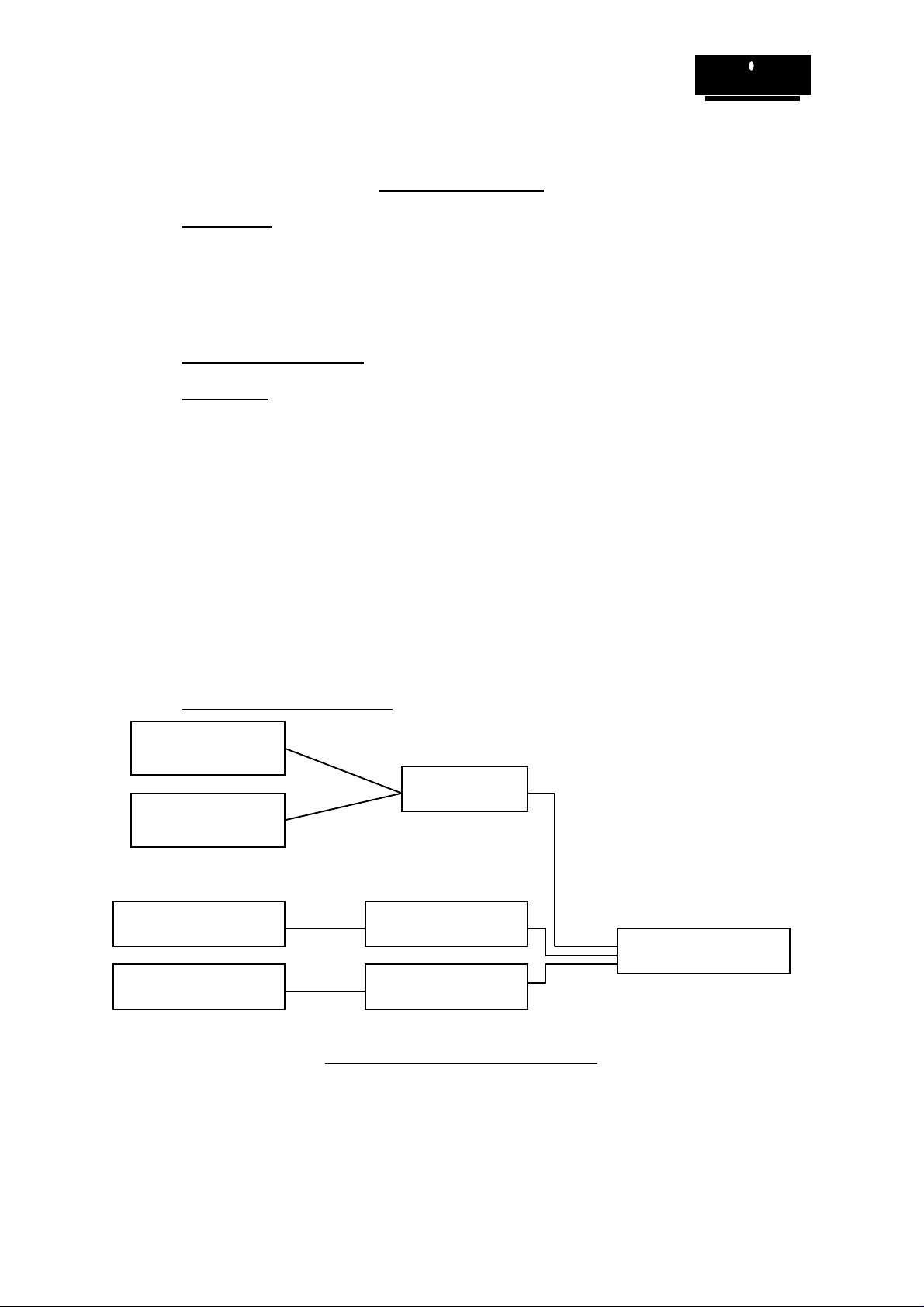
3.2.2. Typical C Project Arrangement
The library containing the low level functions (small memory
model)
The library containing the low level functions (compact memory
model)
The library containing the low level functions (medium memory
model)
The library containing the low level functions (large memory
model)
The source code for the libraries
The include file for the library
The I2C transfer functions
Sample EEPROM reading function
Sample EEPROM writing function
Make file for PROMREAD.C
Make file for PROMWRIT.C
#include DOS.H
PICA.H
MAKELIB
PICA.C
XPICA.LIB
#include PICA.H
I2CINC.C
Compile
I2CINC.OBJ
LINK
PROMREAD.EXE
User application
e.g. PROMREAD.C
Figure 2.0 shows a typical C project, Calibre UK Ltd have produced the library files, SPICA.LIB,
MPICA.LIB, CPICA.LIB and LPICA.LIB, which contains all the low level functions required to interface
to the adapter via the parallel port. These libraries cover the standard memory models, the library
appropriate to the memory model of your project will require linking with the object files.
Issue 1.3
22/07/99
Page 4
Compile
Figure 2.0 Typical Project Arrangement.
PROMREAD.OBJ

CALIBRE
The I2CINC.C file contains all the functions required to build an I2C transfer. This will require
compiling (note the include file) to produce an object file. Once the object files have been created link
them together with the library file to create your applications executable file.
The functions contained in I2CINC.C are as detailed below:Subroutine Name Brief Functional Description
setup Sets user defined initial conditions.
getstatus Reads status register.
sendaddress Sends slave address, data transmission mode and start signal.
sendstop Sends stop signal.
writebyte Writes a byte of data to a previously specified address.
readbyte Reads a byte of data from a previously specified address.
restart Sends Restart and slave address of device which is to be communicated
with, without sending a Stop.
Two sample programs are also supplied, these examples show how the functions provided in
I2CINC.C are put together to provide a complete I2C transfer. The sample programs are:-
PROMREAD.C Reads a number of bytes from an I2C serial EEPROM.
PROMWRIT.C Writes a number of bytes to an I2C serial EEPROM.
These programs were compiled using the Zortech C compiler the make files used are supplied. If you
are using the Zortech C compiler copy the desired make file to MAKEFILE then type MAKE<CR>.
Editing the make files will reveal that the file I2CINC.C is compiled and linked with the application.
The makefiles are:-
READ.MAK The make file for PROMREAD.C
WRITE.MAK The make file for PROMWRIT.C
If you are not using the Zortech C compiler you will have to create a similar make file - see your
compiler documentation for further information.
3.3. DOS QBASIC Library/Programs
3.3.1. Files on disc
\B\SOURCE\I2CINC.BAS
\B\SOURCE\PROMREAD.BAS
\B\SOURCE\PROMWRIT.BAS
The I2C functions contained in I2CINC.BAS are detailed below:Subroutine Name Brief Functional Description
setup Sets user defined initial conditions.
getstatus% Reads status register.
sendaddress% Sends slave address, data transmission mode and start signal.
sendstop% Sends stop signal.
writebyte% Writes a byte of data to a previously specified address.
readbyte% Reads a byte of data from a previously specified address.
restart% Sends restart and slave address of device which is to be communicated with,
without sending a Stop.
Two sample programs are also supplied, these examples show how the functions provided in
I2CINC.BAS are put together to provide a complete I2C transfer. The sample programs are:PROMREAD.BAS Reads a number of bytes from an I2C serial EEPROM.
PROMWRIT.BAS Writes a number of bytes to an I2C serial EEPROM.
The I2C transfer functions
Sample EEPROM reading function
Sample EEPROM writing function
Issue 1.3
22/07/99
Page 5

3.4. Windows LIB/DLL Functions
3.4.1. Files on disc
\readme.doc User Information
\win\c\I2cinc.h "C" function prototypes
\win\c\lpti2c.lib I2C "C" library
\win\vb30\lpti2c.bas Visual Basic 3.0 declarations
\win\vb30\lpti2c.dll I2C Visual Basic dynamic link library
The following functions are implemented in the windows libraries:void far _pascal _export setup (int baseaddress, int ownaddress, int sclk, int statuswait);
int far _pascal _export sendaddress (int slaveaddress, int setnack);
int far _pascal _export restart (int slaveaddress, int setnack);
int far _pascal _export getstatus (void);
int far _pascal _export writebyte (int wrData);
int far _pascal _export readbyte (int setnack);
int far _pascal _export sendstop (void);
int far _pascal _export recover (void);
int far _pascal _export sendbytes (int __far *transferarray);
int far _pascal _export getbytes (int __far *transferarray);
void far _pascal _export slavelastbyte (void);
CALIBRE
Issue 1.3
22/07/99
Page 6

CALIBRE
USING THE UTILITIES
4.1. Introduction
Each utility is documented in a standard format which lists its name, usage, function and effect on the
adapter is given. The adapter should be setup prior to any data transfer.
4.2. C Routines
4.2.1. I2C Setup / Initialisation Routine
Function definition: void setup(int ownaddress, int sclk)
Usage: setup(ownaddress, sclk);
Function: procedure to set up Parallel I2C Communications Adapter.
Parameters are: int ownaddress
The address to which the adapter is to respond in slave mode. This forms the
upper 7 bits of the 8 bit address, the lowest bit being the Read(1) or Write(0)
bit. This means that if own = 0x57, the card will respond to a Write to address
0xAE and a Read to address 0xAF. Be sure not to select an address which is
already in use by any other device in your I2C system.
int sclk
The SCL clock rate (bit rate for I2C serial bus).
Value of sclk Approximate SCL (KHz)
090
145
211
31.5
Value Returned: none.
I2C status on exit: I2C status on exit from routine the Parallel I2C Communications Adapter will
have the serial interface enabled, also data reception acknowledge will be
enabled. The status register will contain 0x81 (assuming that no other
masters exist on the I2C system, if this is not the case then the contents of
the status register will also depend on externally generated bus activity).
Example Usage: (see also sample programs)
main()
{
int ownaddress, sclk;
ownaddress = 0x57; /* Own slave address set to 0x57 (hex) */
sclk = 1; /* Serial clock rate set to 45KHz */
setup(ownaddress, sclk);
}
Issue 1.3
22/07/99
printf("Parallel I2C Communications Adapter initialised\n");
/* This will set up the Parallel I2C Communications Adapter with */
/*an I2C slave address of 0xAE and a SCL clock rate of approximately 45KHz */
Page 7

CALIBRE
4.2.2. I2C Status Checking Routine
Function definition: int getstatus(void)
Usage: i2cstatus = getstatus();
Function: function to read status register of the Parallel I2C Communications Adapter.
Parameters are: None
Value Returned: int i2cstatus
where i2cstatus is an integer from 0x00 to 0xFF which indicates the current
status of Parallel I2C Communications Adapter. See Appendix A for details of
the status values returned.
I2C status on exit: the status of the Parallel I2C Communications Adapter will not be affected by
using the getstatus function.
Example Usage: (see also sample programs)
main()
{
int i2cstatus;
i2ctatus = getstatus ();
printf("Parallel I2C Communications Adapter Status = %x\n", i2cstatus);
}
/*This will read the Parallel I2C Communications Adapter's current status*/
4.2.3. I2C Address and Start Sending Routine
Function definition: int sendaddress (int slaveaddress, int setnack)
Usage: i2cstatus = sendaddress(slaveaddress, setnack)
Function: This is the procedure to send Start and slave address of device which is to be
communicated with.
Parameters are: int slaveaddress
The 8 bit slave address of the device which is to be communicated with. This
will be an even number if the adapter is to write to the slave, add 1 to get an
odd number if the adapter is to read from the slave.
int setnack
This controls whether the Parallel I2C Communications Adapter transmits an
Acknowledge down the I2C Bus on reception of a byte. The last byte received
during a transfer must not be acknowledged. If setnack = 0 then acknowledge
is enabled, if setnack = 1 then acknowledge is disabled. Therefore, if a read
(odd numbered) address is being sent AND only 1 byte is to be read, setnack
should be set = 1; in all other cases it must be clear = 0.
Value Returned: int i2cstatus
The value returned depends on whether the Start and address were sent.
If the start and address have been sent then the status returned will either be
0x00 (bus busy data sent and acknowledged), or 0x08 (bus busy, data sent
but not acknowledged).
If the start or the address cannot be sent (either the bus remained busy or the
address did not get sent) then the last status read IORed with 0x8000 will be
returned.
Issue 1.3
22/07/99
Page 8
 Loading...