


11
Contents
1. Before Operation..........................................................................................2
1.1 Precautions...........................................................................................2
1.2 Battery Information of Remote Control.....................................................2
1.3 The Remote Control Description..............................................................3
1.4 Locations and Names of the Controls.......................................................4
1.5 Description of the Rear Cabinet....................... .......................................5
1.6 Unit Installation.....................................................................................6
2. Common Operation......................................................................................7
3. Radio Operation...........................................................................................8
4. USB and MMC/SD Operation........................................................................11
4.1 Load/unload USB or Memory Card...........................................................11
4.2 Setting during playing.............................................................................11
4.3 Pause Playback.....................................................................................11
4.4 Stop Playback .......................................................................................11
4.5 Select Chapter/Track with UP/DN Buttons................................................11
4.6 Select Chapter/Track with Number Buttons..............................................12
4.7 Playback with Speed..............................................................................12
4.8 ID3 Function..........................................................................................12
4.9 Playback Repeatedly..............................................................................12
4.10 Zoom image........................................................................................12
4.11 Photo playback....................................................................................13
5. Trouble Shooting.........................................................................................14
6. Specification..........................................................................................cover

1. Before Operation
1.1 Precautions
1. Read through this instruction manual before installation and use.
2. Clear the panel and case with soft dry cloth only, do not apply any
kind of thinner, alcohol or sprays.
3. The apparatus shall not be exposed to dripping or splashing .
1.2 Battery Information of the Remote Control
Replace Battery in the Remote Control:
22
+ side up
Fig.1
Fig.2
B
A
Fig.3
1.Before using the remote control for the first time, pull the insulating
sheet out of the remote control as the direction indicated by the
arrow.(see fig.1)
2.Press the movable block hold as the direction indicated by the A arrow
(See fig.2), then pull the battery holder out of the remote control as
the direction indicated by the B arrow(see fig.2).
3.Replace the old battery by a new battery with (+) polarity side upward.
(See fig.3).
4.Insert the battery holder to the original position in remote control.
(See fig.3).
Note about the Battery of the Remote Control:
Improper use of battery may cause overheating or explosion. so that
1.
Result in injury or fire .
2.Battery leakage may cause damage to the remote control(Battery
Life: 6 months with normal use in normal room temperature).
3.Do not short the battery.
4.Do not throw the battery into the fire.
5.To avoid the risk of accident, keep the battery out of reach of children.
33
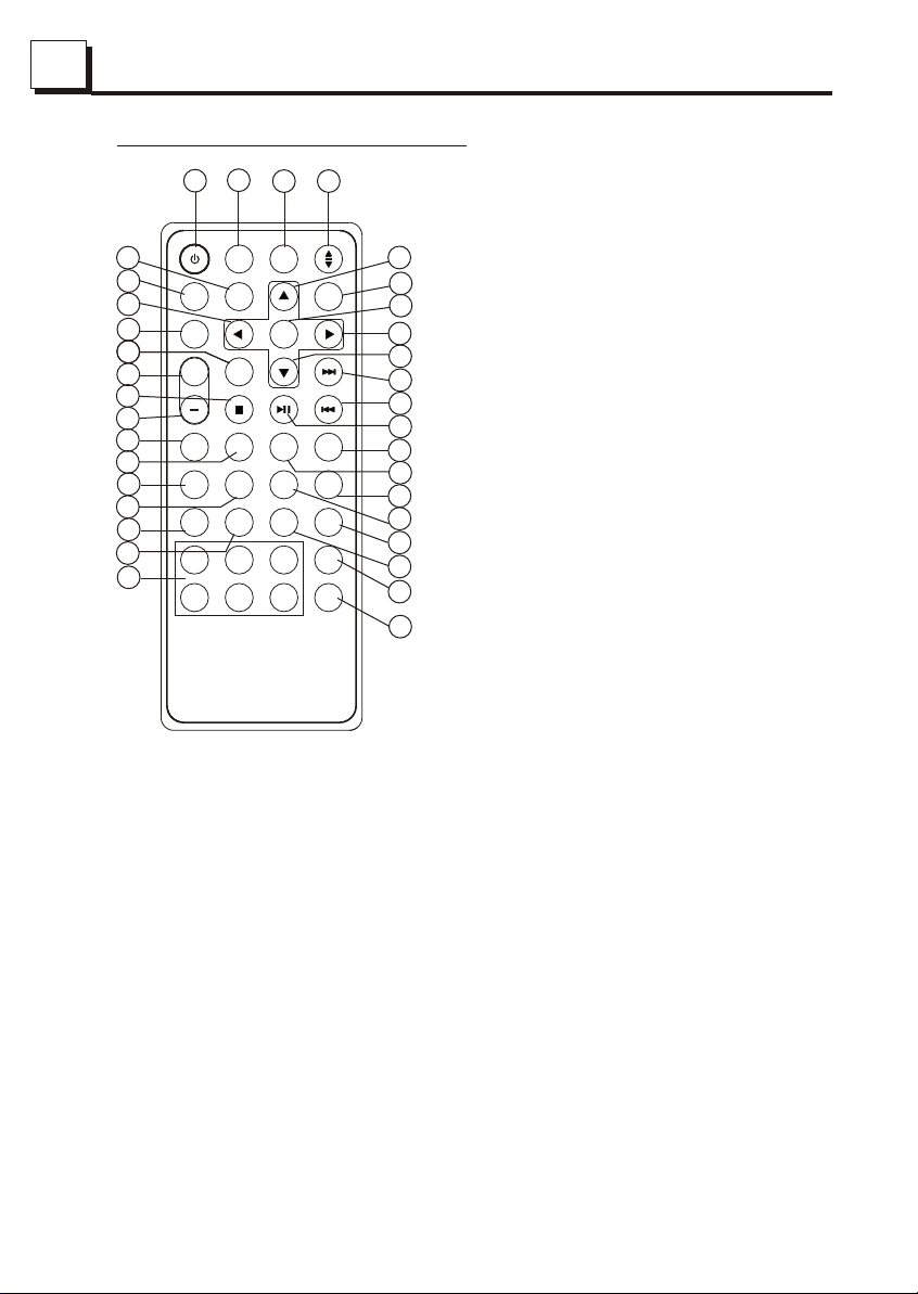
1.3 The Remote Control Description
3
30
1
26
13
PWR
29
23
MU
9
SEL
OPEN
BAND
0K
1212
TUP
SE
25
++
21
22
31
MOVI
MUSIC
34
28
27
19
15
11
E
TA
O
PHOT
CLK
1
4
FILE
AF
PTY
EQ
LOUD
LOC
MO/ST
AUDIO
RPT
3
2
6
5
15. LOC/RPT BUTTON
16. SUBTITLE BUTTON
MENUMODE
TEXT
ZOOM
SUB-T
4
2
1. TILT BUTTON
2. MENU BUTTON
24
6
8
5
7
10
32
EXIT
35
33
20
APS
18
17
14
16
3. POWER BUTTON
4. ^ BUTTON
5. >>| BUTTON
6. > BUTTON
7. |<< BUTTON
8. v BUTTON
9. SEL BUTTON
10. PLAY/PAUSE BUTTON
11. NUMBER(0~6) BUTTONS
12. SETUP BUTTON
13. MODE BUTTON
14. APS BUTTON
26. BAND BUTTON
27. AF/LOUD BUTTON
17. MO/ST & AUDIO BUTTON
18. ZOOM BUTTON
19. CLK BUTTON
20. PTY/EQ BUTTON
21. STOP BUTTON
22. VOLUME- BUTTON
23. < BUTTON
24. OK BUTTON
25. VOLUME+ BUTTON
28. TA/PHOTO BUTTON
29. MUTE BUTTON
30. OPEN BUTTON
31. MOVE BUTTON
32. TEXT BUTTON
33. EXIT BUTTON
34. MUSIC BUTTON
35. FILE BUTTON
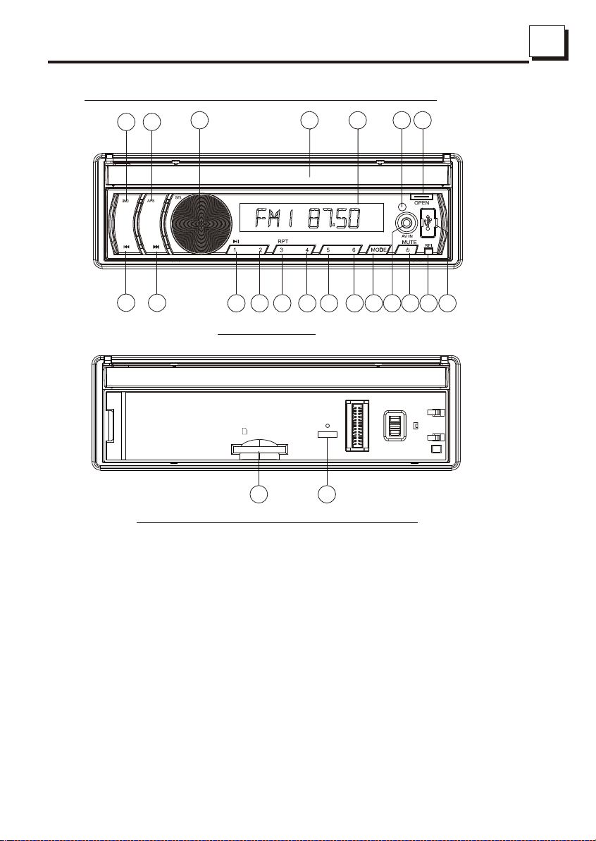
1.4 The Locations and Names of Controls on or in the unit
44
17 18
10
8
9
11 12
13
3 20
AF
15 16
The Front Panel
SD Card
6 19
RESET
The Front Facet after removing the front panel
121
2714
22
54
1. OPEN button
2. POWER/MUTE button
3. Monitor
4. AV IN socket
5. USB Jack
6. SD/MMC Card Slot
7. MODE button
8. VOL knob
9. >>| button
10. |<< button
11. PLAY/PAUSE/1 button
12. INT/2 button
13. RPT/3 button
14. RDM/4 button
15. - 10 / 5 button
16. + 10 / 6 button
17. BAND button
18. APS button
19. RESET button
20. Small LCD Screen
21. IR Remote Sensor
22. REL button
55
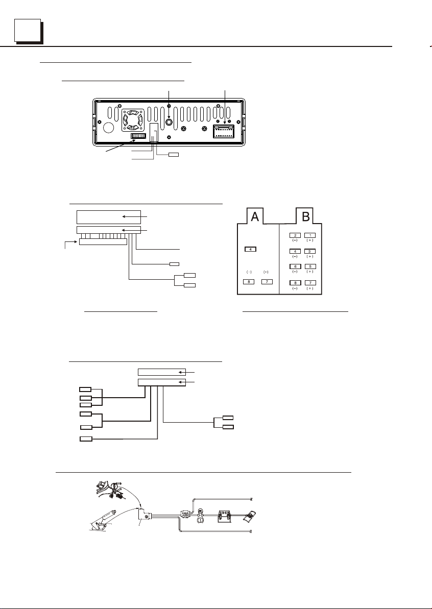
1.5 Wires Connection Description
The Description of the Wires Connection
Fixing Screw Bolt
GREEN
Wiring Connecting Socket 2
1. Parking wire must be connected. And the parking brake must be engaged in order for the monitor to work.
2. Use the clip end of the Ground Wire provided by manufacturer to connect Mounting Screw, using the other
end of the Ground Wire to connect the negative pole of the power source. Otherwise, the video on screen
maybe flashes.
PARKING LINE
WHITE
REVERSAL LINE
Black
Wiring Connecting Socket 1
Radio Antenna jack
The Description of the Wiring Diagram for Socket 1
WIRING HARNESS SOCKET
WIRING HARNESS PLUG
BLUE AUTO ANT
ISO FEMALE CONNECTOR
WOOFER LINE OUT
FRONT(BLACK)
RCA LINE OUT
GREEN
RED R
WHITE L
WIRING HARNESS
NOTES:
1. Only speakers with 4 ohms impedance may be used.
2. Ensure that the blue auto antenna cable does not make contact
with any ground connection.
The Description of the Wiring Diagram for Socket 2
WIRING CONNECTING SOCKET 2
RED R
WHITE L
YELLOW VIDEO
YELLOW
YELLOW
YELLOW
BROWN
AUDIO RCA AUX IN
GREY
VIDEO RCA OUT
BLACK
REAR VIEW CAMERA
WIRING CONNECTING PLUG 2
REAR(GRAY)
RCA LINE OUT
Black
CONNECTOR A
4. Yellow
7. Red
8. Black
CONNECTOR B
1. Violet
2. Violet/black
3. Grey
4. Grey/black
5. White
6. White/black
7. Green
8. Green/black
Memory(+)
Ground Ignition
Rear right speaker
Front right speaker
Front left speaker
Rear left speaker
ISO FEMALE CONNECTOR
RED R
WHITE L
Description of Connecting the Parking Brake Line to the Parking Brake System Built in the Car
Parking brake
Parking brake wire(Green)
Parking brake switch
(inside the car)
NOTE: after connecting the Parking Line, the video on the small monitor of the front panel will be display only after braking the car.
To metallic body or chassis of the car
 Loading...