

Page 1
Page 2
INSTALLATION
Tools for Installation
Use the 2 removal wrenches of the old unit to take out the old unit and place with this brand new car radio. The following tools and supplies may also be needed for the installation:
Tools for Installation: Philips Screw-drivers /Machine Screws /Wire Stripper /Wire Cutter /Hammer /Pencil /Electrical Tape /Electric Drill
Supplies for Installation: Machine Screws /Crimp Connectors /14 Gauge Wire for Power Connections /14-16 Gauge Speaker Wires
The above are not supplied.
Before you install
Automotive audio equipment installations can be challenging even to the most experienced of installation technicians. We strongly recommend that this unit should be professionally installed by a VAT registered installer (this is a requirement to validate the warranty).
IMPORTANT: Remove the two transport screws from the top fo the unit before installing.
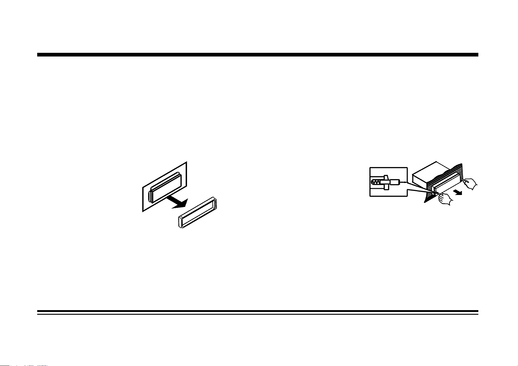
Remove the Old Unit from the Dashboard
1. Remove the outer trim frame.
DIN Front Mount
2. Insert the keys supplied with the
old unit into both sides of the unit
as shown in figure below until
they click. Pull to remove the old
unit from the dashboard.
DO NOT DISCONNECT WIRES
AT THIS TIME!
Mark Polarity of the Speaker Wires
Marking the polarity of the speaker wires will make it easier to connect the existing speakers to your car radio. Consult wiring diagram
of existing head unit before disconnecting any wires. If you are not positive of the polarity of the existing wires from the speakers to the
head unit, install new wires.
1. While the old unit is playing, disconnect the wires from one speaker.
2. Take a length of masking tape and fold it around the wire so it forms a flag.
3. On the masking tape mark the polarity of the speaker wires (+&-), as well as left or right, and front or rear.
4. Double check that you marked the first speaker correctly by checking that the speaker wires are the same at the head unit.
5. Repeat this procedure for all of the speakers.
6. Mark the power, ground, and any other wires also.
Page 3
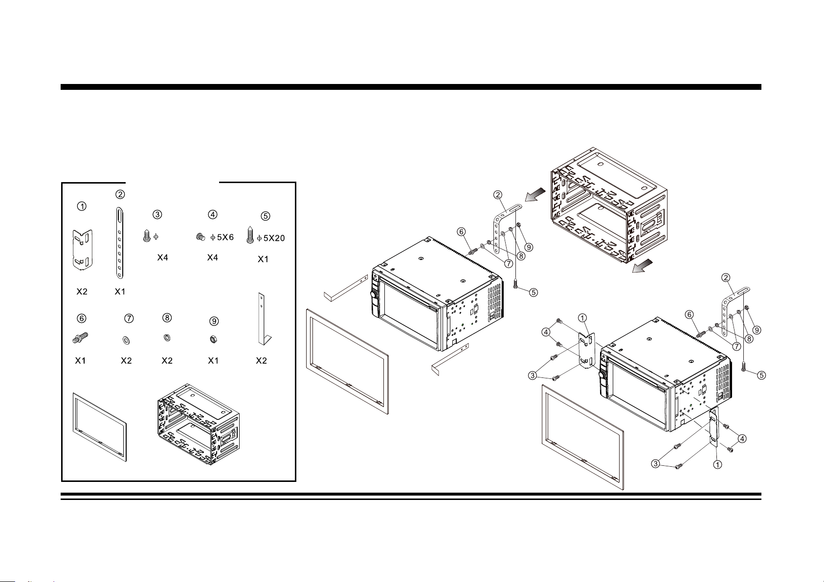
INSTALLATION
WARNING: Disconnect negative battery terminal from battery before starting installation. Consult the vehicle’s
owner’s manual for proper instructions.
NOTE: Mark the polarity of the existing speaker wires before disconnecting battery.
NOTE: Remove the two transport screws from the top of the unit before installing.
NOTE: Make sure there is enough space for the installation of this double-din unit.
SUPPLIED TOOLS
5X12
Page 4
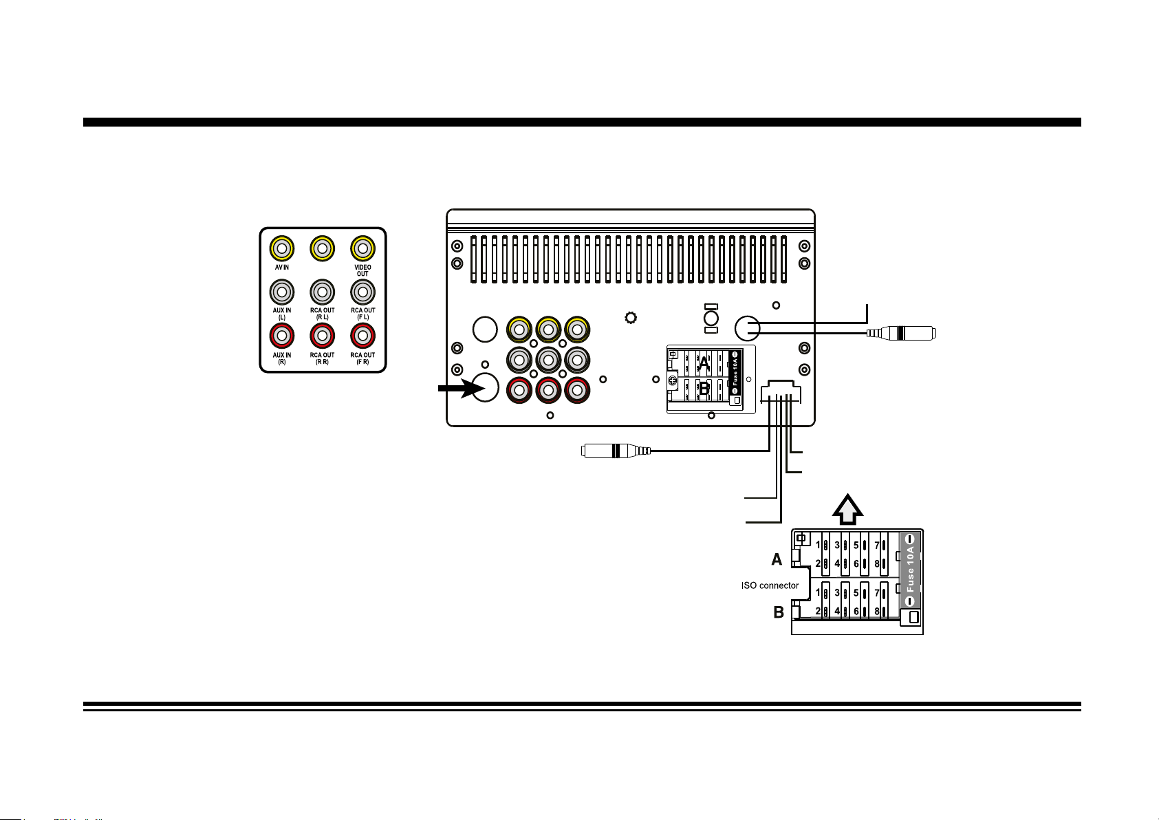
WIRING DIAGRAM
CAMERA
BACK
Radio Antenna
SWC (steering wheel control - 3.5mm jack)
Connector A
1. Rear right speaker(+)/Purple
Rear right speaker(-)/Purple-Black
2.
3. Front right speaker(+)/Grey
4. Front right speaker(-)/Grey-Black
5. Front left speaker(+)/White
6. Front left speaker(-)/White-Black
7. Rear left speaker(+)/Green
8. Rear left speaker(-)/Green-Black
Connector B
1. -
SUB 1 OUT (white)
SUB 2 OUT (red)
2. -
3. -
4. Battery 12V (+)/Yellow
5. Antenna power/Blue-White
-
6.
7. ACC+/Red
8. Ground/Black
Amplifier
power
(+12V output - blue/white)
External
Microphone
(black - 3,5mm Jack)
Reverse(purple-white)
Parking (green)
Page 5

WIRING DIAGRAM
General Wiring Notes:
Make sure You have a good chassis ground. Good ground connection will eliminate most electrical noise problems. A good chassis
ground requires a tight connection to the .vehicle’s metal chassis. The area around the ground connection should be clean, bare metal
without rust, paint, plastic, dust, or dirt for a good ground connection.
Black Ground
Connect to vehicle body/chassis. Make sure you have a good chassis ground. This will eliminate most electrical noise form the motor
and alternator. A good chassis ground requires a tight connection to ground. The area should be free from rust, paint or any form of dirt.
Red Ignition
Connect to car ignition switch for main power supply of the unit.
Yellow Memory Backup
Connect to electrical terminal always supplied with power regardless of ignition switch position.
Blue-White Remote
Connect to Auto-antenna or power amp control wire/remote connection. Maximum current 300mA 12VDC. (Low Current)
Green (Hand Brake - Ground)
Connect this wire to the hand brake wire of your car so that the display will be on only when the car is fully stopped.
Purple-White (Rear Gear - VCC)
Connect this wire to the rear gear wire of your car so that the backup camera function
can be activated when you car is in reverse gear.
Speaker Wiring Notes:
Follow the above wiring diagram to install the head unit with new or existing speakers.
1. This unit is designed for use with four (4) speakers with impedance between 4 Ohms to 8 Ohms.
2. An Impedance load of less than 4 Ohms could damage the unit.
3. Never bridge or combine the speaker wire outputs. When not using four speakers, use electrical tape to tape the ends of the unused
speaker outputs to prevent a short circuit.
4. Never ground the negative speaker terminals to chassis ground.
Page 6

Specifications
GENERAL
Operating Power.......................................................................................................................................12 Volts DC, Negative Ground
Output Wiring...............................................................................................................................Designed for using four speakers only
RCA line out.....................................................................................................................................................low-level outputs - 1000MV
Output Impedance................................................................................................................................Compatible 4 to 8 Ohm Speakers
Fuses.................................................................................................................................................................................................10 amp
Dimensions.......................................................................................................................................128mm(W) x 125mm(D) x 100mm (H)
Weight.....................................................................................................................................................................................................2.8 Kg
DVD/VIDEO/SYSTEM
Discs compatible.......................................................................DVD, VCD 1.0/1.1/2.0/3.0, MP3, CD, CD-R, CD-RW, PICTURE-CD
Video System..................................................................................................................................................................AUTO / PAL / NTSC
TFT/SYSTEM
Resolution.....................................................................................................................................................................800RGB(H) X 480(V)
Brightness/Contrast.................................................................................................................................................................400cd/m2/600
Viewing angle...........................................................................................................................................................................................70
Response Time...........................................................................................................................................................................Tr-2s/Tf-6s
Aspect Ratio..........................................................................................................................................................................................16:9
FM/TUNER
Tuning Range............................................................................................................ (USA) - 87.5 - 107.9MHz, (Europe) - 87.5 - 108 MHz
FM Sensitivity......................................................................................................................................................................................12dBu
Stereo Separation @ 1 Khz.................................................................................................................................................................35dB
AM/TUNER
Tuning Range............................................................................................................ (USA) - 530 - 1710 KHz, (Europe) - 522 - 1620 KHz
Am Sensitivity.....................................................................................................................................................................................30dBu
Page 7

BASIC OPERATION
1. Tuning the unit On / Off
Press the Power Button to turn the unit on. The opening screen of the unit will be showing on the TFT monitor. Press and hold the
POWER button again to turn the unit off.
2. Turning the TFT On / Off
During any play mode, press the Power Button once to turn the TFT screen off for screen saving and avoid distraction while driving.
The sound will continue to play. Press the Power Button again to turn the TFT screen back on.
3. Mode Selection
Press the MOD Button on the front panel to cycle the Play Mode between RADIO, DISC, USB, SD, AV in and TV. Play mode can be
chosen by touching on the Main User Interface also.
4. Sound Control
A. Volume
Use the VOL +/- Button to adjust the volume level. Turn the button clockwise to increase the volume, and vice versa. The larger the number of volume, the
higher the volume level. You can also adjust the volume by sliding the volume icon on top of the screen.
B. Bass
Press the SEL Button until the display shows “BAS”. Use the VOL +/- Button to adjust. When EQ is ON, bass control is not available.
C. Treble
Press SEL Button until the display shows “TRE”. Use the VOL +/- Button to adjust. When EQ is ON, treble control is not available.
D. Balance
Press SEL Button until the display shows “BAL”, then use the VOL +/- Button to adjust the balance between the left & right speakers.
E. Fader
Press SEL Button until the display shows “FAD”, then use the VOL +/- Button to adjust the balance between the front & rear speakers.
F. Other Audio Settings
You can adjust other audio settings like preset equalizer, loudness or subwoofer ON/OFF by tapping the “EQ” icon on the main menu, or on the control
menu of other audio/video play modes.
5. MENU Button
- In Radio and Aux modes, press the “MENU” button to go back to the home screen.
- In USB and SD modes, during music or video playback, press the “MENU” button once to go back to the directory page, in which you can choose the
desired file by pressing and turning the volume knob. Press again the “MENU” button to go back to the home screen.
6. Eject Button
Press the Eject Button on the front panel to eject DVD or CD disc.
Page 8

BASIC OPERATION
7. SETUP
Enter the setup menu in the home screen by tapping the “SETTING” icon on the main menu. Tap the items you would like to set. You can adjust audio,
date and time, language, cabibration, wallpaper,etc.
8. Day Light Saving
Tap the Day button on the OSD to increase brightness. Tap again to reduce brightness during night time. Tap again for black out the screen.
Page 9

Radio Operation
1. Choose Radio Band
Touch the AM button on screen to choose among the five radio bands - three FM Bands (FM1, FM2, and FM3) and two AM Bands (AM1,
and AM2). Each of the five bands can store up to six preset stations, for a total of 30 preset memory stations.
2. Radio Seek Function
In Radio Mode, touch and hold> or < Button to adjust the radio frequency automatically. Press the button once to adjust the radio frequency manually.
3. Save Your Preset Stations
There are six numbered preset buttons on the the screen (P1-P6) which can store and recall stations for each band. While listening to a
radio station you would like to save as a preset, touch and hold any key from P1-P6 until you hear a beep. The station will be saved in
the designated number.
4. Mute
Touch the mute button to mute the unit. Touch again to disable the mute.
5. Mono/Stereo Reception Control
In FM radio mode, touch the ST button to select stereo or mono reception.
6. Local/Distance Reception Control
In radio mode, touch the LOC button to select local or distance reception.
7. RDS Control (Optional)
AF, TA, PTY are the RDS functions. They are applicable to certain countries only. For countries when RDS is not available. The touch
sensitivity of the button will be disabled.
8. Returning to Main User Interface
Touch the ”BACK” button or “MENU” button to return to the main user interface.
Page 10

DVD/VCD/CD Operation
1. Selecting Tracks
Press the SEEK >>| Button to advance to the next track. Track numbers will be shown on the display. Press the SEEK >> to fast
forward.
Press the SEEK |<< Button to go to a previous track. Track numbers will be shown on the display. Press the SEEK << Button to
fast reverse. Press >|| button, disc will puase to play, Press it again disc will play again. On the Remote Control, use the |<< or >>|
Buttons.
2. Insert / Eject CD
Press the Eject button to open the disc window. Insert a disc into CD slot with label side up. The disc will be automatically loaded into
the unit. The unit will display the opening screen with loading status and the disc will play automatically. Press the EJECT Button to
eject the disc from the slot. If the disc is not removed from the slot within 10 seconds, it will automatically be loaded into the slot again.
When the disc is ejected and removed (or not removed), the unit will automatically switch to radio mode.
3. Audio Setup
Tap to enter audio setup which is also available in the SETTINGS LOGO in the OSD
4. Control of DVD/CD functions
The control of DVD/CD functions is by the touch menu onscreen or by remote control. The functions described below can be found in
either way. To access onscreen touch menu, touch the center of the screen and the menu will appear below. Touch the arrow button
on the right to toggle between the 3 pages of onscreen menu to adjust functions described below.
5. OSD (Display information)
Press the OSD button so that the OSD will display on the monitor. Details such as title, track, playtime, etc, will be shown.
6. DVD System Setup
Press the setup button to enter the DVD system setup. DVD system setup include password setting, rating level, region codes.
7. Navigation Key/Cursor (Up/Down/Left/Right) Buttons
a. Press MENU key title button to activate the DVD disc menu use on the screen, choose the desired item with cursor buttons.
Press “ENTER” button to confirm the selected and star playing.
b. In picture play mode, press cursor buttons to choose the image display mode.
Page 11

DVD/VCD/CD Operation (Con’d)
8. Track Search
Press the GOTO button to search the desired track to play the Disc. The OSD will be prompted. Make use of the navigation keys
and digit keys on the touch screen to choose your desired chapter, track. Press the ENTER button to confirm your selection.
9. Repeat Function
Press the Repeat button to toggle between repeat chapter, repeat title, repeat all and repeat off.
10. Menu Playing (for DVD only)
Tap so that the menu of the disc will be prompted
11. Audio Selection (for DVD only)
Press the AUDIO button on the remote control, in order to choose the audio language. The audio languages available differ from
Disc to Disc. You can also use the setup menu to confirm. Refer to the packing of the Disc for details.
12. Title Playing (for DVD only)
Press the TITLE button so that the first title track of the DVD will be played.
13. Subtitle Selection
Press the Sub-T button to choose the sub-title you want. The sub-title languages available differ from Disc to Disc. You can also
use the setup menu to confirm. Refer to the packing of the Disc for details.
14. Zoom +/-
Press the zoom + / zoom - button to amplification / narrow 2/3/4 times.
15. Multi-Angle View
Press the ANGLE button on the remote control to perform multi-angle playback. The number of angles change in sequential order.
Note: The number of angles is different according to the disc. The function only work for discs having scenes recorded at different
angles. When no different angle is recorded, the OSD will show “ 00 ”
16. Programme Mode
Press the PROG button on the remote control to set the program play. Use the Navigation and Digit keys to set the Chapter and
Track no. as your desired sequence. Press Enter to begin the program play. Press the PROG button and confirm a blank program
again to cancel this operation.
Page 12

DVD/VCD/CD Operation (Con’d)
17. Electronic Skip Protection
This unit is programmed with Electronic Shock Protection (ESP) so that the video will be protected against rough roads for 5
seconds.
18. Returning to Main User Interface
Press the “BACK” button or “MENU” button to return to the main user interface.
Mixed Disc / USB-SD Operation
While you are playing mixed disc, USB, or SD card which contains MP3, WMA, JPG or DIVX formats, the unit will directly play the
audio files. However, you can tap the “PREVOUS” button to go back to the initiate selection among MUSIC, MOVIE and PICTURES.
Tap the category you prefer and follow through the folder/file selection to play the specific file you would like to enjoy.
You can press the “FILE” button to choose the file to beplayed.
Page 13

Bluetooth Operation
PAIRING
At BT mode, search bluetooth device by the phone and “RDD802BT Caliber” will appear in your phone. Input “0000” as password
to establish connection.
DIAL PAD
Touch the dial pad to dial the number you would like to call. Touch the CALL (green) button to send the number.
CALL RECORD
Press the HISTORY button to enter the phone book page to view received, missed and dialed calls. More details in the next page.
A2DP
Press the MUSIC button to enter the A2DP page to control playing music of your cellphone. More details in the next page.
REJECT CALL
Press the REJECT (red) button to end the call or to reject an incoming call.
RETURN TO USER MANUAL
Touch the arrow key on the top right corner to return to the main user interface.
View Received Calls
Touch the RECEIVED CALLS button, the received calls will be displayed. There will be up/down arrows displayed for you to view
them one by one.
View Missed Calls
Touch the MISSED CALLS button, the missed calls will be displayed. There will be up/down arrows displayed for you to view them
one by one.
View Dialed Calls
Touch the DIALED CALLS button, the dialed calls will be displayed. There will be up/down arrows displayed
one by one.
Playing Music on your cellphone
After activating music player in the cellphone, touch on screen to play or pause the music. Touch and to select up or down
one song in your song list.
for you to view them
Page 14

Settings
General Setting
The general setting menu includes wallpaper, logo, Key Beep, radio region, RDS region, aspect ratio, warning, calibration.
Time Setting
You can select Date, Time, Time mode and Time zone by tapping > ”KCAB“ paT .nwod/pu rof sworra eht ro snoitpo eht no yltcerid
after the setting to take effect.
Language Setting
There are diferent languages to select.You can select the language you want for OSD, disc menu, disc audio and disc subtitle.
Page 15

INFRA RED REMOTE CONTROL
3
1
2
4
10
11
12
13
14
15
16
17
MOD
5
6
7
8
9
BAND
AMS
RPT
LOC
RDM
PBC
1 2
5
9 0
ENTER
ST
PROG
SEEK
OSD
6 7 8
TITLE
ANGLE
VOL
SELECT
VOL
3
10
MUTE
SUB-T
SETUP
SLOW
ZOOM
SEEK
A
GO TO
18
19
20
21
22
23
24
25
26
UDIO
4
27
28
29
30
1.Power on/off
2. Mode Select Key
3.Play / Pause Function
4.Mute Sound Function
5.Band Select
6/7/10/21.Cursor Button in Menu Mode
8.Confirm The Track/Chapter Selected
or Select Item In SETUP Menu
9. Stop Playback
11. Repeat Play Function
12.Program The Tracks To Be Played/Stereo Selection
13.Random Play Function
14/26. Track Up / Down or Fast Forward / Backward
15. PBC Play Mode
16. Statistical Disc Information Display Button
17. Number Select Key
18.Subtitle Language Switching Key
19. Show All Track's Title (DVD only)
20. Display SETUP Menu
22. Play DVD in Slow Advance
23. Watch The DVD Content From Different Angle
24. Zoom In and Zoom Out Function
25/29. Adjust Volume Level
27. Sound Select Button
28. Change The Audio Output Method
30. Track Time Serach
This unit comes with a full remote control system. The CR-2025 Lithium battery is an included item with the
remote control. TO PLACE THE BATTERY:
(1) Remove
the cover from
the back of the
remote control.
(2) Insert a
CR-2025
Lithium battery.
(3) Insert the
battery holder
into the back
of the remote
control.
Operating the remote control
Aim at the face panel of the CD Receiver, the maximum distance at which signals can be received is about 6M. Make sure that the
signal path is not obstructed. Do not drop or throw the remote control. Do not place the remote control in a location that is exposed to
direct sunlight or next to a heating unit or other heat source.
Page 16

 Loading...