

Page 1
INSTRUCTION MANUAL
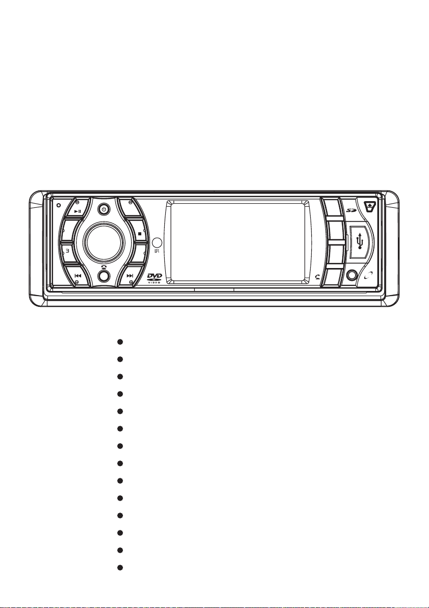
MCD 782
CAR MULTIMEDIA SYSTEM
DVD/MPEG4 PLAYER
MIC
2
INT
RPT
1 4
MODE
BND
RDM
5
6
GOTO
AS PS/
DVD/VCD/CD/CD-R/CD-RW/MP3/MPEG4 Compatible
Anti-Shock Mechanism
FM Stereo Radio
PLL Synthesizer Tuner
RDS (Radio Broadcast System) Function
Front Panel USB Input Port
SD/MMC Memory card slot
Built-in Bluetooth hands-free system
Front panel AV input
AV Output Socket
TA
ST
AF
REG
PTY
LOC
AV
IN
Sub-woofer Output Socket
3” Widescreen Digital TFT LCD Display
ISO Connectors for Power Supply and Speaker Outputs
4x75WHighPowerOutput
Page 2

CONTENTS
Safety Information.........................................01
Installation....................................................02
Using The Detachable Front Panel..............04
Wiring Diagram.............................................05
Operations....................................................06
Location and Function of Keys ...................... 06
Using The Remote Control.............................07
General Operations......................................08
Radio Operations.........................................09
RDS(Radio Data System) Operations.............10
AV Menu Settings.........................................11
Disc Operations...........................................12
Special Disc Operations................................15
Data Disc Play Operations ...........................17
USB Operations...........................................18
SD/MMC Memory Card Operations................18
AV IN Operations........................................18
Bluetooth Hands-free Function......................19
Setup............................................................21
System Setup.................................................21
Language Setup.............................................23
Audio Setup...................................................23
Digital Setup..................................................23
Attachment...................................................24
Trouble Shooting..........................................25
Specifications...............................................26
Page 3
Safety Information
CAUTION:
Mobile DVD player is a class 1 laser
product. However this mobile DVD player
uses a visible/invisible laser beam which
could cause hazardous radiation
exposure if directed. Be sure to operate
the mobile DVD player correctly as
instructed.
Use of controls or adjustments or
performance of procedures other than
those specified herein may result in
hazardous radiation exposure.
Do not open covers and do not repair
yourself. Refer servicing to qualified
personnel.
WARNING:
- To reduce the risk of fire or electric
shock, do not expose this equipment to
rain or moisture.
- To reduce the risk of fire or electric
shock, and annoying interference, use
only the recommended accessories.
- This device is intended for continuous
operation.
This product incorporates copyright
protection technology that is protected
by method claims of certain U.S. patents
and other intellectual property rights
owned by macro vision Corporation and
other rights owners. Use of this
copyright protection technology must be
authorized by Macro vision Corporation,
and is intended for home and other
limited viewing uses only unless
otherwise authorized by Macro vision
Corporation. Reverse engineering or
disassembly is prohibited.
Region Management Information
Region Management Information: This
Mobile DVD Player is designed and
manufactured to respond to the Region
Management Information that is
recorded on a DVD disc. If the Region
number described on the DVD disc does
not correspond to the Region number of
this Mobile DVD Player, this Mobile DVD
Player cannot play this disc.
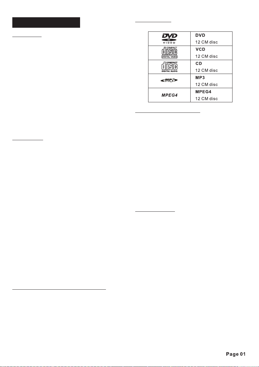
DISC NOTES
Disc formats supported by this player
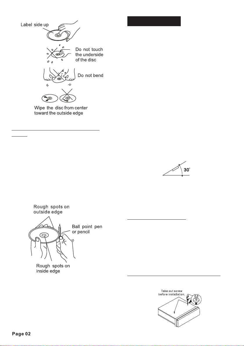
Handling and Cleaning
- Dirt, dust, scratches and warping discs
will cause disoperation.
- Do not place stickers or make scratches
on discs.
- Do not warp discs.
- A disc should always be kept in its case
when not in use to prevent from damage.
- Do not place discs in the following
places:
1. Direct sunlight.
2. Dirty, dusty and damp areas.
3.Near car heaters.
4.On the seats or dashboard.
Disc Cleaning
Use a dry soft cloth to wipe the surface.
If the disc is quite dirty, Use a soft cloth
slightly moistures with isopropyl
(rubbing) alcohol. Never use solvents
such as benzene, thinner or conventional
record cleaners as they may mar the
surface of the disc.
Note:
A disc may become somewhat
scratched (although not enough to make
it unusable) depending on the way it is
handled and conditions in the usage
environment. Note these scratches are
not an indication of any problem with the
player.
Page 4
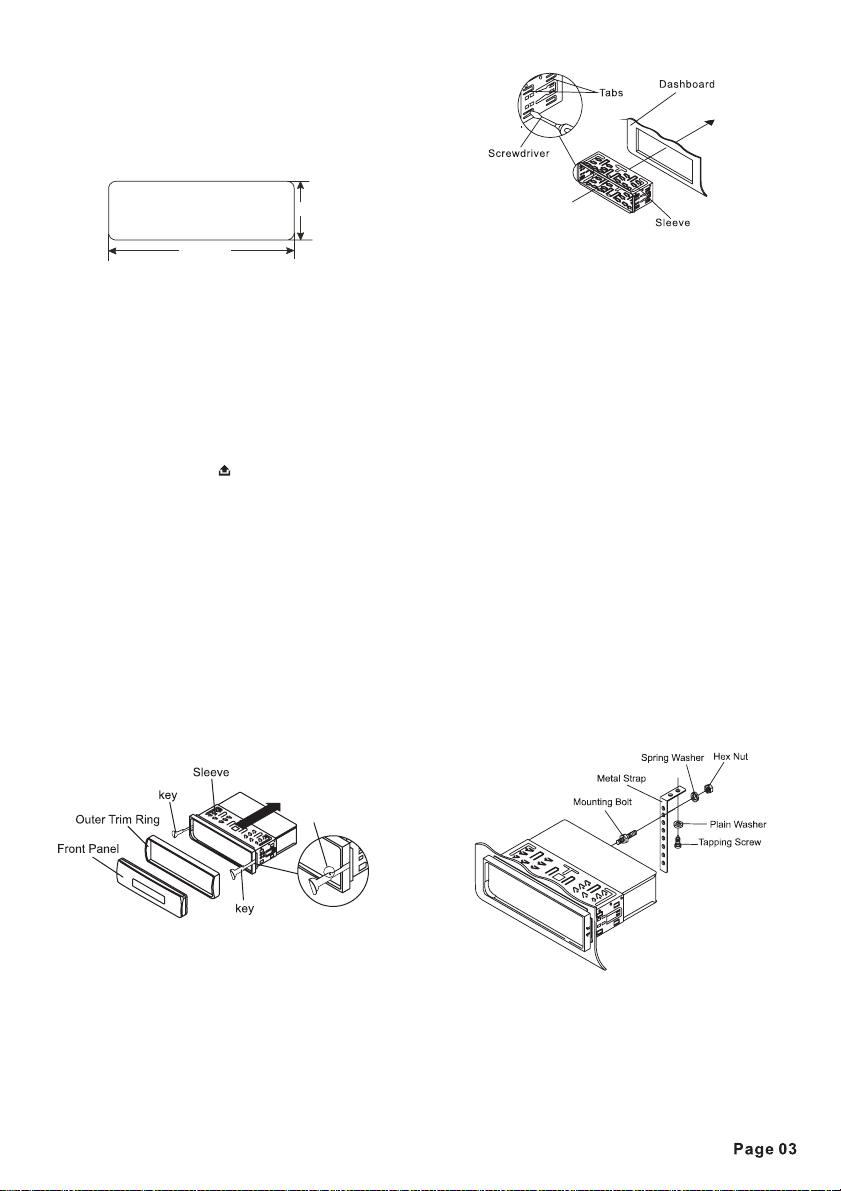
Preparing New Discs with Rough
Spots
A new disc may have rough edges on its
inside and outside edges. If a disc with
rough edges is used, the proper setting
will not be performed and the player will
not play the disc. Therefore, remove the
rough edges in advance by using a
ballpoint pen or pencil as shown on the
right. To remove the rough edges, press
the side of the pen or pencil against the
inside and outside edges of the disc.
Installation
Notes:
- Choose the mounting location where
the unit will not interfere with the normal
driving function of the driver.
- Before finally installing the unit, connect
the wiring temporarily and make sure it is
all connected up properly and the unit
and the system work properly.
- Use only the parts included with the unit
to ensure proper installation. The use of
unauthorized parts can cause
malfunctions.
- Consult with your nearest dealer if
installation requires the drilling of holes
or other modifications of the vehicle.
- Install the unit where it does not get in
the driver's way and cannot injure the
passenger if there is a sudden stop, like
an emergency stop.
- If installation ang e exceeds 30°from
horizontal, the unit might not give its
optimum performancel.
- Avoid installing the unit where it would
be subject to high temperature, such as
from direct sunlight, or from hot air, from
the heater, or where it would be subject to
dust, dirt or excessive vibration.
Din Front/Rear-Mount
This unit can be properly installed
either from 'Front' (conventional DIN
Front-mount) or 'Rear' (DIN Rear-mount
installation, utilizing threaded screw
Holes at the sides of the unit chassis).
For details, refer to the following
illustrated installation methods.
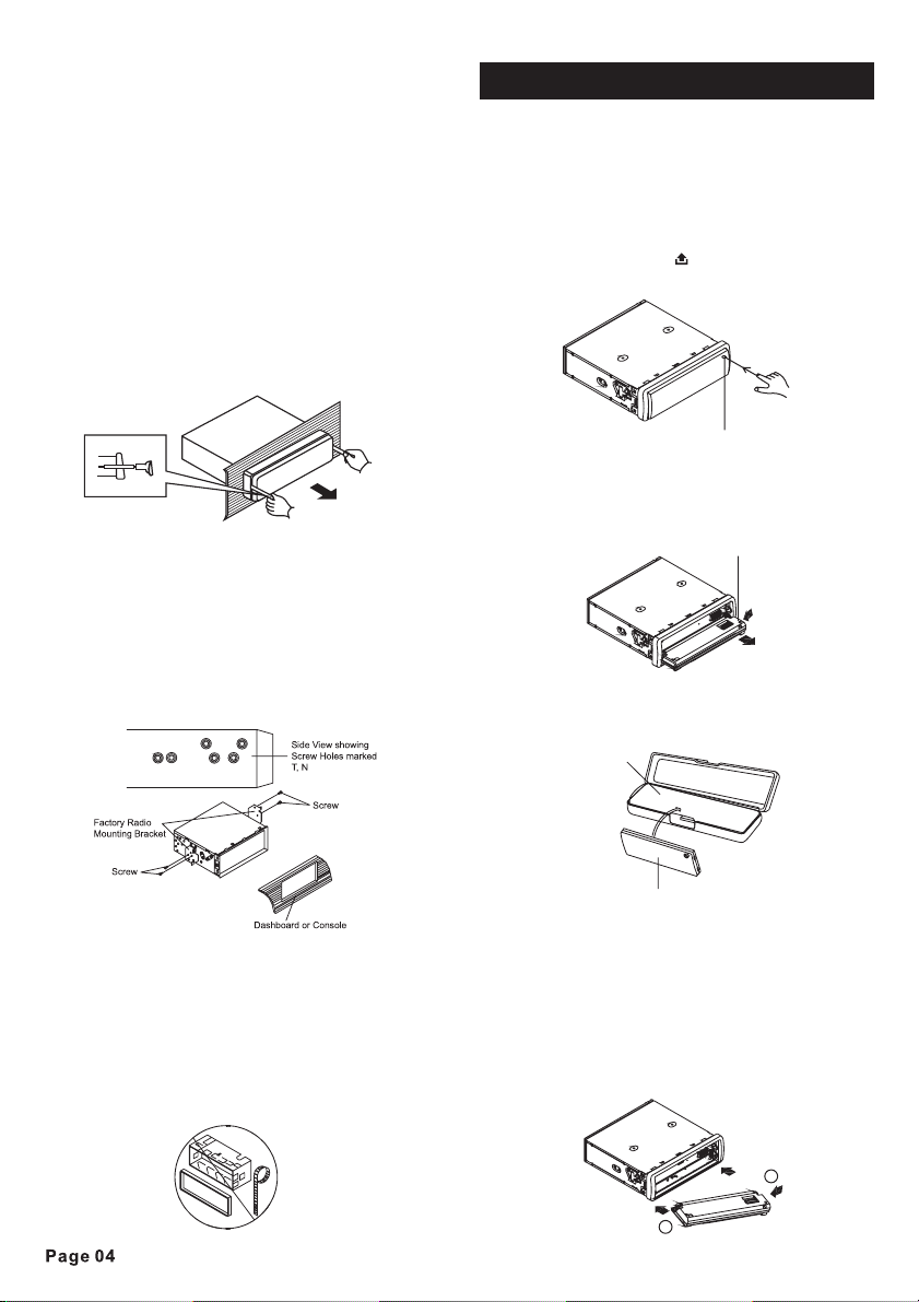
Take Out Screw Before Installation
Before install the unit, please remove
the two screws.
Page 5
1. DIN FRONT-MOUNT (Method A)
Installation Opening
This unit can be installed in any
dashboard having an opening as shown
below:
53 mm
182 mm
Installing the unit
Be sure you test all connections first,
and then follow these steps to install the
unit.
1. Make sure the ignition is turned off,
and then disconnect the cable from the
vehicle battery's negative (-) terminal.
2. Disconnect the wire harness and the
antenna.
3. Press the OPEN ( ) button to remove
the control panel (For details, refer to
'USING THE DETACHABLE FRONT
PANEL').
4. Lift the top of the outer trim ring then
pull it out to remove it.
5. Use the two supplied release keys to
remove the unit from the mounting
bracket. Insert the left (“L”) and right
(“R”) release keys as far as they will go
(with the notches facing up) into the
appropriate slots at the middle left and
right sides of the unit. Then slide the
sleeve off the back.
Notch
7. Reconnect the wire harness and the
antenna and be careful not to pinch any
wires or cables.
8. Slide the unit into the sleeve until it
locks into place.
9. To further secure the unit, use the
supplied metal strap to secure the back
of the unit in place. Use the supplied
hardware (Hex Nut (M5mm) and Spring
Washer) to attach one end of the strap to
the mounting bolt on the back of the unit.
If necessary, bend the metal strap to fit
your vehicle's mounting area. Then use
the supplied hardware (Tapping Screw
(5x25mm) and Plain Washer) to attach
the other end of metal strap to a solid
metal part of the vehicle under the
dashboard. This strap also helps ensure
proper electrical grounding of the unit.
Note to install the short threading
terminal of the mounting bolt to the back
of the unit and the other long threading
terminal to the dashboard.
6. Mount the sleeve by inserting the
sleeve into the opening of the dashboard
and bend open the tabs located around
the sleeve with a screwdriver. Not all tabs
will be able to make contact, so examine
which ones will be most effective.
Bending open the appropriate tabs
behind the dashboard to secure the
sleeve in place.
10. Reconnect the cable to the vehicle
battery's negative (-) terminal.
Then replace the outer trim ring and
install the unit's front panel.
Page 6
Removing the unit
1. Make sure the ignition is turned off,
and then disconnect the cable from the
vehicle battery's negative (-) terminal.
2. Remove the metal strap attached the
back of the unit (if attached).
3. Press the release button to remove the
front panel.
4. Lift the top of the outer trim ring then
pull it out to remove it.
5. Insert both of the supplied keys into
the slots at the middle left and right sides
of the unit then pull the unit out of the
dashboard.
2. DIN REAR-MOUNT (Method B)
If your vehicle is a Nissan, Toyota, follow
this mounting instruction. Use the screw
holes marked T (Toyota), N (Nissan)
located on both sides of the unit to fasten
the unit to the factory radio mounting
brackets supplied with your vehicle.
Using The Detachable Front Panel
REMOVING AND PROTECTING
DETACHABLE FRONT PANEL
The front panel of the unit may be removed
as a theft deterrent. After removing the
front panel, use the case provided to keep
the front panel from getting damaged.
.
1 Press the OPEN button to flip down
the front panel.
OPEN button
2 Grasp the right side of the front panel,
.
then gently push the front panel towards
the left side before pulling it out from the
unit.
3 Store the front panel in the protective
.
front panel
case provided for safe keeping.
protective case
Fasten the unit to the factory radio
mounting brackets. Align the screw holes
on the bracket with the screw holes on
the unit, and then tighten the screws
(5x5mm) on each side.
Note: the outer trim ring, sleeve and the
metal strap are not used for method B
installation.
front panel
TO ATTACH THE FRONT PANEL
Hold the right side of the front panel with the
plate facing down.
First attach the left side of the front panel to
the unit by inserting the hole into the left holder.
Then slightly push it leftwards and attach the
right side hole into the right holder.
Finally push up the front panel.
2
1
Page 7
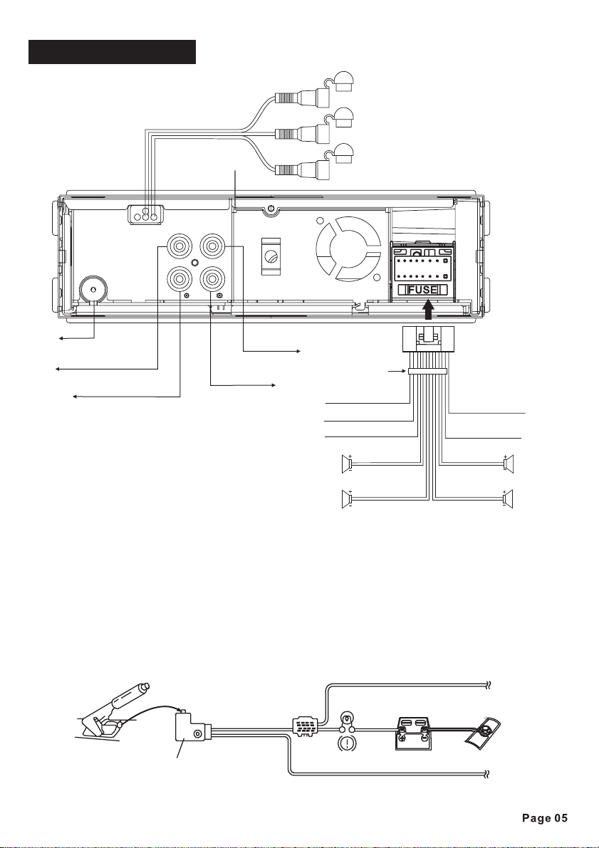
Wiring Diagram
White: RearLeft CH RCAoutput Socket
Red :Rear Right CHRCA output Socket
Green :Subwoofer output Socket
ISO CONNECTOR
YELLOW
BLACK
RED
WHITE /BLACK
LEFT
GREEN /BLACK
WHITE
GREEN
PINK/BLACK TO PARKING BRAKE B-
BLUE TO ANTENNA
GREY
GREY /BLACK
VIOLET
VIOLET /BLACK
FRONT
RIGHT
SPEAKER
REAR
Radio Antenna Socket
White: FrontLeft CH RCAoutput
Red :Front Right CHRCA output
Bluetooth Antenna
Yellow:Video Output Socket1
Yellow:Video Output Socket2
MEMORY B+
GROUND B-
ACC B+
FRONT
SPEAKER
REAR
Connecting the Parking brake wire to the vehicle’s parking brake system
The “PINK/BLACK PARKING BRAKE” wire must be connected to the parking brake system of your
vehicle. The unit will only play videos when the parking brake system is engaged, if the parking
brake system is not engaged, the TFT screen will display the message “
DRIVING
”. This is a safety feature designed to prevent the driver from watching a video while
driving. The video output of this unit is not affected by this.
DISABLED WHILE
Note:
In radio,disc playing mode, the images will be displayed on the screen whether or not the parking
brake system is engaged.
Parking Brakewire from carDVD player (Pink/Black)
Parking brake
indicator Light
Parking Brake
Parking Brakeswitch
(Activated byparking brake)
Car Battery
To metal body partor chassis ground of your car
Page 8
6
1
3
9
7
15
13
1 4
MIC
4
2
INT
14
5
RPT
17
21
MODE
BND
RDM
5
6
GOTO
8
18
10
22
25
24
TA
ST
AF
G
RE
16
20
PTY
LOC
AS PS/
19
1112
2
AV
IN
23
Page 9

Using The Remote Control
DISP
1
2
3
4
5
6
7
8
9
10
11
12
13
MUTE
A-B RPT
ZOOM
SETUP
BT MENU
TRK/TUN
TITLE
12
4
14
15
7
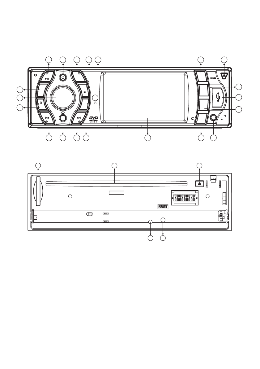
Descriptions of Function Controls
Power ( ) Button, MUTE Button
(1)
DISP(Display)
(2)
A-B Button
(3)
RPT (Repeat) Button
(4)
ZOOM(Zoom in/Zoom out) Button
(5)
Cursor Buttons ( )
(6)
ENTER Button
(7)
SETUP Button, BT MENU Button
(8)
Tune down, Seek down, track prevousButton
(9)
Tune up, Seek up, track next Button
(10)
TITLE( DVDTitle Menu) / PBC(Playback Control) Button
(11)
(Play/Pause) Button
(12)
Pre-set M1~M6 Button, Numeric 1~6 Button
(13)
TA(Traffic Announcement) Button, Numeric 7 Button
(14)
AF(List of Alternative Frequencies) Button,
(15)
REG(Regional Program)Button, Numeric 8 Button
MODE Button
(16)
AUDIO(Audio SetupSelect) Button
(17)
SUB-T(Subtitle Languageselect) Button
(18)
Button
(19)
,ANGLE( ) Button
(20)
Volume +/- Button
(21)
MENU Button
(22)
◄/►,▲/▼
Camera angleselection for somedisc
MODE
SUB-T
ANGLE
ENTER
MENU
DEL
5
AF/REGTA PTY
AUDIO
VOL
GOTO
PROG
3
RDM
6
98
0+
BAND
(23)
Fast ForwardButton, Button
(24)
Fast ReverseButton, # Button
(25)
GOTO Button
AS/PS (AutomaticSearch & Preset memory Scan) Button
(26)
(Stop) Button,DEL (Delete) Button
(27)
PROG(Programmed playmode) , LOC/DX Button
(28)
16
17
18
19
20
21
RDM (Random)Button, MO/ST Button
(29)
Numeric 0,+Button, BAND Button
(30)
PTY(Program Type) Button, Numeric 9 Button
Remark:
♦
Before you using the remote control,
please take the transparent insulator
slice off the bottom of remote control.
22
23
24
25
26
27
28
29
30
♦
Point the remote control at the remote
sensor within 2 meters.
♦
It may not be possible to operate the
remote control if the remote control
sensor is exposed to direct sunlight.
♦
Operation angle: about ±30°in each the
direction of the front of the remote
sensor.
- The remote control is a small,
lightweight precision device. To avoid
damage, short battery life, operational
errors and poor response, observe the
following.
- Do not subject the remote control to
excessive shock.
- Do not put in a trouser pocket.
- Keep away from food, moisture and
dirt.
- Do not place in direct sunshine.
Battery replacement
Battery type: a button cell lithium battery
(CR2025 3V)
1. Remove the battery holder by
pressing the locking tab with your thumb
and pulling it out.
B
A
Page 10

2. Replacing the battery
Replace the battery with the same type
and the (+) side facing up.
3. Closing the cover
Gently push in the holder until securely
locked into place.
General Operations
Reset the unit
Operating the unit for the first time, after
replacing the car battery or changing the
connections, you must reset the unit.
1.Turn off the unit power.
2.Press the ( ) button and
OPEN
remove the front panel, then press the
RESET
button with a ballpoint or similar
object to restore the unit to the original
factory settings.
Power on/off
In power off mode, switch on the unit by
pressing any button except the
button and the ( ) button or
EJECT
inserting a disc to disc slot USB device
OPEN
,
to USB port or SD/MMC card to card slot.
When the system is on, press and hold
the ( ) button long to turn off
POWER
the unit.
Adjusting the volume level
Rotate the knob on the head unit,
or use the or button on the
VOL+/-
VOL+ VOL-
remote control to adjust volume level.
Anti-theft LED Indicator
Designed as a theft deterrent, the red
LED will flash when the unit is turned off
and the front panel is removed.
ESP function
This car DVD player has the electronic
shockproof feature. So that if the unit
skips due to rough road conditions, the
music or video will be uninterrupted.
Mute on/off
When the unit is switched on, press the
button to turn off the sound
MUTE
instantly. Press the again to return
MUTE
it to the prior sound level.
To select playback mode
In power on mode, press button
MODE
repeatedly to select the different modes
in the following sequence: DISC(with a
disc inside the disc slot), USB(with USB
device inserted),SD/MMC(with SD/MMC
card inserted), BT, AV IN, TUNER mode.
Page 11

Last position memory feature
- During disc, USB, SD/MMC card
playback, press and hold the
POWER
button to turn off the unit, when you next
switch on it, the unit will resume playing
from the point that it was interrupted.
-During disc, USB, SD/MMC card
playback, press the button to
MODE
switch to a different mode, when you next
return to the previous disc, USB,
SD/MMC card playback mode again, the
unit will resume playing from the point
that it was interrupted.
Radio Operations
To select the radio mode
Press the button to select the
MODE
radio mode. You will see the following
radio screen on the
Stereo/mono
RADIO
STEREO LOC
Radio band
Frequency
Volume Clock
FM1
107.15
VOL 25
TFT screen.
Local/distant
MHZ 2
07 12:
Preset station
number
To select a radio band
In radio mode, Press the button
repeatedly to select
BAND
one of the three
radio broadcasting bands: ->FM 1-> FM 2
-> FM 3 ->.
Auto/ Manual tuning
- Automatic search mode:
Press the or button, the automatic
search will start. It will search upward or
downward for the strong signal radio
station within the current band.
Press and hold the or button until
“MANU” appears on the TFT screen, it
will change into manual searching mode.
- Manual search mode:
Press the or button repeatedly to
manually search upward or downward
step by step for the desired radio station
within the current band. For fast manual
searching, press and hold the or
button.
In manual search process, if the both
buttons haven’t been pressed within 5
seconds, it will change into automatic
search mode automatically. “MANU”
disappears on the TFT screen.
Stereo/Mono
FM station is received in stereo mode.
However, if the signal weak or reception
is not as good as you would like,
switching to MONO mode usually
improves the overall sound quality
Press and hold the button on the
head unit or briefly press on the
TA/ST
MO/ST
remote control to choose FM STEREO or
MONO audio effect.
Local/Distant
In urban settings, most stations are
strong enough and it should be set in
LOCAL mode.
Switch to DX (distant) mode to search for
stations with weaker signals.
Press and hold the button on
PTY/LOC
the head unit or briefly press the LO/DX
button on the remote control to choose
local reception or DX(distant) reception
mode.
To store / recall a preset radio stations
You can store up to a total of 18 radio
stations in the memory (18 FM), manually
or automatically.
- To store a station:
- Select a band (if needed)
- Select a station by or button,
refer to auto / manual tuning.
-HoldaPre-setbutton( - )forat
M1 M6
least 2 seconds.
- To recall a station:
- Select a band (if needed).
- Press a preset button ( - ) briefly
M1 M6
to recall the stored station.
Page 12

Auto store / Preset scan
- Preset scan:
Press the button to scan each
AS/PS
preset station. It will play a station for a
few seconds, then go to next station until
all 6 stations are scanned, finally the
radio will play at the preset station where
scanning started. The preset station
number on the LCD will flash during the
process. When you hear a station that
you wish to listen to, press the
AS/PS
again to stop the preset scanning.
- Auto store:
Press and hold the button for
AS/PS
more than 2 seconds to start auto store.
The radio will scan from the lowest
frequency, and automatically store the 6
strongest stations into the preset
memories. When auto store is complete,
the radio will start preset scan to the
stored 6 station
.
RDS (Radio Data System) Operations
Setting RDS mode
Briefly press the button to turn
AF/REG
the RDS mode on/off.
Whenever RDS is on, symbol “ ”
AF
appears on the TFT screen.
Program name is displayed when
receiving an RDS station.
“ ” starts blinking if the broadcasting
AF
signals getting worse. “ ” will be
ALARM
displayed when an emergency
broadcasting is received, meanwhile
sound output level will be automatcially
adjusted to the preset output level when
the volume level is set at minimum.
AF( alternative frequency) function
Press button short to switchAF
AF/REG
mode on or off. There are 3 state of the
segment
Segment “AF” off:
AF on the LCD display:
“”
AF switching mode
off.
Segment “AF” on:
AF switching mode
on, and has RDS information.
Segment “AF” flashing:
AF switching
mode is on, but RDS information is not
received yet.
When AF switching mode is selected, the
radio checks the signal strength of theAF
all the time. The interval of checking time
of each AFs depends on the signal
strength of current station, from a few
minute for strong station to few seconds
for weak station. Every time that newAF
is stronger than current station, it
switches over to that frequency for very
short time. Because the mute time ofAF
switching or checking time is very short,
it is almost inaudible in case of normal
program. During FM mode, when AF is
on, manual store, Auto store/preset scan
function can only receive and save RDS
program.
REG(Regional Program) function
Press and hold the button for 2
AF/REG
seconds to switch on or off region mode.
Some broadcasting stations change their
program from normal broadcasting to
regional broadcasting for a certain time
period.
When region is on, the current listening
program remains unchanged. When
region is off, it allows the reception
moved to the regional station.
TA(Traffic Announcement) Function
Briefly press the button to turn
TA TA
search mode on or off.
When search mode is on and a traffic
TA
announcement is transmitted:
- Switch to the traffic announcement
mode from any audio mode including
DVD(CD/MPEG4/MP3), USB/SD/MMC or
AV IN.
- Switch on the traffic announcement
automatically when the receiver is in a
waiting reception mode and the audio
signal is muted.
- When the traffic announcement is
over, the initial operation mode will be
restored.
- If the volume level was under the
threshold point it will be raised to the
,
threshold point.
- When mode is on, segment is
TA “TA”
turned on.
- When a TP station is
received,segment “TP” is turned on.
Page 13

TA interruption function
The current traffic announcement is
cancelled by pressing the button. But
the mode will not be off.
TA
TA
To select program type
Briefly press the button to enter or
PTY
exit the program type list. After turing on
the PTY list, the display as follows:
Radio band
Frequency
Stereo/mono
RADIO
FM1
PTY
100.7
HGTES234 ALARM
VOL 25
Local/distant
STEREO LOC
MHZ
Current PTY
information
TA AF RE G
ALARM
NEWS
AFFAIRS
07 12:
PTY list
Press the / button on the head unit
or ▲/▼ button on the remote control, you
can select different program types as
follows:
NEWS -> AFFAIRS -> INFO -> SPORT
-> EDUCATE -> DRAMA-> CULTURE ->
SCIENCE -> VARIED -> POP M ->
ROCKM->EASYM->LIGHTM->
CLASSICS -> OTHER M -> WEATHER ->
FINANCE -> CHILDREN -> SOCIAL ->
RELIGION -> PHONE IN -> TRAVEL ->
LEISURE -> JAZZ -> COUNTRY M ->
NATIONM->OLDIES->FOLKM->
DOCUMENT -> TEST -> ALARM ->
NEWS
After a few seconds,the unit will search
your selected program type
automatically. The PTY search stops
when the unit finds a station with
selected program type, otherwise,
the
the
PTY search automatically exits to normal
mode
. During the PTY search process,
press any key to stop the PTY search.
AV menu settings
AV Menu Overwiew
You can adjust various settings of the unit
from the AV menu.
The AV menu contains the menu items
and submenus shown in the figure below:
1. Press the knob on the head
unit, or the button on the remote
VOL+/-
MENU
control to activate AV menu.
2. Press the or button on the head
unit, or ▲/▼/◄/► button on the remote
control to select a menu item (AUDIO,
PICTURE, SETUP).
3. Press the knob on the head
unit, or the button on the remote
VOL+/-
ENTER
control to access your selected menu
item.
4. Rotate the knob on the head
unit, or press the or button on
VOL+/-
VOL+ VOL-
the remote control to adjust the item you
have selected.
5. Repeat steps 2 ,3 and 4 to adjust other
items if necessary.
6. Press the button on the head
unit or button on the remote
MODE
ZOOM
control to return to the previous menu.
7. Press the button on the remote
MENU
control to finish the procedure.
MENU
AUDIO
PICTURE
SETUP
VOLUME
BASS
TREBLE
BALANCE
AUDIO
00
FADER
00
EQ
00
LOUD
L.R
SUB.W
PICTURE
R.F
32
BRIGHT
CONTRAST
COLOR
TINT
32
DISP.M
32
DEFAULT
FLAT
OFF
OFF
SETUP
32
SYSTEM
16:9
CLOCK
SYSTEM
TIME
TIME.M
ON
24
CLOCK
11: 58
Hour Minute
Page 14

Audio Menu
VOLUME
BASS
TREBLE
BALANCE
AUDIO
00
00
00
L.R
FADE R
EQ
LOUD
SUB.W
R.F
FLAT
OFF
OFF
Picture Menu
BRIGHT
CONTRAST
COLOR
PICTURE
32
TINT
32
DISP.M
32
DEFAULT
32
16:9
1. Press
the or button on the head
unit, or ▲/▼/◄/► button on the remote
control
2.
unit, or press the or button on
the remote control to adjust
to select a menu item to adjust.
Rotate the knob on the head
VOL+/-
VOL+ VOL-
the item you
have selected.
Volume level:
Bass level:
Treble level:
Balance:
0~63;
-7~+7;
-7~+7;
15L ~ 15R; This setting adjust
the balance between the left and right
speakers.
Fader:
15R ~ 15F; This setting adjust the
balance between the front and rear
speakers.
Equalization:
Flat, Classes, Rock, Pop;
You can select a preset equalizer
settings.
Loudness:
on/off; Loudness introduces
a special low- and high-frequency
emphasis at low listening levels.
Sub-woofer:
on/off; This unit is equipped
with a sub-woofer output. If you connect
this output to a powered sub-woofer or
amplifier & sub-woofer system, enable
this output by select ON.
1. Press
the or button on the head
unit, or ▲/▼/◄/► button on the remote
control
2.
unit, or press the or button on
the remote control to adjust
to select a menu item to adjust.
Rotate the knob on the head
VOL+/-
VOL+ VOL-
the item you
have selected.
Bright:
0 ~ 63; Adjust this setting if the
picture is too bright or too dark.
Contrast:
0 ~ 63; Use this setting to
adjust the contrast of the picture.
Color:
0 ~ 63; Use this setting to adjust
the color of the picture.
Tint:
0 ~ 63; Use this setting to adjust the
tint to make colors appear most natural.
Disp.M: (Display monitor type)
Select a setting which is appropriate to
the monitor you are using.
Monitor type
16 9:
-16:9
: Select this when the aspect ratio
43:
of your monitor is 16:9 (widescreen).
- 4:3
: Select this when the aspect ratio
of your monitor is 4:3. If you view a wide
screen picture, the black bars will appear
to fill the left and the right side of the
screen.
Default:
Using this setting to make the
picture menu setup restore to factory
status.
After select this menu item, rotate the
VOL+/-
the or button, you can make
knob on the head unit or press
VOL+ VOL-
the picture setup restore to factory
default setup.
Page 15

Setup Menu
SETUP
SYSTEM
CLOCK
1. Press
SYSTEM
TIME
ON
TIME.M
24
the or button on the head
CLOCK
11:58
Hour Minute
unit, or ▲/▼/◄/► button on the remote
control
2.
unit, or press the or button on
the remote control to adjust
to select a menu item to adjust.
Rotate the knob on the head
VOL+/-
VOL+ VOL-
the item you
have selected.
Time: ON/OFF
Turns the clock display ON/OFF.
Time. M: 12/24
Use this menu item to select 12 hour
clock mode or 24 hour clock mode.
Clock setting:
Use this menu item to set or make
changes to the time displayed on the
clock after select this menu item,
1. Press
the or button on the head
unit, or ◄/► button on the remote control
to select hour or minute.
2. Rotate the knob on the head
unit or press the button on the
remote control, you can a just the hour
VOL+/-
▲/▼
d
or minute.
Disc Operations
Loading/Removing a Disc
1. Press the ( ) button on the
OPEN
front panel to flip down the front panel
and then insert a disc into the disc slot
with the label side facing upward; and
close the front panel, the player will play
the disc automatically.
2.To eject the disc, press the ( )
OPEN
button to open the front panel and then
press the ( ) button.
EJECT
To select the disc mode
Press the button to select the disc
MODE
mode, if necessarily.
Disc Information Screens
When you insert a DVD disc, a screen
with information similar to the one below
will appear when you press and hold the
SUB-T
button.
When you insert a CD, MP3, WMA,
JPEG, or MPEG4 disc, the following
screen appears.
Source
Track
number
Main display
( MP3 only)
Press the button to display the
following screen.
Status
MP3
PLAY
1/23
DANZA
NTIC SATR
VOL 33
Volume level
DISP
Information display
Playing time
00:04:14
8:25
Clock
[MP3] DANZA.MP3
Files list
Files type
Folders list
For MP3/JPEG/MPEG4:
Use the cursor buttons ( ) to
▲/▼/◄/►
Page 16

select a file or folder, then press the
ENTER
button to confirm your selection.
If you select a file, it will be played. If you
select a folder its contents(files) will be
displayed in the file list.
For CD/VCD/SVCD:
REP 1 REP ALL REP OFF
For MP3:
REP 1 REP DIR REP ALL REP OFF
For CD:
Single Track Selection
Press the or button on the head
unit to skip to the next or previous track.
Fast Forward / Fast Reverse
Press and hold the or button on
the head unit repeatedly or press the
or button on the remote control to fast
forward or fast reverse with different
speed as follows:
FORWARD:
BACKWARD:
2X 4X 8X 20X PLAY
2X 4X 8X 20X PLAY
In fast forward or fast reverse mode,
press the button on the head unit or
remote control to return to normal
playback.
Pause Playback
Press the button on the head unit or
remote control to pause disc playback.
Press it again to resume playback.
Stopping Playback
Press the button on the head unit or
remote control once to stop playback.
Press the button to resume playback.
Press the button twice and then press
the button to stop playback and return
to the first track on the disc.
Repeat Playback
Use this function when you wish to repeat
a whole disc, a track or a directory on the
disc.
1. Press the button on the head unit
RPT
or remote control repeatedly to select the
different repeat modes.
2. For different kinds of disc, pressing the
button has different effects.
RPT
For DVD:
REP CHAPTER REP TITILE REP OFF
Note:
REP 1:
REP DIR:
Only one track(file) is repeated.
A single folder of tracks(files) is
repeated.
REP CHAPTER:
REP TITLE:
REP ALL:
REP OFF:
A chapter is repeated.
A titel is repeated.
An entire disc is repeated.
Normal playback mode.
Note: The repeat feature is not supported
for VCD 2.0 discs when PBC(Playback
Control) is on.
A-B Repeat (Paragraph repeat mode)
A-B repeat allows you to specify a
paragraph of the current track to be
repeated.
1. Press the button to set the starting
A-B
point of the section you wish to repeat.
“REPEAT A-” will be visible on the
screen.
2. Press the button to set the end
A-B
point of section you wish to repeat.
“REPEAT A-B” will be visible on the
screen.
The unit will repeat the section of the
current track you’ve just chosen from
point “A” to “B”. To return to normal
playback, press the button again. “
A-B
A-B CANCEL” will be visible on the
screen.
Playing in Random order
Press the button on the head unit or
RDM
remote control to switch the random
mode ON/OFF. In random mode,
tracks(files) on the disc will be played in
random order.
Previewing all tracks (Intro scan)
for CD/VCD)
Press the button to play the first 10
INT
(only
seconds of each track on the current
Page 17

disc. Press it again to stop intro scan and
return to normal playback.
Special Disc Operations
Disc Menu Operations
Menu-driven playback is possible while
playing a disc with menu-driven features
or when playing a VCD with
PBC(Playback Control).
1. Press the button, a title list
TITLE/PBC
or disc menu will appear on the screen.
2.Usecursorbutton( ) to
▲/▼/◄/►
select a item on the menu you wish to
play, then press the button to
ENTER
confirm your selection. (Note: On some
disc, you can select the items with the
numeric button.)
Multi-subtitle Language Function
For DVD:
Some DVD discs have multiple
languages, allowing you to select the
subtitle language recorded on disc.
Press the button to switch
SUB-T
between the different languages
recorded on the disc.
Multi-Audio Language
For DVD:
For DVD discs which have multiple
language soundtracks, you can press the
AUDIO
button to switch between the
audio languages recorded on the disc.
Note:
- The number of available languages
varies from disc to disc.
- Some discs only contain one
soundtrack language.
- Not all discs will allow changing the
audio language during playback. In these
cases, select audio language from the
DVD’s menu.
For VCD/SVCD:
Some VCD/SVCD discs which have
multiple audio channels, you can select
the desired audio channel to play by
pressing the button.
STEREO:
AUDIO
Normal stereo (left / right)
playback.
MONO L:
MONO R:
Notes:
- some disc only contain one audio channel.
Multi-angle Function
You can view the same scene at different
angles if the disc has been recorded with
multiple viewing angles.
Press the button during playback.
The following information will be shown:
This example indicates that you are
currently viewing the first of three available
camera angles. Press the button to
select a different angle.
Left audio channel only.
Right audio channel only.
ANGLE
ANGLE
Notes:
- Not all discs will allow changing the
subtitle during playback. In these cases,
select the desired subtitle language from
the DVD’s menu.
- There may be delay before the selected
subtitle language appears.
- For some discs, the subtitles will be
displayed even when this is set to off.
- The number of available languages
varies from disc to disc.
Notes:
- Some time may be required for the angle
to change.
- Depending on the disc, the viewing angle
may switch in one of two ways.
1. Seamless: The angle switches
smoothly.
2. Non-seamless: When the angle is
switched, a still picture is displayed first,
after which the angle switches.
- The number of available viewing angles
varies from disc to disc.
Page 18

- The function only works for discs having
scenes recorded at different angles.
ZOOM Function
Press the button repeatedly to
ZOOM
enlarge or reduce the size of image
according to the disc as follows:
On Screen Display
Press and hold the button during
SUB-T
playback to display information of the
current disc on the screen:
For DVD Disc Information:
21 3
ZOOM 2 ZOOM 3 ZOOM 4 ZOOM
1/2 ZOOM1/3 ZOOM1/ 4
ZOOM OFF
In zoom in mode, press the cursor button
( ) to move the zoomed-in area.
▲/▼/◄/►
Programmed Play Function
Press the button during playback
PROG
to activate the programing editing
interface as follows:
For VCD/SVCD/CD:
PROGRAM
PLAY CLEAR
For DVD/MP3/MPEG4:
PROGRAM
PLAY CLEAR
1)Usethecursorbutton( )to
▲/▼/◄/►
select the item that you want to program.
The item you selected will be highlighted.
2) Input the track number that you want to
program using the numeric button (0~9)
on the remote control.
3)Pressthecursorbutton( )to
▲/▼/◄/►
move to “PLAY” operation button and
then press the button to program
ENTER
the playback sequence.
4 6
5
For VCD/CD/MP3/JPEG:
829
7
PBC
1. Disc type
2. Playback information
TT 1/3:
CH1/1:
TRK9/18:
Current title/ Total title;
Current Chapter/ Total Chapter;
Current Track/ Total Track.
3. Time indication
Elapsed playing time of the disc;
:
Remaining time of the disc;
-:
Elapsed playing time of the current
T:
title;
Remaining time of the current title;
T-:
Elapsed playing time of the current
C:
chapter;
Remaining time of the current
C-:
chapter.
4. Audio language or audio channel
indication
5. Subtitle language indication
6. View angle indication
7. Mute indication
8. PBC indication (only for VCD with
PBC)
9. Repeat playback indication
One track repeat playback;
:
One directory repeat playback;
:
The whole disc repeat playback;
:
Exit repeat playback mode;
:
GOTO Function
Press the button, the screen will
GOTO
display the following message.
For DVD:
1 2 3
For VCD/CD/MP3:
Page 19

4
PBC
3
- To search for a particular Title,
Chapter, or Track
1.Usethecursorbutton( )to
▲/▼/◄/►
highlight 1 (track number),2(chapter
number) or 4 (VCD track number).
2. Then enter a number with the number
button to input the desired Title/Chapter,
Track, then press the button to
ENTER
confirm your selection.
- To search for a particular point by
playing time
1.Usethecursorbutton( )to
▲/▼/◄/►
move to 3 (time).
2. Use the number buttons on the
remote control to input the elapsed
playing time of the current title or the
disc, and then press the button to
ENTER
confirm the selection.
Data Disc Play Operations
When you insert a data disc containing
audio(MP3), movie(MPEG4) or
picture(JPEG) files into the disc slot, the
following main menu will appear:
Status
File Type
Track number
Artist & Song Title
( MP3 only)
Press the button on the remote
TITLE
MP3
PLAY
1/23
DANZA
NTIC SATR
VOL 33
Volume level
Playing time
00:04:14
8:25
Clock
control to change the source. Press the
button on the remote control to
DISP
switch to the following interface:
Information display
[MP3] DANZA.MP3
Files list
Files type
Folders list
Use the cursor buttons ( ) to
▲/▼/◄/►
select a item on the screen you wish to
play, then press the button to
ENTER
confirm your selection.
Press the button to switch
TITLE
between AUDIO( ), JPEG( ) and
MOVIE( ) mode
.
Playback type icons:
AUDIO Playback mode (default)
JPG Playback mode (default)
MOVIE Playback mode (default)
Pressthe ( )buttontoreturntothe
STOP
main menu.
Page 20

USB Operations
Using the USB stick:
This disc player features a front panel
USB interface. A USB device can be
connected to this port. When you insert a
USB stick through the port, the DVD
player will search for the MP3/WMA files
and start to play them automatically.
If you insert a SD/MMC card into the
SD/MMC card slot or a disc into the disc
slot while reading the USB stick, the unit
will play the disc. You can press
button to switch to USB playback mode.
Note:
- Use the USB adaptor cable, if
necessary.
- The operations of playing MP3/WMA
files in the USB is the same as the
MP3/WMA operation described in the
CD/MP3/WMA
disc operations.
- When reading the USB stick, please
don't touch or remove it.
- If following the instruction above, the
unit can't read the file in the USB stick,
please check if the device is in good
condition,
or take it out then insert it into the USB
port once more.
- The main unit can only support the
standard USB-memory device.
- USB MP3 player is not a standard which
means different brand name or different
models have their own standard. So this
product cannot support all MP3 players.
- When connecting an MP3 player and
there is a normal battery in the player
(non rechargeable battery), you should
remove
the battery from the MP3 player and then
connect it to the USB port. Otherwise, it
may cause battery burst.
- When reading a USB device, be sure
not to remove it from the USB port
(change mode beforehand).
MODE
SD/MMC Memory Card Operations
Using the SD/MMC card:
This disc player features a SD/MMC
memory card slot. When you insert a
SD/MMC card into the memory card slot,
the DVD player will read the SD/MMC
card automatically.
If you insert a USB stick into the USB port
or a disc into the disc slot while reading
the SD/MMC card, the unit will play the
file in the USB or track on the disc. When
you press the button to switch
back to SD/MMC reading mode.
The operations of the SD/MMC memory
card playback is the same with the CD /
MP3 / WMA disc operations described
above.
Note:
- When reading the memory card, please
don't touch or take out the card.
- If following the instruction above, the
unit can't read the card, please check if
the card is in good condition, or take out
the card and then insert it into the card
slot once more.
AV In Operations
This car DVD player is equipped with an
Audio / Video Auxiliary input jack on the
front panel, so you can connect a video
game, digital camera/camcorder or other
device you wish to use in this car DVD
payer.
To connect a video device to the auxiliary
A/V input jack, first connect it with the
cable provided, Then press the
button to turn AV IN mode ON or OFF.
MODE
MODE
Page 21

Bluetooth Hands-free Function
When link up your mobile phone to this
bluetooth hands-free system, you can dial
or receive calls via this blutetooth device
during driving.
You can also transmit the audio data(music)
from a mobile phone to the DVD tuner via
this blutetooth device.
Sound and picture will be automatically off
when there is an in-coming call. Voice
comes out from your car speakers and the
built-in microphone receives your voice.
You have to active automatic call
reception so that the mobile phone
accepts incoming calls automatically
(See the menu of the hands-free system)
many countries, this is a prerequisite for
legal operation of hands-free equipment
while driving.
1. Pairing
Before you use bluetooth free-hands
system, between this bluetooth free-hands
system and your bluetooth mobile phone
must be connected with each other. This
process is called “Pairing”.
1.Turn your bluetooth mobile phone on and
activate pairing mode. Now your bluetooth
mobile phone searches for bluetooth
devices in the reception range.
2. Once the bluetooth free-hands was
found, please enter the pairing code “8888”
to connect both devices with each other.
2. CONNECT
Press the button on the front panel
or the button on the remote control,
the bluetooth module can connect with your
mobile phone so long as you activate the
bluetooth of the mobile phone. If
connecting success, “CON OK”,
“CONNTED” will be visible on the LCD
display, and the “BT” will twinkle
continuously on the LCD display.
Otherwise, it will appear “CONT FAIL”, “NO
CONT” on the LCD display. Meanwhile, the
“BT” will not twinkle continuously on the
LCD display.
3. DIAL CALL
3.1 Dial with the mobile phone directly.
3.2 Dial with the remote controller.
3.2.1 After connecting, press the “ ” or
ST/LOC
AUDIO
.In
0~9 , #
push button on the remote control to enter
*
telephone number .
- Pressing and holding the button on the
remote control when you want to input “ + ”.
- Simultaneously, the entered number will
be appeared on the touch screen.
- If a number is wrongly input, press the
DEL
button on the remote control to delete
the incorrect number.
3.2.2 Press the “ ” button on the head
unit or remote control to dial.
4. Caller ID
When a ring comes, the caller’s numbers
will be shown on the touch screen, you can
decide whether or not to answer, so you
avoid unnecessary trouble and disturb.
5. Accepting an incoming call
If the automatic call accept function is not
activated,when a ring comes, press the “ ”
button on the head unit or remote control to
switch on the calling.
6.Rejecting an incoming call
When a ring comes, press the “ ” button
on the head unit or remote control to reject
the coming call.
7. Terminating a call
During a phone call, press the “ ” button
on the head unit or remote control to hang
up the current call.
8. Call Transfer
During a phone call, you can transfer the
call to your mobile phone or the hands-free
system by pressing the “ ” button on the
head unit or remote control.
9. BT MENU
At connect status, press the
button on the remote control to enter
bluetooth menu. The structure of the blue
tooth menu as follows:
PRESET
List of saved phone number, you can save 6
phone numbers total.
RECEIVE
List of the latest 6 received calls.
DIALED
List of the latest 6 outgoing calls.
MISSED
List of the latest 6 Missed calls.
AUTO ON/OFF:
(Preset phone number) :
(Received phone number):
(Dialed phone number):
(Missed phone number):
Switch auto answer or
+
BT MENU
Page 22

manual answer.
DEFAULT:
Use ▲/▼ cursor button to select the item.
Press the to enter the current menu
item.Pressthe buttontoexitfrom
current menu. Press the button
exit bluetooth menu.
a) Select preset number list:
You can select the next or prev phone
number that stored on preset number list
by pressing the ▲/▼ button.
b) Edit preset number list:
When you access the preset phone number
list. You can see (1-6) on the
LCD display if you haven’t stored any phone
number. Then press again to enter
editing status.
-Pressthe“ ” or pushbuttononthe
remote control, Or click the numerical
buttons “0~9”, or on the touch screen to
enter telephone number .
- Pressing and holding the button on the
remote control, when you want to input “ + ”.
- Simultaneously, the entered number will
be appeared on the LCD display.
If a number is wrongly input, press the
button on the remote control to delete the
incorrect number.
Restore to the default setup.
ENTER
ZOOM
NO NUMBER
0~9 , #
#
BT MENU
ENTER
*
*
+
DEL
you can also use this function with the
hands-free system.
To operate this function according to
Note:
the instruction manual of your mobile
phone.
11. A2DP Function
If your mobile phone support function
( Advance Audio Distribution Profile) that it
is special designed for transmitting stereo
music to bluetooth device.
You can transmit the audio data(music)
from a mobile phone to the DVD tuner via
this blutetooth device. You can listen to the
music stored in your mobile phone by the
bluetooth hands-free system.
- Make sure that your mobile phone and this
DVD tuner were connected via pairing.
The (Pause/play), (Stop), (Previous
Track), (Next Track)
control
status.
Press the button on the head unit or
remote control to switch to other mode.
are available in A2DP playback
MODE
A2DP
on the remote
WARNING:
After the entire phone number has been
input, press the to save the phone
number. Press again to exit from
phone editing status.
Note:
If a new phone number is saved, the
old number is deleted.
c) Dialling from the phone number
memory
When you look around the preset phone
number or received list or dialed list or
missed list, you can dial any phone number
on the lists by pressing “ ” button without
entering the phone number again.
d) Switch auto or manual answer
Select auto answer or manual answer the
coming phone by rotating the
or pressing after enter
this preset item.
10. Voice dialing function
If your mobile phone supports this function,
ZOOM
ZOOM
VOL+/VOL-
volume knob
button
1. Please be sure that the distance
between your mobile phone and car
audio is less than 3 meters.
2. This device must accept any
interference received, including
interference that may cause undesired
operation.
Page 23

Setup
In DVD mode, when the disc is playing or
in stop mode, press the button to
SETUP
enter the setup menu.
1. When the SYSTEM SETUP icon in the
upper part of the menu is highlighted, use
◄/►
the button to move between the
different setting pages.
2. Press the button to move the cursor
▼
to the list of options below. Then you can
use the button to move between the
▲/▼
different setup options
3. Press the or button to move
to list of setup options, and the use
button and button to adjust you
►
ENTER
ENTER
▲/▼
selection.
4. When the setting is finished, press the
SETUP
NOTE:
button to return to normal mode.
When setting are changed, the
old settings are overwritten. Make note of
the current settings before making
changes. If the vehicle’s battery is
disconnected, the settings will be cleared
and will return to the factory settings
when power is next applied.
which will sense the type of monitor
attached to the output and select NTSC
or PAL as need. If you know the type of
monitor, you should choose the type in
this menu rather than letting AUTO select
do it for you. This is because there may
be an small undesirable delay and
flickering of the screen during the AUTO
select process.
TV SYSTEM
SCREEN SAVER
TV TYPE
PASSWORD
RATING
DEFAULT
EXIT SETUP
AUTO
PAL
NTSC
2) SCREEN SAVER
Like a computer monitor, video screens
can “burn in” if a still image is displayed
too long on the screen.
This unit features a “screen saver” which
produces a moving image to avoid burnin, if SCREEN SAVER is enabled in the
Setup menu.
System Setup
When you first open the setup menu, you
will see the System Setup page:
TV SYSTEM
SCREEN SAVER
TV TYPE
PASSWORD
RATING
DEFAULT
EXIT SETUP
1) TV SYSTEM
TV SYSTEM is used to select the TV
output mode. This player can play discs
recorded in either PAL or NTSC formats.
- Select NTSC format when the unit is
connected to an NTSC TV.
- Select PAL format when the unit is
connected to a PAL TV.
- You can also choose AUTO SELECT,
TV SYSTEM
SCREEN SAVER
TV TYPE
PASSWORD
RATING
DEFAULT
EXIT SETUP
ON
OFF
3) SETTING the TV TYPE
TV types can vary based on their aspect
ratio. The common monitors fall into one
of three catergories: 4:3 (PS/Pan and
Scan), 4:3 (LB/ Letterbox) or 16:9
(Widescreen).
TV SYSTEM
SCREEN SAVER
TV TYPE
PASSWORD
RATING
DEFAULT
EXIT SETUP
4:3 PS
4:3 LB
16:9
Page 24

Playing a video recorded in one aspect
ratio on a monitor with a different ratio
can result in some mismatches and
undesirable display distortion or cutoffs.
Read the following to assist you in setting
up the TV type:
4:3 PS (PAN SCAN)
Select this when connected to a
conventional 4:3 size monitor. The
picture will fill the entire TV screen.
However, due to the mismatch in aspect
ratio, parts of the movie at the extreme
left and right sides will not be visible
when playing a 16:9 format movie.
4) PASSWORD
The password system is used in
conjunction with the Parental Controls
settings to prevent a young person from
changing the settings without
permission. The factory default password
is “0000”. If you wish to change it, enter
“0000” and when prompted, enter a
different 4-digit number.
5) PARENTAL CONTROL LEVEL
Use this function to restrict the viewing of
movies to children of appropriate age
levels.
TV SYSTEM
SCREEN SAVER
TV TYPE
PASSWORD
RATING
DEFAULT
EXIT SETUP
4:3 LB (LETTER BOX)
When you are playing a widescreen
format video on a normal (4:3) monitor,
the best way to view this is in (4:3)
letterbox format. You can see the full
picture, but there will be a black band at
the top and bottom of the screen.
16:9 (WIDESCREEN)
Select this format when connected to a
widescreen TV.
1. Press the ▲/▼ button to select
“PASSWORD” then press the
ENTER
button.
2. The password input mode is now
activated. Use the on the remote control
to input the 4-digit password, then press
the ENTER button. (The factory default
password is “0000”)
3. Press the ▲/▼ button to select
“RATING” then press the button.
ENTER
The restriction levels(parental levels)
appear on the right.
4. Press the ▲/▼ button to select the
restriction level (1 to 8) and then press
ENTER
the button.
5. When the setting is finished, press the
SETUP
button to return to normal mode.
6) DEFAULT
Select DEFAULT and confirm it to restore
all the System Settings to those
programmed at the factory, except the
Parental Controls and Password.
Page 25

Language Setup
When you open the language setup page,
you will see the following screen:
This menu provides many choices for the
menu, DVD and subtitle languages. The
languages for the DVD player in its
various menus are set in different menus
than those choices you might make for
the playback of a particular disc. Please
note that language options vary from disc
to disc, and some settings may be
unavailable on some discs.
OSD LANGUAGE:
ENGLISH/GERMAN/SPANISH/FRENCH/P
ORTUGUESE/ITALIAN/RUSSIAN/POLISH
AUDIO LANG:
ENGLISH/GERMAN/SPANISH/FRENCH/P
ORTUGUESE/ITALIAN/RUSSIAN/POLISH
SUBTITLE LANG:
ENGLISH/GERMAN/SPANISH/FRENCH/P
ORTUGUESE/ITALIAN/RUSSIAN/POLISH
1. AUDIO OUT: Change among
SPDIF/OFF, SPDIF/RAW and
SPDIF/PCM.
2. KEY: Change among b, -4, -2, 0, +2,
+4, #.
Digital Setup
When you open the DIGITAL SETUP
menu, you will see the DIGITAL SETUP
screen:
1) OP MODE: Change among LINE
OUT/RF REMOD.
- LINE OUT: LINE OUT mode, with
digital dialog normalization.
- RF REMOD: RF REMODULATION
mode, with heavy compression and
digital dialog normalization.
2) DYNAMIC RANGE: Change among
FULL, 6/8, 4/8, 2/8, OFF.
3) DUAL MONO: Change among
STEREO,MONOL,MONOR,MIX
MONO.
MENU LANG:
ENGLISH/GERMAN/SPANISH/FRENCH/P
ORTUGUESE/ITALIAN/RUSSIAN/POLISH
Audio Setup
When you open the AUDIO menu, you will
see the following screen:
Page 26

Attachment
About Parental Controls
Commercially-recorded DVD discs have
parental level assignments. The range of
parental controls is from 1 to 8.
In general, this range corresponds to
established movie rating systems. Movie
rating systems may vary depending on
the country in which you live. At the
bottom of this page is a chart showing the
rating system and corresponding
Parental Control ratings for the USA.
The player can be set in a similar way. If
the player’s parental level is set to 8 it will
play all discs. If the player’s parental
level is set below 8, only discs with a
lower or equal parental level will play.
For example, if the player is set to 5, only
discs with parental control ratings of 1-5
will play. To play a disc with a higher
number rating, you must change the
player’s rating to a higher number.
Consider a disc that is suitable for most
audiences, and is rated as level 2 for the
most part. However in the middle there
are also scenes rated at 5 and 7 (not
suitable for children). Alternative scenes
with lower rating are included. The player
plays the highest rated scene that the
parental setting allows.
A section of the disc can have several
different sequences that vary in parental
control level. In the above example of a
disc with parental control, the player will
show a different section depending on
the parental control level set in the
player’s menu.
In this way parents can control the
content of films and there is no indication
that any censorship has occurred.
Unlock Unlock
KID SAFE
1
G
2
3
PG
4
PG 13
5
6
7
8
PG-R
R
NC-17
ADULT
Playing MP3 discs
What is MP3?
MP3 (MPEG-1 Audio Layer 3) is a
compression standard prescribed by the
ISO, the International Standardization
Organization and MPEG, which is a joint
activity institution of the IEC.
MP3 files contain compressed audio
data. MP3 encoding is capable of
compressing audio data at extremely
high ratios, reducing the size of music
files to as much as one-tenth their
original size. This is achieved while still
maintaining near-CD quality. The MP3
format realizes such high compression
ratios by eliminating the sounds that are
either inaudible to the human ear or
masked by other sounds.
Corresponding file systems
This device supports discs formatted with
ISO9660 level 1 or level 2. Under the
ISO9660 standard, there are some
restrictions to remember.
The maximum nested folder depth is 8
(including the root directory). The
number of characters for a folder/file
names are letters A-Z (all caps), numbers
0-9, and ‘_’ (underscore).
This device also can play back discs in
Joliet, Romeo, etc., and other standards
that conform to ISO9660. However,
sometimes the file names, folder names,
etc., are not displayed correctly.
Playing a JPEG disc
When preparing a disc of jpeg images to
be shown using the DVD player, please
note that following guidelines:
• The recommended image size is 640 x
480 pixels. If a file is recorded at a higher
resolution, the player must resample it,
which will cause delays in displaying the
image.
• Only “baseline” type JPEG images can
be displayed on this player. This is the
typical format used in digital cameras
and web cameras.
Page 27

“Progressive” (typically used for website
display) or “lossless” (an older format
which is rarely used today) JPEG files
cannot be played. So be sure you are
saving the files in the proper format. If
you play a progressive or lossless JPEG
image, a black screen will appear. When
you next select a baseline image, you
may experience some delays.
Playing MPEG discs
- This unit can play back MPEG 1 or 2
files with the extension code <.mpg>.
- Audio stream should conform to MPEG1
Audio Layer 2.
Frequently Asked Questions
Q: I inserted a DVD disc, but it cannot
be played. The message “REGION
ERROR” is displayed.
DVD players and discs all have
A:
“REGION CODES.” If the region code
number on the DVD disc does not
correspond to the region number of this
DVD player, the unit cannot play the disc.
Q: When I insert a DVD disc, there is a
window shown on the screen for me to
entera4character password. Why?
The current disc has a “Parental
A:
Control” level, and the player’s parental
level is set below the level of the disc. To
view this disc, you should enter the
correct password to play the disc
normally.
Troubleshooting
If it appears that your DVD unit is faulty,
please first consult this checklist. It may
be that something simple has been
overlooked.
Under no circumstances should you try
to repair the player yourself, as this will
void the warranty. Only qualified service
personnel may remove the cover or
service this player.
No Power
♦ If the power supply is connected to the
car accessory circuits, but the engine is
not turned on, switch the ignition key to
“ACC.”
♦ Check if the fuse is blown. Replace
with a new fuse if necessary.
♦ Check if the POWER button on the front
of the player is set to ON.
No Picture
♦ Check if the monitor or TV is switched
ON.
♦ Check if select proper mode has been
selected (such as Disc Play mode orAV
mode).
♦ Check the video connections.
Distorted Picture
♦ Check the disc for fingerprints and
clean it with soft cloth, wiping from center
to the edge.
♦ Sometimes a small amount of picture
distortion may be present. This is not a
malfunction.
Completely Distorted Picture
♦Thediscformatisnotthesameasthe
TV-set used (PAL/NTSC). Select the
proper setting in the TV SYSTEM menu.
No Color in Picture
♦Thediscformatisnotthesameasthe
TV-set used (PAL/NTSC). Select the
proper setting in the TV SYSTEM menu
(see page 21).
Disc Does Not Play
♦ Be sure that the disc label faces up.
♦ Clean the disc.
♦ Check if the disc is defective by trying
another disc.
Page 28

No Sound
♦ Check the audio connections.
The Player Does Not Respond to the
Remote Control
♦ Aim the remote control directly at the
sensor on the front of the player.
♦ Remove any obstacles which may
interfere with the signal path.
♦ Inspect or replace the remote control
battery.
Picture is distorted or Only Black and
White
♦ The disc format is not according to the TVset used (PAL/NTSC). Select the proper
setting in the TV SYSTEM menu.
No Audio at Digital Output
♦ Check the digital connections.
♦ Check the Digital Audio menu to make
sure that the digital output is correctly set.
♦ Check if the audio format of the selected
audio language matches your receiver’s
capabilities.
Buttons Do Not Work
♦ Press Reset button on the front panel of
the DVD unit.
Specifications
GENERAL
Power Supply Requirements
DC 12 Volts, Negative Ground
Chassis Dimensions
178(W)x160(D)x 50(H) mm
Tone Controls
-Bass(at100Hz) ±10dB
- Treble (at 10 KHz) ±10 dB
MaximumOutputPower:4x75watts
Current Drain: 15 Ampere (max.)
DVD PLAYER
Signal to Noise Ratio: > 50 dB
Channel Separation: > 40 dB
Frequency Response: 20Hz - 20 KHz
Discs/files played: DVD,VCD,SVCD,CDDA,CD-R/RW/MPEG4/MP3/WMA
MONITOR SCREEN
Screen: 3 inch wide liquid crystal panel
Number of pixels: 16,777,216 pixels
Number of dots: 959(w)X240(h) pixels
RADIO
FM
Frequency Coverage: 87.5 - 108 MHz
IF: 10.7 MHz
Sensitivity (S/N=30dB): 4μV
Stereo Separation: >25dB
USB/SD/MMC CARD
USB Port type: 2.0
USB Port Maximum Handling Capacity: 2GB
SD/MMC Card Slot Maximum Handling
Capacity: 2 GB
 Loading...