

Cal Flame BBQ874F, BBQ873, BBQ875, BBQ875C, BBQ874 Owner's Manual
...
LTR20061004, Rev. A
10/28/2005

Table of Contents
CONTACT INFORMATION
For customer service, please contact your authorized dealer
immediately. If you need additional information and/or
assistance, please contact:
C.A.I. Customer Service Department
1462 East Ninth Street
Pomona, CA 91766
Toll Free: 1-800-CAL-SPAS
Fax: 1-909-629-3890
www.calspas.com
Copyright 2004, 2005, 2006 California Acrylic Industries, Inc. All rights reserved. Duplication
without written consent is strictly prohibited.
Cal Spas™ and Cal Flame™ are registered trademarks.
Due to continuous improvement programs, all models, operation, and/or specifications are
subject to change without prior notice.
LTR20061004, Rev. A
10/28/2005
2006 Barbecue Owner's Manual Page ii

Table of Contents
Read This First!
Critical Safety Precautions........................................................................1
Precautions Regarding Children ...............................................................2
General Safety Precautions ......................................................................2
What To Do If You Smell Gas ...................................................................3
Delivery and Set-Up
Planning the Best Location For Your Barbecue ........................................4
Liquid Propane Gas Requirements and Connection.................................8
Natural Gas Requirements and Connection.............................................. 9
Leak Testing Procedure..........................................................................10
Assembly and Installation
Installing and Replacing Infrared Burners ...............................................11
Installing Drop-In Grills............................................................................12
Barbecue Island Assembly......................................................................14
Granite Kit Instructions............................................................................16
Connecting Modular Carts.......................................................................17
Installing Barbecue Cart End Shelves..................................................... 17
Installing Side Burners ............................................................................18
Installing New Access Doors................................................................... 19
Griddle and Griddle Storage.................................................................... 20
G3000 Island / Sports Bar Canopy.......................................................... 21
Operating Your Barbecue
Grill Controls............................................................................................ 30
Lighting the Grill ...................................................................................... 31
Basic Grill Operation ............................................................................... 32
Grilling.....................................................................................................32
Cooking with the Rotisserie..................................................................... 33
Cooking with the Convection 3000 Grill...................................................33
2006 Barbecue Owner's Manual Page iii

Table of Contents
Turning on and off the Lights................................................................... 36
Charcoal Grill........................................................................................... 37
Griddle..................................................................................................... 38
Drop-In Food Warmer ............................................................................. 38
30” Warming Drawer ...............................................................................39
Canopy Waterfall and Barbecue Island Waterfall.................................... 40
LED Lights............................................................................................... 41
Operating the Cal Flame Entertainment Center
Splash Stereo System............................................................................. 42
Entertainment Systems ...........................................................................42
Cal Flame Entertainment System Operation........................................... 45
Operating the DVD System In TV Mode..................................................46
Cleaning and Maintenance
Cleaning Instructions............................................................................... 48
Care of Stainless Steel Carts & Grills...................................................... 52
Covering Your Stainless Steel Cart......................................................... 53
After Use Care......................................................................................... 53
LED Light Replacement .......................................................................... 53
Light Bulb Replacement..........................................................................53
Appendix
Troubleshooting Procedures...................................................................55
Parts List ................................................................................................. 58
Warranty Information............................................................................... 60
Page iv 2006 Barbecue Owner's Manual
LTR20061004, Rev. A

Read This First!
Read This First!
IF YOU ARE INSTALLING A NATURAL GAS GRILL, YOU ARE RESPONSIBLE FOR ENSURING
THAT THE NATURAL GAS LINE INSTALLED IS SAFE TO USE. WE HIGHLY RECOMMEND THAT A
LICENSED TECHNICIAN RUN ALL NATURAL GAS LINES AND PERFORM ALL NATURAL GAS
CONNECTIONS. CALIFORNIA ACRYLICS INDUSTRIES (C.A.I.) WILL NOT BE HELD RESPONSIBLE
FOR AN IMPROPERLY INSTALLED GAS LINE.
THE LIGHTING INSTRUCTIONS FOR THE ISLANDS AND CARTS IS IDENTICAL. FOLLOW THESE
INSTRUCTIONS CAREFULLY, AS ANY DEVIATION MAY RESULT IN SERIOUS INJURY OR
POSSIBLY DEATH.
Critical Safety Precautions
Please read before installing and operating your new Cal Flame™ grill.
• It is recommended that a licensed contractor install your Cal Flame™ grill. Installation must conform to
local codes, National Fuel Gase Code (ANSI Z223.1 / NFPA54 or CAN / CGA-B149.1) or Natural Gas and
Propane Installation Code. Refer to the instructions in this manual to ensure proper and safe installation and
operation.
• Cal Flame™ grills are designed for outdoor use only and must not be used in a building, garage, or other
enclosed area. Maintain sufficient distance as to not overheat any overhead combustible material such as a
patio cover.
• Cal Flame™ grills are not intended for installation in or on recreational vehicles or boats.
• To prevent fire and smoke damage, remove all packaging material before operating grill.
• Before you start cooking, clean the entire grill thoroughly with hot, soapy water. This is necessary to
remove residual solvents, oil and grease used in the manufacturing process. The grates should also be
thoroughly cleaned in the same manner.
• Spiders and other insects can nest in the burners of the grill and block the gas and airflow to the burner
ports. This creates a dangerous condition that can result in a fire behind the valve panel. Inspect and clean
the burners periodically and follow the guidelines in the Cleaning and Maintenance section of this manual.
• In the event that a burner goes out, turn burner knobs to the full OFF position, fully open the grill hood and
let it air-out. Do not attempt to use the grill or any other island feature until the gas has had time to dissipate.
• Unless specifically recommended in this manual, do not repair or replace any part of the grill. A qualified
technician should perform all service. Any repairs made by a non- C.A.I. approved dealer technician will
void your warranty.
• Never use the grill if the drip pan is not properly installed. Drip pan should be pushed all the way to the
rack located just under the grill. Fire or explosion can result from an improperly installed drip pan.
• Keep all electrical supply cords and the rotisserie motor cord away from the heated areas of the grill.
• Never use the grill or side burner in windy conditions. If used in a consistently windy area a windbreak will
be required. Always adhere to the specified clearances listed in this manual.
• The area surrounding your new grill should be kept clean and free from flammable liquids and other
combustible materials such as mops, rags or brooms, as well as solvents, cleaning fluids, and gasoline.
2006 Barbecue Owner's Manual Page 1
LTR20061004, Rev. A

Read This First!
• Do not use the grill, grill cabinet, or area surrounding the grill as a storage area for flammable or plastic
items. Do not store the liquid propane (LP) cylinder in the vicinity of this or any other appliance when it is
not being used.
• Never line the grill or side burners with aluminum foil.
• When the unit is not in use, be sure to turn off the gas at the LP tank.
• Never locate this appliance in an enclosed room, under a sealed overhead structure, or in any type of
enclosed area such as a garage, shed, or breezeway. Keep clear of trees and shrubs.
• Do not place this grill under or near windows or vents that can be opened into your home.
• Do not install or operate your grill unit in such a manner that the cross ventilation openings are blocked.
Fresh air must be able to pass though installed vents to safeguard against residual gas accumulation. Failure
to allow proper ventilation may cause fire or explosion.
• When handling LP gas line and connectors, do not allow them to come in contact with any metal surfaces of
the cart or cabinet. Do not drop LP connectors.
• Gas sources to the grill and side burners must be regulated. Do not operate grill or side burners if regulators
have been removed, fire or explosion can occur.
Precautions Regarding Children
• Never leave children unattended in the area where the grill is being used.
• Do not store items of interest to children around or below the grill or island.
• Never allow children to sit or stand on any part of the grill or island.
General Safety Precautions
• Before installing built in grills in enclosures, copy all product information such as model number, serial
number and type of grill (e.g. Natural gas or LP) and store information in a safe place. This information
will not be visible when grill is installed.
• Never leave the grill and side burners unattended when in use. When using pots and pans, boil-overs will
cause smoking and greasy boil-overs may ignite.
• Always use the proper size pan. Select utensils with flat bottoms large enough to cover the burner. The use
of under-sized utensils exposes the sides of the utensils to direct contact with a portion of the flame. This
can scorch utensils and hamper cleanup. Excessive flames on large stainless steel pots can result in
permanent discoloration. For best results, we recommend commercial quality aluminum pans and utensils.
• Always position handles of utensils so they do not extend over adjacent work areas or cooking areas. This
reduces the risk of burns, ignition of flammable materials, and spillage due to accidental contact with the
utensils.
• Do not use water on grease fires. Never pick up a flaming pan. Turn the appliance off and smother the
flaming pan with a tight-fitting lid, a cookie sheet or a flat tray. For flaming grease outside of the pan,
smother it with baking soda or use a dry chemical or foam-type fire extinguisher.
• Never allow clothing, potholders or other flammable materials come in contact with or be close to any grate,
burner or hot surface until it has fully cooled. Fabric may ignite and result in personal injury.
Page 2 2006 Barbecue Owner's Manual
LTR20061004, Rev. A

Read This First!
• When using the grill, do not touch the grill rack, burner grate, or immediate surroundings as these areas
become extremely hot and can cause burns.
• Never wear loose fitting or hanging garments while using your grill.
• Only use dry potholders and do not use a towel or other bulky cloth in place of potholders. Moist or damp
potholders used on hot surfaces can cause burns.
• Do not heat any unopened glass or metal container of food on the grill. Pressure may build up and cause the
container to burst, possibly resulting in serious personal injury or damage to the grill.
• Do not use charcoal in a gas grill or side burner.
• Do not attempt to move the stainless steel cart while it is hot or in use.
• It is extremely important to lock all caster wheels even on flat surfaces.
• Do not lean, sit or stand on the stainless steel cart, including the foldout work surfaces.
• Do not exceed 50 pounds of weight on the foldout work surfaces.
• Your Cal Flame™ Island, grill or cart must be plugged into a permanent, grounded 110V outlet with a
dedicated 15A GFCI breaker. Do not use an extension cord to supply power to your Cal Flame™ Island,
grill or cart. Such use may result in fire, electrical shock or other personal injury. Do not install a fuse in the
neutral or ground circuit. A fuse in the neutral or ground circuit may result in an electrical shock hazard. Do
not ground this appliance to a gas supply pipe or hot water pipe. Keep any electrical supply cords and the
fuel supply hose away from any heated surfaces.
• Do not reach over your grill or any other surfaces when hot or in use.
What To Do If You Smell Gas
1. Shut off gas to grill.
2. Extinguish any open flame.
3. Carefully open grill lid.
4. If odor persists, shut off main gas supply and immediately call your gas supplier or fire department. DO
NOT TRY TO FIX THE PROBLEM YOURSELF.
2006 Barbecue Owner's Manual Page 3
LTR20061004, Rev. A

Delivery and Set-Up
Delivery and Set-Up
Most cities and counties require permits for exterior construction and electrical circuits. In addition, some
communities have codes requiring residential barriers such as fencing and/or self-closing gates on property to
prevent unsupervised access to the property by children under the age of five. Your dealer can provide
information on which permits may be required and how to obtain them prior to the delivery of your equipment.
Safe and satisfactory operation of your new grill depends upon its proper installation. The installation,
adjustments and service of your new grill must be performed by C.A.I. qualified installers and service
technicians. This is necessary to ensure proper operation and prevent accidents.
Planning the Best Location For Your Barbecue
Location
Your barbecue is for outdoor use only!
When planning your Cal Flame™ Island or cart location, access to gas lines and 110V power supplies should be
considered. The location with the shortest gas line run is recommended. A grounded, dedicated, 15A, 110V,
GFCI power source is required for use of your appliances (e.g. lights, rotisserie, refrigerator, receptacles, etc.).
When determining a suitable location, consider factors such as exposure to wind, proximity to traffic paths, and
windows that open into the home.
Locate barbecue islands, grills, and stainless steel carts only in well-ventilated areas and only on solid,
flat foundations (e.g. deck or cement slab). Do NOT place barbecue islands, outdoor kitchens, or stainless
steel carts on dirt or grass.
Built-in Installation
Your Cal Flame™ grill is designed for easy installation into a non-combustible enclosure. The supporting deck
or counter must be flat and level. When determining the final location of your grill, adequate cross ventilation
must be present to prevent gas from being trapped in the event of a leak.
Built-in Design Models
If using a rear wall, locate a weatherproof electrical outlet on the side of the grill that the rotisserie motor will be
located on. The rotisserie motor requires a 110/120V supply. The power supply cord on the motor is equipped
with a 3-prong grounded plug for protection against shock hazard. Do not cut or remove the grounding prong
from the plug.
Cabinet Cut-Out Dimensions for Gas Grill and Accessories
Safe and satisfactory operation of your new grill depends upon its proper installation. The installation,
adjustments and service of your new grill must be performed by C.A.I. qualified installers and service
technicians. This is necessary to ensure proper operation and prevent accidents.
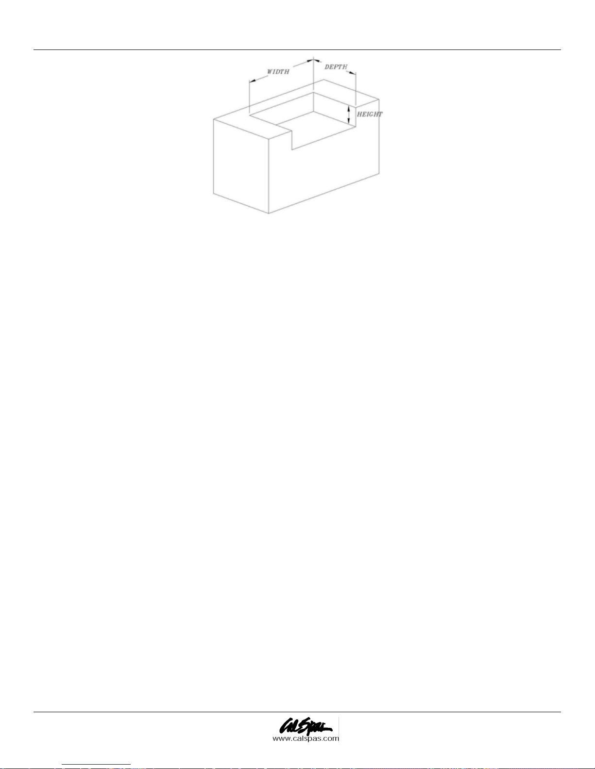
Figure 1 through Figure 4 show the four different types of cut-outs necessary for the appliances indicated.
Page 4 2006 Barbecue Owner's Manual
LTR20061004, Rev. A
Delivery and Set-Up
Figure 1: Cut-out for barbecues, side burners and slide-in accessories
Model Number Description Hardware Cutout Dimensions
Width Depth Height
BBQ872 2 Burner Grill 23 ½” 22 ½” 9 ¼”
BBQ873 3 Burner Grill 23 ½” 22 ½” 9 ¼”
BBQ874 4 Burner Grill 30 ¾” 22 ½” 9 ¼”
BBQ874C 4 Burner Convection Grill 30 ¾” 22 ½” 9 ¼”
BBQ875 5 Burner Grill 38 ¼” 22 ½” 9 ¼”
BBQ875C 5 Burner Convection Grill 38 ¼” 22 ½” 9 ¼”
BBQ870 Charcoal Grill 30 ¾” 22 ½” 9 ¼”
BBQ898 Deluxe Single Side Burner 12 ¼” 22” 7 ¾”
BBQ899 Deluxe Double Side Burner 12 ¼” 22” 7 ¾”
BBQ864P Ice Chest 12 ¼” 22” 7 ¾”
BBQ888P Food Warmer 12 ¼” 34” 7 ¾”
BBQ865P 12" Cocktail Center 12 ¼” 22” 7 ¾”
BBQ871P 18" Cocktail Center 17 ¼” 24” 10”
2006 Barbecue Owner's Manual Page 5
LTR20061004, Rev. A
Delivery and Set-Up
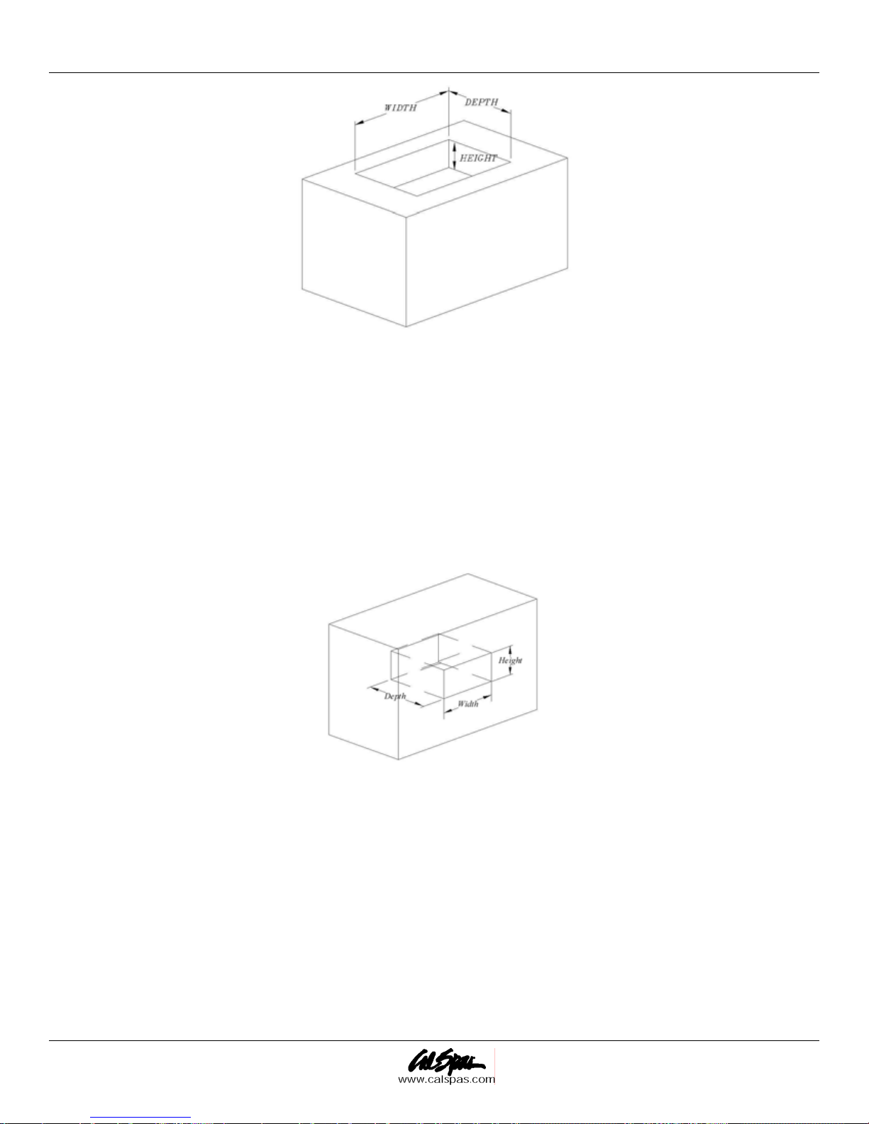
Figure 2: Flat Top Grills and Drop in Accessories
Model Number Description Hardware Cutout Dimensions
Width Depth Height
BBQ874F 4 Burner Flat Drop In Grill 38 ¼” 22 ½” >18”
BBQ852 Drop In Standard Side Burner 11 ¼” 17 ¾” >3 ½”
BBQ845P Drop In Sink 14” 14” >12”
Figure 3: Drawers
Model Number Description Hardware Cutout Dimensions
Width Depth Height
2 Drawer Storage 10 ½” 19 ¾” 17 ¼”
3 Drawer Storage 10 ½” 19 ¾” 17 ¼”
One Big One Small Drawer 10 ½” 19 ¾” 17 ¼”
BBQ862P Griddle and Griddle Storage 13 ½” 19” 2 ½”
Warming Drawer 28 ¾” 21” 10”
Page 6 2006 Barbecue Owner's Manual
LTR20061004, Rev. A
Delivery and Set-Up
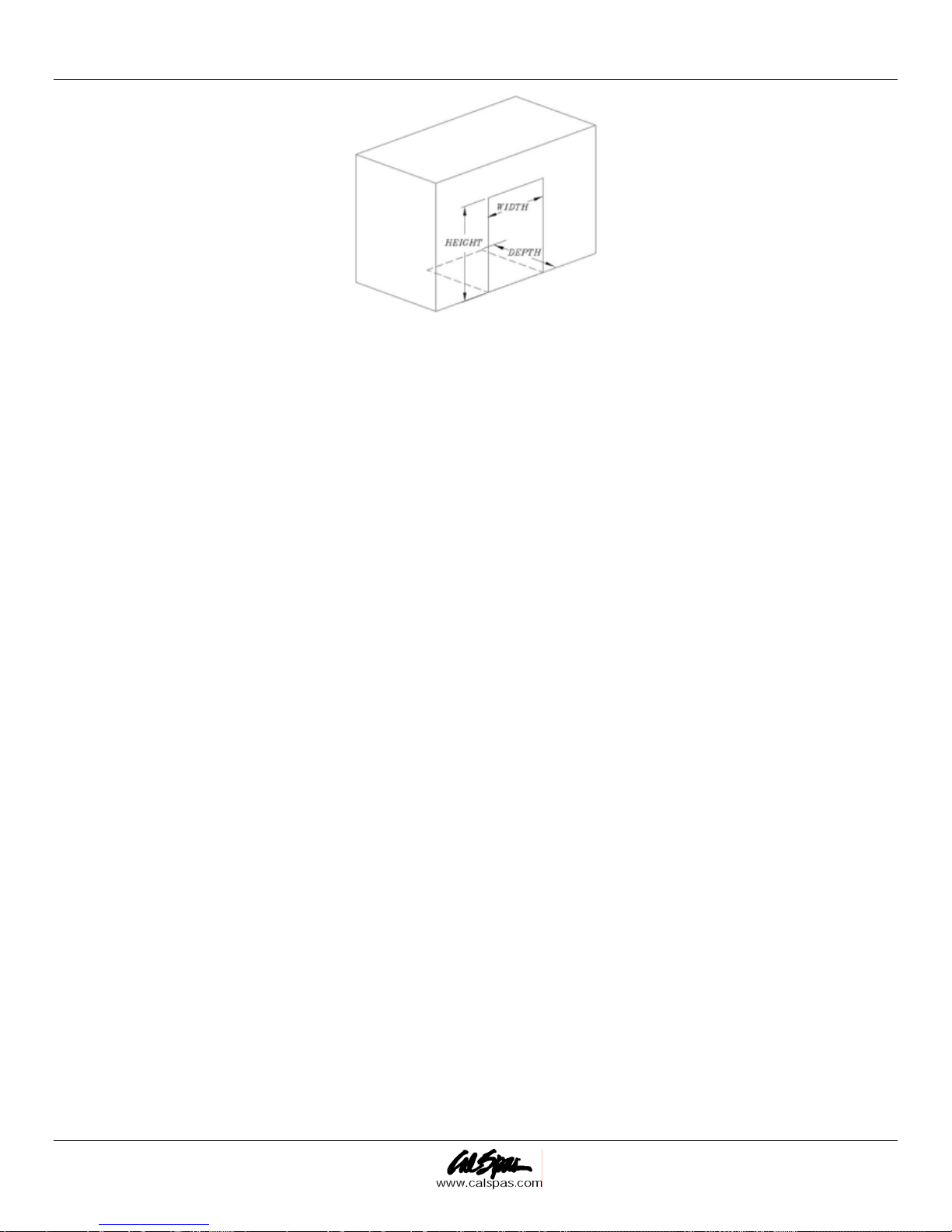
Figure 4: Refrigerators, Cocktail Centers and Access Doors
Model Number Description Hardware Cutout Dimensions
Width Depth Height
BBQ848P Deluxe Refrigerator, Glass door 24” >26" 33 ½”
BBQ847P Standard Refrigerator, SS Door 20 1/2” >23” 33”
BBQ843P Beer Tap Refrigerator 20 ¾” >23" 33”
BBQ863P 3 Pull Out Drawer, SS Refr. 23 ¾” >24” 33 ¼”
BBQ857P Propane Tank Compartment 14 ½” 18 ¼” 20 ¼”
BBQ839P-18 Single Access Door 16 ½” 2 ½” 19 ½”
BBQ839P-30 Double Access Door 28 ½” 2 ½” 19 ½”
2006 Barbecue Owner's Manual Page 7
LTR20061004, Rev. A

Delivery and Set-Up
Liquid Propane Gas Requirements and Connection
Always check the rating plate to make sure the gas supply you are hooking up to is the gas type the grill
is manufactured for.
IMPORTANT: All Cal Flame™ grills are manufactured with the highest regard to safety. For this reason, Cal
Flame™ grills are either manufactured to operate on either liquid propane (LP) or natural gas (NG) and cann ot
be converted. To verify the grill’s operating fuel check the serial number label on the right side of the chassis as
you are looking at the grill from the front. Either LP or NG will be marked on the operating tab, indicating the
proper operating fuel. Attempting to convert Cal Flame™ grills from one fuel to another may result in serious
injury and will void the warranty coverage.
NOTE: If you do not have an updated filler valve on your existing propane tank, you will need to purchase one
at your local hardware store. Without it you will not be able to attach your tank to your Cal Flame™ grill or
refill the tank at your local propane refill station.
LP Gas Hook Up
NOTE: An enclosure for an LP gas cylinder shall be vented by openings at the level of the cylinder valve and
at floor level. The effectiveness of the opening(s) for purposes of ventilation shall be determined with the LPgas supply cylinder in place. This shall be accomplished in one of the following manners:
1. One side of the enclosure shall be completely open.
2. Enclosures that have four sides, complete with a top and bottom:
a. At least two ventilation openings at cylinder valve level shall be provided in the sidewall, equally sized,
spaced at 180º (3.14 rad), and unobstructed. Each opening shall have a total free area of not less than
one square inch per pound (7.1 cm²/kg) of stored fuel capacity, and not less than a total free area of 10
square inches (64.5 cm²).
b. Ventilation opening(s) shall be provided at floor level and shall have a total free area of not less than
one square inch per pound (7.1 cm²/kg) of stored fuel capacity and not less than a total free area of 10
square inches (64.5cm²). If ventilation openings at floor level are in a sidewall, there shall be at least
two openings. The bottom of the openings shall be at floor level and the upper edge no more than 5
inches (127 mm) above the floor. The openings shall be equally sized, spaced at 180Þ (3.14 rad) and
unobstructed.
c. Every opening shall have minimum dimensions so as to permit the entrance of a 1/8 inch (3.2 mm)
diameter rod.
Remote LP Tank Requirements
• For plumbed-in LP installation, use a convertible regulator and set it for LP gas.
• Maximum line pressure for plumbed-in propane is 14” WC (3.5 kPa). Minimum line pressure for propane is
11” WC.
• The grill unit must be used with the gas pressure regulator. The regulator will control and maintain a
uniform gas pressure in the manifold. The burner orifices have been sized for the gas pressure delivered by
the regulator.
WARNING: Attempting to operate the grill unit without the gas regulator installed could cause an explosion
and possible death.
Page 8 2006 Barbecue Owner's Manual
LTR20061004, Rev. A

Delivery and Set-Up
LP Gas Cylinder Specification
Any LP gas supply cylinder used with this grill must be approximately 12 inches in diameter and 18 inches
high. The maximum fuel capacity is 20 lbs. of propane, or 5 gallons. Full cylinder weight should be
approximately 38 lbs. (43.7 lbs. nominal water capacity.) Always use the cylinder dust cap on the cylinder
valve outlet during transport and when the cylinder is not connected to the grill. This is shown below in Figure
5.
Figure 5. QCC-1 cylinder valve (shown installed on tank)
Transporting and Storing the LP Gas Supply Cylinder
Transport only one cylinder at a time. Ensure the cylinder is secured in an upright position with the control
valve turned off and the dust cap in place. Store cylinders outdoors and out of reach of children. Do not store
cylinders in a building, garage, or any other enclosed area.
Natural Gas Requirements and Connection
Requirements
Always check the rating plate to make sure the gas supply you are hooking up to is the gas type the grill
is manufactured for.
IMPORTANT: All Cal Flame grills are manufactured with the highest regard to safety. For this reason, Cal
Flame™ grills are either manufactured to operate on either liquid propane (LP) or natural gas (NG) and cannot
be converted. To verify the grill’s operating fuel check the serial number label on the left. Either LP or NG will
be marked on the operating tab, indicating the proper operating fuel. Attempting to convert Cal Flame™ grills
from one fuel to another may result in serious injury and void the warranty coverage.
IMPORTANT: Never connect the grill to an unregulated gas supply.
The installation of this appliance must conform with local codes or, in the absence of local codes, to the
national fuel gas code, ANSI Z223.1a-1998. Installation in Canada must be in accordance with the standard
CAN/CGA-B149.2, Propane Installation Code.
A licensed contractor or local gas company representative must perform all natural gas connections.
Ensure that the service supplying the grill is fitted with a shut off valve conveniently positioned near the grill
and giving ease of access.
2006 Barbecue Owner's Manual Page 9
LTR20061004, Rev. A

Delivery and Set-Up
Your Cal Flame™ grill for use with natural gas comes equipped with its own regulator that MUST NOT be
removed. If, this regulator needs to be replaced use only the type specified by Cal Flame™ for this appliance.
Natural Gas Connection
1. Remove the rear panel from the barbecue to gain access to the regulator and gas connection point.
2. Connect a suitable flex connector to the grill regulator.
3. Check the grill controls to ensure all control valves are in the full OFF position.
4. Turn on the main gas supply and check all connections for leaks using soapy water as described in “Leak
Testing Procedure” section below.
Warning: If you see bubbles in the soapy solution at any of the connections, turn off the gas supply and tighten
the connection. If tightening the connection does not seal the leak, it may be necessary to replace the flex hose.
Leak Testing Procedure
Perform a leak test at least once each year whether the gas supply cylinder has been disconnected or not. In
addition, whenever the gas cylinder is connected to the regulator or whenever any part of the gas system is
disconnected or replaced, perform a leak test.
As a safety precaution, remember to always leak test your grill outdoors in a well-ventilated area. Never smoke
or permit sources of ignition in the area while doing a leak test. Do not use a flame, such as a lighted match to
test for leaks. Use only a leak testing solution of soapy water.
1. Prepare a leak testing solution of soapy water by mixing in a spray bottle one part liquid soap to one part
water.
2. Make sure all the control knobs are in the OFF position.
3. Turn on the gas.
a. On
b. On
4. Apply the leak-testing solution by spraying it on joints of the gas delivery system. Blowing bubbles in the
soap solution indicates that a leak is present.
5. Stop a leak by tightening the loose joint or by replacing the faulty part with a replacement part
recommended by the manufacturer. Do not attempt to repair the cylinder valve if it is damaged. The
cylinder must be replaced.
6. If you are unable to stop a leak, shut off the gas supply to the grill and release pressure in the hose and
manifold by pushing in and turning any of the control valves one quarter turn counter-clockwise.
7. On LP systems, remove the cylinder from the grill.
8. Turn all control knobs back to the full OFF position.
9. Call an authorized gas appliance service technician or an LP gas dealer.
Do not use the appliance until the leak is corrected.
natural gas systems, turn the main feed valve to the grill.
LP systems, turn the cylinder valve knob counter clockwise one turn to open.
Page 10 2006 Barbecue Owner's Manual
LTR20061004, Rev. A
Assembly and Installation
Assembly and Installation
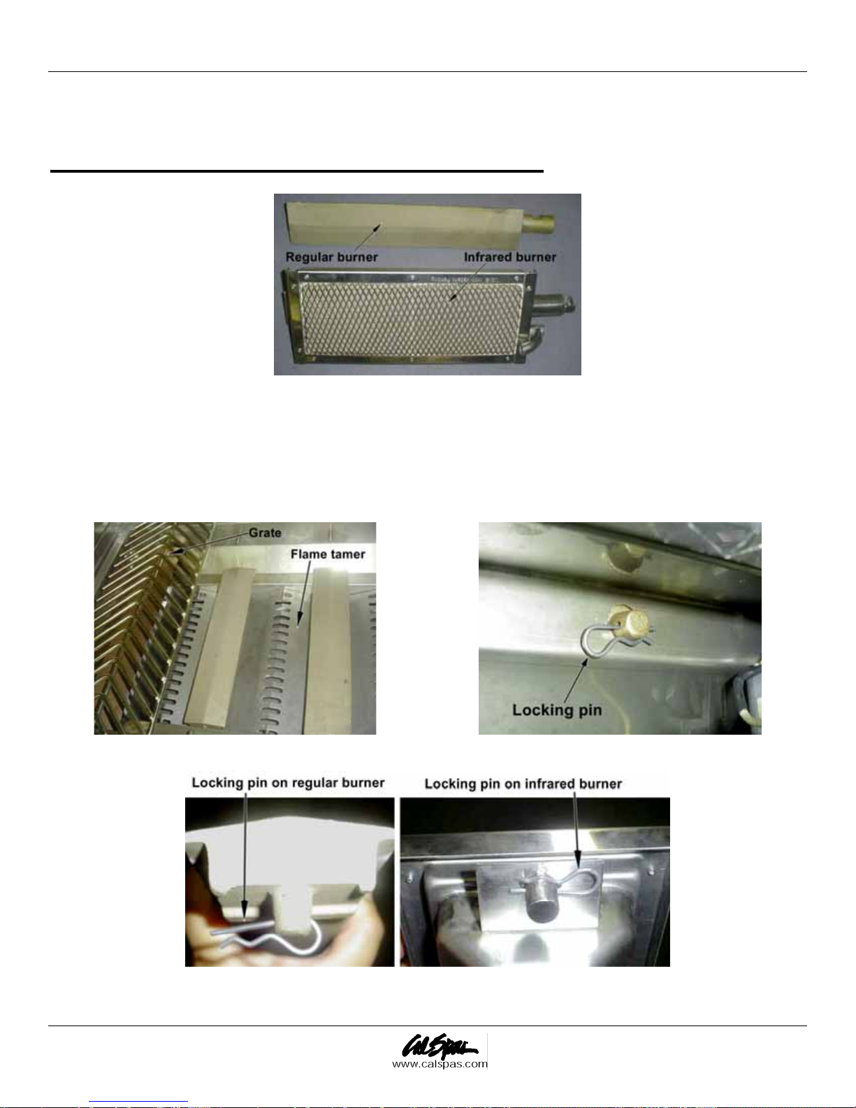
Installing and Replacing Infrared Burners
Figure 6
1. Disconnect or shut off the liquid propane or natural gas line connect to the grill, wait until the burners cool
down.
2. Open the hood, remove the grate and flame tamer on top of the brass burner you want to replace (Figure 7).
3. Through the access door underneath the grill, find the round stud and locking pin that locks the burner you
want to replace (Figure 8 and Figure 9).
Figure 7 Figure 8
4. Carefully remove the locking pin with your fingers.
2006 Barbecue Owner's Manual Page 11
LTR20061004, Rev. A
Figure 9
Assembly and Installation
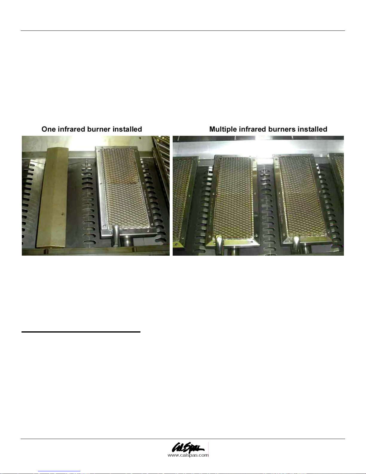
5. Raise the stud from the locking hole and move the burner forward carefully to release it from the ignition
and gas supply valve.
6. Take the burner out of the grill and store it in a safe and dry place.
7. Install the infrared burner. Align the gas inlet on the burner with the gas supply valve on the grill and torch
tube with ignition. Make sure they align perfectly. Slide the stud at the other end into the locking hole.
8. Adjust the infrared burner, make sure the burner is aligned and in position.
9. Install the locking pin. Through the access door underneath the grill, find the stud to lock the burner in
place, install the locking pin. Make sure the locking pin is secured correctly.
10. Repeat steps 2 through 9 if you want to replace other burners.
Figure 10
11. Put back the grate you just removed. (You don’t need flame tamer for infrared burners.)
12. Reconnect or turn on the gas line.
You have just successfully replaced the regular burner with infrared burner. If you want to change back to
regular burners, just follow the procedure above in reverse order.
Installing Drop-In Grills
Installing Grills in Modular Carts
IMPORTANT: Keep fingers away from where the grill will be supported on the cart. Your fingers could
become trapped and serious injury could occur.
1. Slowly lower grill unit onto the cart, making sure that screws line up with slots on top of cart (Figure 11).
Ensure that no electrical chords or gas lines become trapped between any part of the cart and any part of
the grill.
Page 12 2006 Barbecue Owner's Manual
LTR20061004, Rev. A
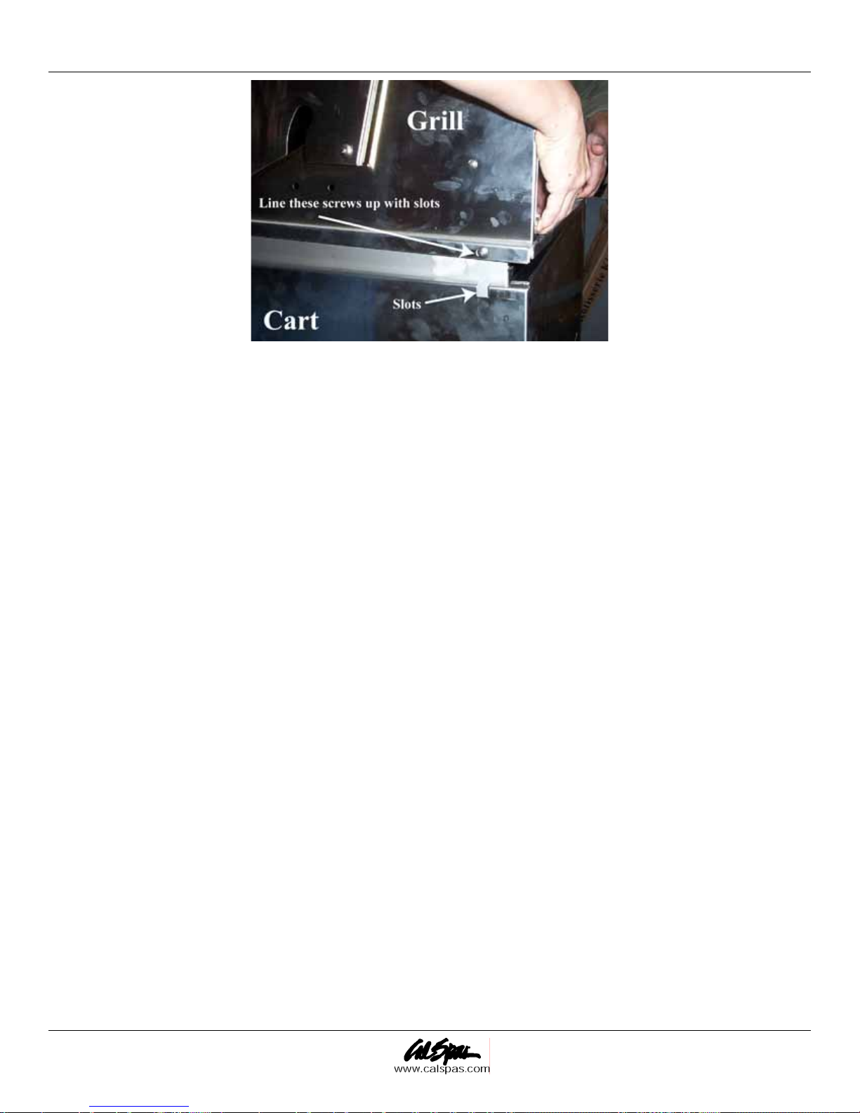
Assembly and Installation
Figure 11. Lowing the grill onto the cart
2. Grill should sit flat on cart all the way around. Gently realign cart sides to allow them to sit under outside
lip of grill.
3. Check that all burner control knobs are in the “OFF” position and attach gas connector to LP tank.
When handling LP gas line and connectors, do not allow them to come in contact with any metal surfaces of the
cart or cabinet. Do not drop LP connectors.
Installing Grills in Barbecue Islands
Before installing grill or side burner in any island or cut out, make sure that the opening is not bigger than the
outside frame of the grill unit. Grill should rest on the lip of the frame. For drop in accessories, adequate cross
ventilation must be designed into enclosure to ensure drop in grill or side burner does not become overheated.
Pay careful attention to the location of gas lines. Gas lines should be routed away from sources of heat and
should make as few bends as possible.
1. Check to see if gas line connections will be accessible when grill is installed.
a. If gas line connections are not easily accessible when the grill is installed, support the grill above
counter level and attach the gas lines to the grill. When the gas connections are made, slide the grill
into the cut out.
b. If gas line connections are accessible when the grill is installed, slide the grill into the cut out and
then attach the gas lines.
Be very careful not to kink gas lines when lowering grill or side burner into cut out.
Keep your fingers away from where the grill will be supported on counter. Your fingers could become
trapped and serious injury could occur.
2. Check to make sure the grill is level and is supported around the entire outside edge. If the grill is not
level or is unstable, use non-combustible shims under the outside lip to stabilize it.
3. Perform the leak test procedure as described earlier in this manual.
2006 Barbecue Owner's Manual Page 13
LTR20061004, Rev. A
Assembly and Installation
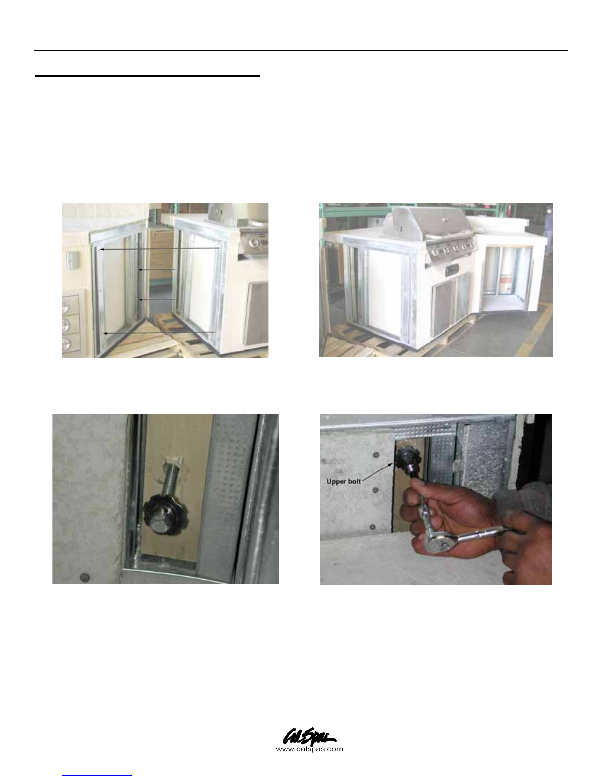
Barbecue Island Assembly
Stucco and Tile Unit Assembly
1. Place the island sections together on the ground (Figure 12 and 11).
2. Make sure the ground where the barbecue is place is as level as possible for best alignment.
NOTE: If the ground is not level, use shims to level out the island sections. This needs to be done before you
intall the bolts.
3. Connect the speakers, lights, and main power cables before sliding the sections together.
Figure 12 Figure 13
4. Insert the bolts through the pre-drilled holes from the inside of the barbecue island (total of four bolts on
each side) (Figure 14). Tighten all bolts using a 9/16” wrench (Figure 13).
Figure 14 Figure 15
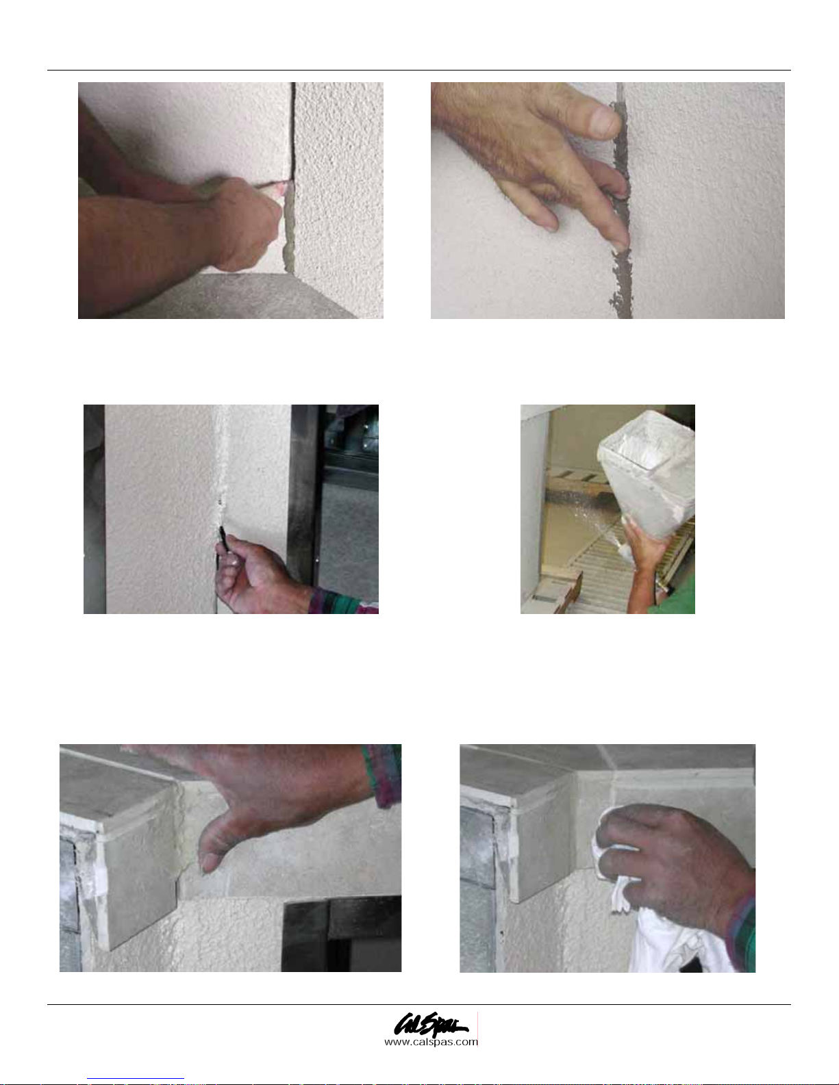
5. Prepare and fill the gap or seam line with speed set (Figure 16).
6. Using your fingertips, push and flatten out the speed set into the seam line (Figure 17).
Page 14 2006 Barbecue Owner's Manual
LTR20061004, Rev. A
Assembly and Installation
Figure 16 Figure 17
NOTE: Allow the speed set to dry before proceeding with the next step.
7. Using a small brush or hopper gun, apply stucco to the seam line (Figure 18 and 17).
Figure 18 Figure 19
8. Mix grout with water in a container.
9. Fill the tile seam line with grout using a small spatula or your finger (Figure 20).
10. Clean the grout with a damp rag (Figure 19).
11. Let the grout and stucco dry for at least three hours.
Figure 20 Figure 21
2006 Barbecue Owner's Manual Page 15
LTR20061004, Rev. A

Assembly and Installation
Rock / Stone Assembly
For Models G-2500, G-2500F, G-2600, G-3000, G-3500F, G-3600
1. Place the island sections together on the ground.
2. Make sure the ground where the barbecue is place is as level as possible for best alignment.
NOTE: If the ground is not level, use shims to level out the island sections. This needs to be done before you
place the bolts.
3. Connect the speakers, lights, and main power cables before sliding the sections together.
4. Insert the bolts through the pre-drilled holes from the inside of the barbecue island (total of four bolts on
each side). Tighten all bolts using a 9/16” wrench.
5. Prepare mortar in a container.
6. Apply mortar to the gaps left open between the island assembly (front and back).
7. Let it dry for 15 to 30 minutes and brush the area where the mortar mix was applied.
8. Prepare grout in a second container.
9. Fill the tile seam with grout using a small spatula or your finger.
10. Clean the grout with a damp rag.
11. Let the grout and mortar dry for at least three hours.
Granite Kit Instructions
Granite kits come in the following colors. Each contains various tinting colors as listed below:
Sapphire Brown New Venetian Gold Uba Tuba (Labrador) Giallo Veneziano
Black White Black Red-Brown
White Yellow White Yellow
Blue Blue Green Black
Brown White
1. Pour a small amount of epoxy resin and a small drop of each tint color on a piece of a cardboard.
NOTE: Refer to the granite tint color reference chart
2. Apply a small amount of the first tint color to the epoxy resin using a mixing stick and mix well.
3. Apply a small amount of the second tint color to the epoxy resin and mix well.
4. Apply a small amount of the next tint colors, one at a time to the epoxy resin and mix well.
5. Compare color of mixed epoxy resin with the color of the counter top.
6. If the colors do not match, add small amounts of tint color (one at a time) and mix until the resin mixture
matches the color of the granite top.
7. Add a small amount of hardener to the matching resin mixture and mix well.
8. Quickly fill one portion of the seam line with the epoxy mixture. Remove the excess epoxy material from
the seam line using a razor blade.
9. Let the epoxy material cure for five minutes.
10. Pour a small amount of epoxy and hardener separately on a piece of cardboard.
11. Mix the epoxy material well with the hardener.
Page 16 2006 Barbecue Owner's Manual
LTR20061004, Rev. A

Assembly and Installation
12. Quickly apply the epoxy mixture to the seam line. Remove the excess epoxy material from the seam line
using a razor blade.
13. Let the epoxy material cure for five minutes.
14. Repeat the previous steps until all the seam line is filled with epoxy mixture.
15. Clean the surface of the seam line with acetone.
Connecting Modular Carts
Modular carts consists of main center modular, side modular, corner connection modular and end shelf modular.
Individual modular cart comes in a carton box pre-assembled. Customers are required to piece together the
individual modular using the hardware supplied when they install the modular cart system.
1. The modular cart system is designed for outdoor use only. It’s dangerous to use the system inside or at
place without good ventilation.
2. Choose a place outdoor you want to use and store the system.
3. Unpack the carton boxes include the main center modular, optional side modular and corner connection
modular.
4. Find the connection hardware (screws and nuts) in the cartons.
5. First connect the corner connection modular with the main center modular on both side (if applicable) Make
sure the center modular and connection modular are aligned.
6. Connect the side modular with the corner connection modular on both sides (if applicable). Make sure all
the modular are perfectly aligned.
7. Add the end shelf on both sides of side modular (if applicable)
8. If use propane as fuel, connect the propane tank with main center modular and a separate propane tank for
side modular (if applicable)
9. If using natural gas, connect the center modular with the gas line, and also side modular (if applicable). A
manual shut-off valve is recommended for safety reasons.
10. Connect tap water and drainage line (if applicable)
Installing Barbecue Cart End Shelves
1. Prepare the installation of handle: 2 hex screws, 2 washers
2. Use finger to thread the hex screws and washers into the threads on both ends of the handle.
3. Use ratchet to tighten the hex screws on both ends. The handle has been installed onto the shelf.
4. Take the three screws off on both sides of the cart to install the mounting bracket.
5. Install the mounting brackets on both sides. Make sure the mounting brackets are in the correct orientation.
Two mounting brackets have been installed onto the cart.
6. Slides the shelf into the brackets from bottom.
7. Make sure to slide into the brackets on both side evenly.
8. Slide the shelf fully onto the mounting brackets.
9. Lift and rotate the shelf so it slide back into the brackets.
10. Keep the shelf in the normal open position.
11. Prepare to install stop brackets under the mounting brackets on both sides.
2006 Barbecue Owner's Manual Page 17
LTR20061004, Rev. A
 Loading...