

Caleffi solar iSolar 257 series, iSolar1 257210A, iSolar2 257220A, iSolar3 257230A, iSolarPlus 257260A Specifications

Differential temperature controllers
US
C
iSolar
257 series
Function
A multi-functional temperature differential controller with add-on system functions, the iSolar series
can be used for a wide variety of applications and has inputs for four PT1000 sensors. Preset factory
defaults are defined for control of a standard solar water heating system with a second relay (some
models) to divert any surplus heat. The auxiliary relay can be used to maintain the tank temperature,
protect the system from overheating, or use another source to heat the storage tank.
This controller features a large Liquid Crystal Display (LCD) user interface with three function keys.
The easy-to-use icons assist to operate and customize a solar heating system.
Tested and Approved by TÜV Rheinland as an approved U.S. Nationally Recognized
Testing Laboratory (NRTL) Exceeds or is equivalent to:
UL 60730-1A
US
C
Product range
Code 257210A iSolar1 controller with 1 standard output relay for pump control, includes 3 temperature sensors
Code 257220A iSolar2 controller with 1 electronic output relay for pump speed control, includes 3 temperature sensors
Code 257230A iSolar3 controller with 2 standard output relays for pump control, plus valve or second pump control, includes 3 temp. sensors
Code 257260A iSolarPlus controller with 2 electronic output relays for pump speed control, plus valve or second pump control, includes 3 sensors
CAN/CSA E60730-1
CALEFFI
Technical specifications
Housing plastic: PC-ABS
Protection type: Indoor only
Mounting: wall or in 255 series pump station
Display: LCD with symbols and text
Interface: three soft push buttons
Inputs: 4 temperature sensors
Outputs: 1 or 2 electronic or standard relays
Switching relay capacities: 2 (1) A 115V
Power supply: 115 V - 60 Hz
Bus interface: V-Bus
Performance
ΔT adjustment range: 2···40º Ra (1···20ºK)
Min. temperature differential 2º Ra (1ºK)
Hysteresis: 2º Ra, ± 1º Ra (1ºK, ± .5ºK)
Max. tank temperature range: 35···205°F (2···95ºC)
Max. collector temperature range: 210···375°F (100···190ºC)
Emergency shut down of the collector: 230···395°F (110···200ºC)
Min. collector temperature range: 50···195ºF (10···90°C)
Antifreeze temperature option: 15···50°F (-10···10ºC)
kWh (BTU) flow input: 0···5 gpm (0···20 lpm)
Agency approvals cTÜVus
Temperature sensors
Platinum RTD type: 1,000 ohm
Collector sensor working range: -58···355ºF (-50···180°C)
Tank sensor working range: 15···175ºF (-10···80°C)
Length of collector cable: 60 in. (1.5 m)
Length of tank sensor cable: 95 in. (2.5 m)
Resistance values for sensors subject to the temperature
°F 14 23 32 41 50 59 68 77 86
961 980 1000 1019 1039 1058 1078 1097 1117
Ω
°F 95 104 113 122 131 140 149 158 167
1136 1155 1175 1194 1213 1232 1252 1271 1290
Ω
°F 176 185 194 203 212 221 230 239 248
1309 1328 1347 1366 1385 1404 1423 1442 1461
Ω
Dimensions
A
Code
250041A
B
A
4
3/8”
B
6 3/4”
C
D
C
6”
D
2”
Weight (lb)
0.9
Characteristics
User-friendly operation
System screen LCD display
!
Ì
"
"
F
R
with 16-segment display and
8 symbols for system status
Operating LED control lamp
3 push-button controls
– +
SET
Attractive design and compact
dimensions
Easy to install
+
S
tandard operation functions
∆T control - When the switch-on difference is reached, the pump is activated until
the differential temperature drops below.
Maximum tank temperature - When the adjusted maximum tank temperature is
exceeded, the pump switches off.
Collector emergency shutdown - If adjusted collector temperature is exceeded,
the solar pump is switched off.
System cooling - If the temperature rises to the maximum collector temperature
the solar pump remains on until this temperature drops.
Minimum collector temperature - a minimum set temperature which must be
exceeded before the solar pump is switched-on.
Antifreeze function - If the adjusted temperature drops, the solar pump is switched
on to protect the fluid from freezing.
Tank cooling function - In the evening, the solar pump continues running until
the storage tank is cooled down.
Tube collector function - The controller measures an increase of heat rise in the
collector and adjusts operating time for maximum efficiency.
Heat generation measurement kWh (BTU) - The heat generated is measured by
the volume flow and the temperature of feed and return sensors.
Operating hours counter - Operating hours counter stores the solar operating
hours of the respective relay.
Manual operating mode - For control and servicing, the operating mode of the
controller can be switched manually.
Advanced operation functions (some two-relay models)
Heat dumping function - Heat dumping function works independently from the
solar operation and activates the second relay.
Backup heating function - Backup heating function works independently from
the solar operation and activates the second relay.
Second independent ∆T control - The switch on and off temperatures can be
adjusted separately.
Priority tank / tank rotation - The controller checks the tank temperatures and
rotates or gives priority to charging tanks.
East / West collectors - Two separate ∆T controls activate each solar pump
based on collectors and the one-tank differential temperature.
Pump speed control functions
Pump speed control can improve system efficiency by reducing the flow to
the collectors on cloudy days to improve solar thermal transfer and reduce
electrical consumption. This is achieved by the differential temperature
value between the collectors and storage tank.
If the value for the ΔT switch-on is reached (e.g. ΔT on = 9º ), the pump
will start with 100% pump speed for 10 seconds, then reduce the speed to
the adjusted minimum pump speed (min. pump speed = 30 %, adjustable).
If the temperature difference reaches the set value (e.g. ΔT Set = 18º ),
pump speed will increase by 10 %. At any further rise of 3º ΔT the pump
speed will increase by 10% until the maximum of 100% is reached.
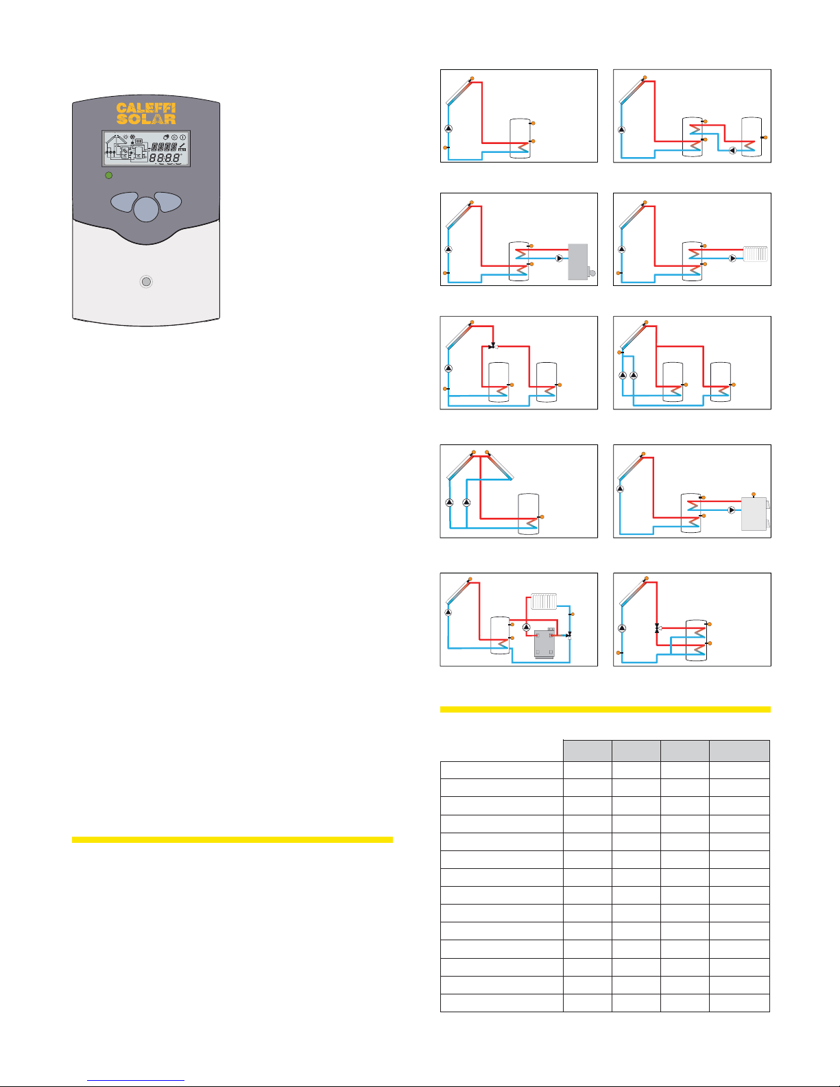
Selectable systems
S1
R1
S4 / TRL
Standard system with 1 tank, 1 pump and 3
sensors. S4 / TRF can be used as BTU meter
S1
R1
S4 / TRL
Solar system and backup heating with 1 tank, 3
sensors. S4 / TRF can be used as BTU meter
S1
Tank 1 Tank 2
R1
S4 / TRL
2-tank-solar system with valve logic, 3
sensors, 1 solar pump and 3-way valve.
Sensor S4 / TRF can used as BTU meter
Solar system with east-west collectors,
1 tank, 3 sensors and 2 solar pumps.
System and heating circuit pre-heat with
1 tank, 4 sensors, 1 solar pump and 3-way
valve for heating circuit.
S3
S1
R1
R2
S1
R1
R2
S2 S3
S3
S2
S3
S2
S3
R2
S2
S2
S4
R2
S1
R1
System and heat exchange with an existing
tank with 1 tank, 4 sensors and 2 pumps
S1
R1
S4 / TRL
Solar system and heat dumping with 1 tank, 3
sensors. S4 / TRF can be used as BTU meter
S1
S4 / TRL
R1 R2
2-tank solar system with pump logic, 3
sensors and 2 solar pumps
S1
R1
System with backup heating by wood boiler
with 1 tank, 4 sensors, 1 solar pump and
1 pump for backup heating.
S1
R1
R2
S4 / TRL
System and tank charge in layers with 1 tank,
3 sensors, 1 solar pump and 3-way valve.
Sensor S4 / TRF can be used as BTU meter
S3
Tank 1
S2
S3
S2
Tank 1 Tank 2
S2
S3
S2
S3
S2
Tank 2
R2
R2
S3
S4
R2
S4
Model selection
iSolar 1 iSolar 2 iSolar 3 iSolar Plus
Selectable programs 1 1 2 9
Electronic relayy0102
Standard relay 1 0 2 0
Pump speed control no yes no yes
Operating hours counter yes yes yes yes
kWh (BTU) measurement yes yes yes yes
V-bus for data recorder yes yes yes yes
PC-interface RS232 yes yes yes yes
Heat dumping function no no yes yes
Backup heat function no no yes yes
Additional ΔT control no no no yes
Two-tank priority no no no yes
Clock with scheduling no no no yes
A062752A013752A022752A012752edoC
 Loading...