

Page 1
NA10333
www.caleffi.com
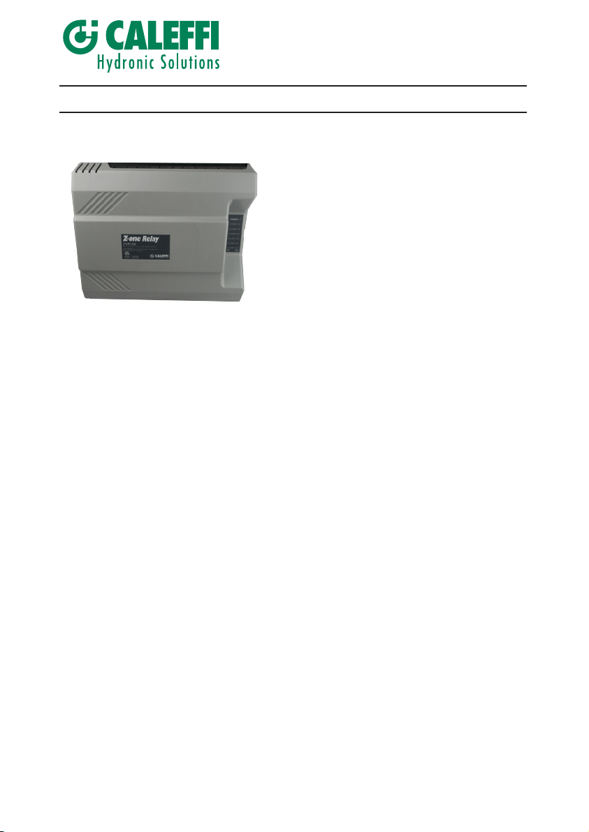
Z-one™ Relay Multi-Zone Valve Control
© Copyright 2014 Caleffi
• Compatible with low voltage 2, 3, or 4 wire thermostats
• R, W, C and TT Comm dual labeling at thermostat terminals
• Z-oneLink unlimited zone expansion
• Selectable priority with 1 hour time-out feature
• System pump status selectable during priority
• Circulator will start only after the zone valve end switch is closed
• Dry contacts for DHW (ZR/ZC), capable of switching line voltage
• Large terminal connections
• High Capacity 40 VA Transformer standard for 3 and 4 zone models-expandable to 80 VA,
and 80 VA for the 6 zone model
• Automatic resettable fuse
• Controls system pump, secondary pump, and priority pump
• Front LED Lights
• 100% Factory tested with 3 year warranty
• ETL Approved
Product Range
Code ZVR103 Z-one™ Relay switching relays...............................................................three zone
Code ZVR104 Z-one™ Relay switching relays.................................................................four zone
Code ZVR106 Z-one™ Relay switching relays...................................................................six zone
Technical specifications
ZVR10X series
Function
The ZVR series is a multi-zone zone valve and boiler
operating control for multiple zone hydronic heating or
cooling systems. The ZVR series interfaces with low
voltage thermostats, or any other low voltage controllers
having a switching action. The ZVR series controls up
to 3, 4, 5 or 6 zones, depending on model selected.
In addition, a system circulator pump and secondary
pump is turned on whenever any zone calls for heat.
LED indicators provide functional status and easy
system troubleshooting. The ZVR series is a perfect
match with Caleffi’s Z-one™ motorized zone valves.
Materials
Housing plastic: ABS
Front display lights: LCD
Electrical Knockouts: (12) 1/2" size
Performance
Power supply: 120 VAC, 50/60 Hz
Transformer voltage: 24 VAC
Maximum transformer load: 40 VA (ZVR103/4), 80 VA (ZVR106)
Electrical switch rating: 20A Max Combined
Electrical switch rating, ZR/ZC, DHW, XX: 120 VAC, 2A each
Electrical switch rating pumps: 120 VAC, 5A each
Resettable Fuse: automatic
Maximum temperature: 110°F (43°C)
Maximum humidity: 90% non-condensing
Approvals: Certified to CSA C22-2 No.24
Conforms to UL Standard 873
Page 2
Dimensions
POWER
ZONE 1
ZONE 2
ZONE 3
ZONE 4
ZONE 5
ZONE 6
ZVR106
Six zone switching - Input: 120VAC 50/60Hz 20A MAX
Conforms
to UL 873
4009064
CAUTION:
RISK OF ELECTRIC SHOCK - DISCONNECT ALL
INPUT POWER PRIOR TO SERVICING
Milwaukee, WI 53208 USA
POWER
ZONE 1
ZONE 2
ZONE 3
ZONE 4
ZONE 5
ZONE 6
T-STAT
CALL
VALVE
OPEN
A
B C
C
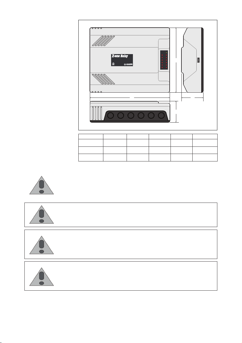
Code Zones A B C Wgt. (lbs)
ZVR103 3
ZVR104 4
ZVR106 6
9
9
1/4" 11" 3"
9
1/4" 11" 3"
3.2
3.2
3.2
1/4" 11" 3"
SAFETY INSTRUCTION
This safety alert symbol will be used in this manual to draw attention to safety
related instructions. When used, the safety alert symbol means ATTENTION!
BECOME ALERT! YOUR SAFETY IS INVOLVED! FAILURE TO FOLLOW
THESE INSTRUCTIONS MAY RESULT IN A SAFETY HAZARD.
CAUTION: All work must be performed by qualified personnel trained in the
proper application, installation, and maintenance of systems in accordance
with all applicable codes and ordinances.
CAUTION: Electrical shock hazard. Disconnect power before installation to
prevent electrical shock or equipment damage. Make sure all connections
are in accordance with the electrical wiring diagram and in accordance with
national and local electrical codes.
WARNING: Avoid electrical noise interference. Do not install near large
conductors, electrical machinery, or welding equipment. Avoid locations
where excessive moisture, corrosive fumes, vibration, or explosive vapors are
present.
Caleffi shall not be liable for damages resulting from misapplication or misuse of it products.
Page 3
Installation
Inspection
Inspect packages for damage. If damaged, notify the appropriate carrier
immediately. If undamaged, open the package and inspect the device for
obvious damage. Return damaged products.
• Use only copper conductor supply wire suitable for at least 105° C
• All circuits must have a common disconnect and be connected to the
same pole of the disconnect
Maintenance and Repair
The Caleffi Z-one™ multi-zone valve control comes with a resettable
fuse and requires no maintenance. If control fails or is damaged, replace
control with functional one.
Mounting
Mount the Caleffi Z-one™ switching relay box to a suitable surface.
Slotted holes are provided for mounting purposes. Do not mount to a
surface that exceeds 115°F (45°C). The unit must be only located in dry
interior locations. It is not suitable for installation in hazardous locations
and should not be placed close to any electromagnetic fields.
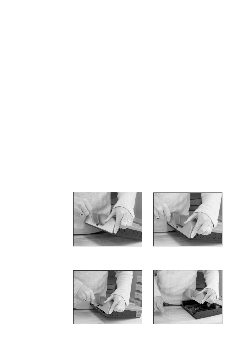
Cover removal
Hold either the left or the right
end of the box up and at an
angle. Use body for stabilizing
relay box.
Roll cover off base.
Insert screwdriver and push tab
inward, cover should release from
base.
Page 4
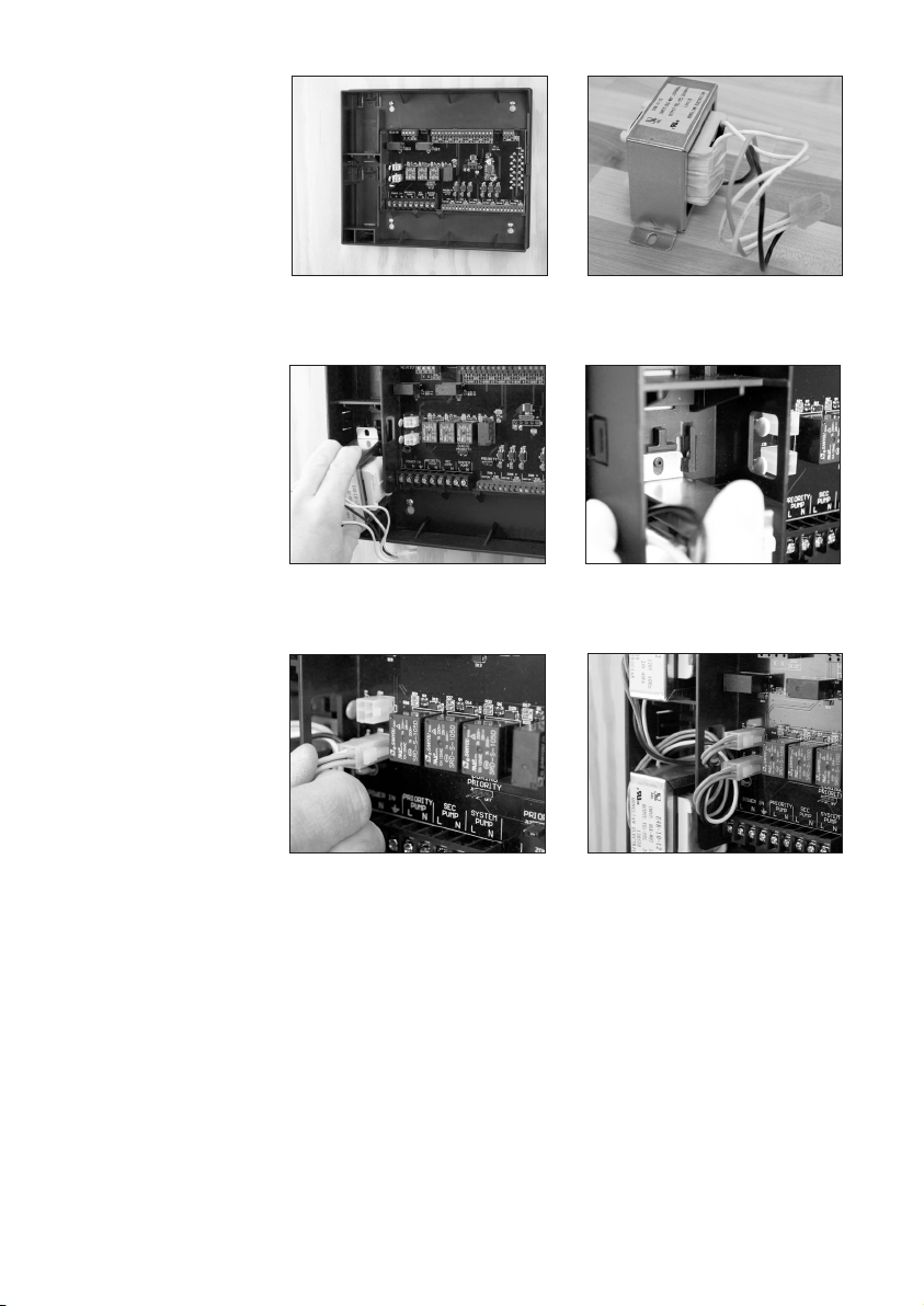
Transformer
Installation
Mount box on stable surface
using level.
Slide bottom end of transformer
into bottom latch.
Feed wiring through hole near the
top of the transformer and insert
transformer plug into the socket.
Remove transformer(s) from
packaging.
Snap top of transformer into latch
arms.
Repeat process for 2nd
transformer if six valve relay box.
Page 5
T-STAT 4
C
OM
T-STAT 5
C
R
W
T T COM
T-STAT 6
R
W
T T COM
6 Zone
ZVR106
MASTER SLAVE
C
COMMS
D
P
T-STAT 3
C
R
W
T T COM
T-STAT 4
C
R
W
T T COM
T-STAT 5
C
R
W
T T COM
T-STAT 6
C
R
W
T T COM
6 Zone
ZVR106
PRIORITY
MASTER SLAVE
T-STAT 2
C
R
W
T T COM
T-STAT 3
C
R
W
T T COM
C
W
T-STAT 4
C
R
W
T T COM
T-STAT 5
C
R
W
T T COM
T-STAT 6
C
R
W
T T COM
PWR
TSAT1 ZONE1
COMMS
D
P
C
W
6 Zone
ZVR106
TSAT1 ZONE1
TSAT2 ZONE2
TSAT3 ZONE3
TSAT4 ZONE4
TSAT5 ZONE5
TSAT6 ZONE6
ZONE 1
END
SWITCH
MOTOR
PRIORITY
ZONE 2
END
SWITCH
MOTOR
ZONE 3
END
SWITCH
MOTOR
ZONE 4
END
SWITCH
MOTOR
ZONE 5
END
SWITCH
MOTOR
ZONE 6
END
SWITCH
MOTOR
ON OFF
MASTER SLAVE
C
COMMS
D
P
T-STAT 3
C
R
W
T T COM
T-STAT 4
C
R
W
T T COM
T-STAT 5
C
R
W
T T COM
T-STAT 6
C
R
W
T T COM
PWR
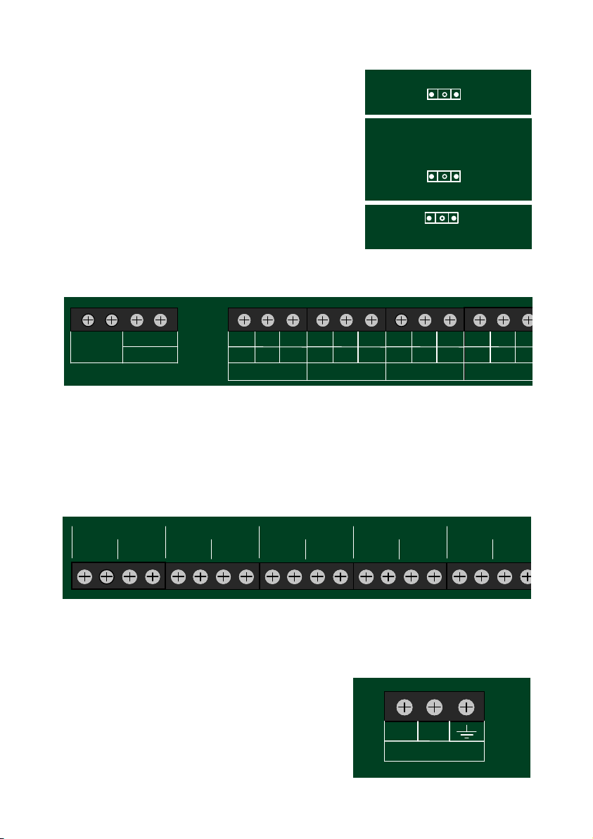
Jumper set up
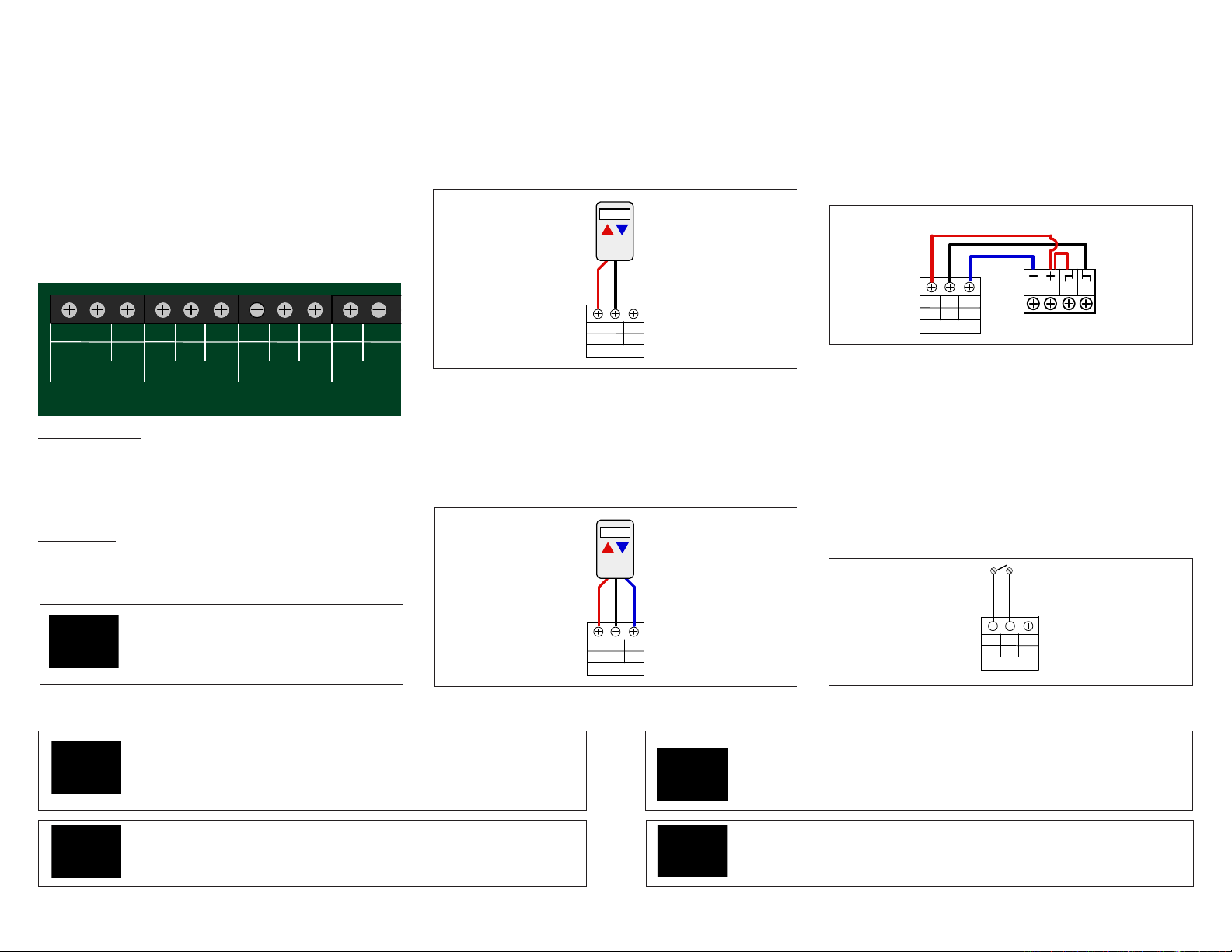
The jumpers on the ZVR series can be positioned for the
following operations.
Priority ON / Priority OFF: When priority jumper is ON, upon
demand, zone 1 will operate as priority and all other zones are
temporarily switched off (with 1 hour time-out). When priority
mode is OFF, any zones that were active when zone 1 was
switched on will remain on.
Status During Priority ON / Status During Priority OFF: When
status jumper is ON, the system pump will continue to operate
during priority.
Master / Slave: allows for unlimited expansion to additional ZVR
relays.
Wiring terminals
X X
DHW
ZR/ZC
R
W
T T COM
T-STAT 1
When a zone has a demand from a thermostat (T T or R W) the control will send 24 VAC to the
corresponding zone valve. When the zone valve end switch closes, the primary pump will switch
on and the (X X) dry contacts will close to signal the boiler of a heating demand. Zone 1 can be
used for priority (either a priority pump or valve). When the priority jumper is ON, a demand from
T-Stat1 will activate 24VAC to valve 1 and the priority pump will switch on after the end switch
closes (requires a jumper in the end switch terminals if a valve is not used). The DHW (ZR/ZC)
dry contact will also close. Depending upon "Status During Priority" jumper, the system pump will
either be ON or OFF.
R
C
W
T T COM
T-STAT 2
C
PRIORITY
ON OFF
STATUS
DURING
PRIORITY
ON OFF
MASTER SLAVE
R
W
T T COM
T-STAT 3
R
C
T T C
W
Large screw terminals connections makes wiring easy with three pump screw terminal connections.
Pump terminals connection have 120 VAC outputs for simplified pump connections. Zone valve
connections can be 2, 3 or 4 wire.
Z-oneLink unlimited expansion allows adding addition ZVR
series relay controls to a Master ZVR. Communication is
accomplished by connecting three wires (bell or thermostat
wire) to the communication terminals located in the upper
right hand corner. The jumper is positioned to Master / Slave
position. A demand for heat from any zone will fire the boiler
and start the pump.
D
COMMS
P
Page 6
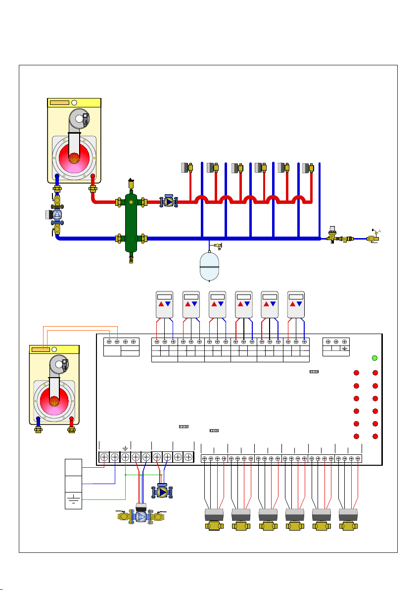
Example Wiring Diagram
Please reference Z-one™ Relay wiring guide for complete listing of wiring diagrams.
ModCon boiler with
Primary/Secondary
mod/con!
boiler
PRIORITY!
pump
X X
POWER IN
L
ZV1
SECONDARY!
pump
DHW
ZR/ZC
N
PRIORITY
PUMP
L
N
T T COM
T-STAT 1
SEC PUMP
N
L
CRW
STATUS
DURING
PRIORITY
SYSTEM
L
T T COM
T-STAT 2
ON OFF
PUMP
N
CRW
PRIORITY
MOTOR
T T COM
T-STAT 3
ZVR106
6 Zone
ON OFF
ZONE 1
END
SWITCH
CRW
MOTOR
T T COM
T-STAT 4
ZONE 2
SWITCH
ZV4ZV3ZV2 ZV5 ZV6
CRW
CRW
T T COM
T-STAT 5
ZONE 3
END
END
SWITCH
MOTOR
MOTOR
T T COM
T-STAT 6
ZONE 4
END
SWITCH
CRW
MASTER SLAVE
MOTOR
ZONE 5
END
SWITCH
D
COMMS
P
MOTOR
ZONE 6
VENT
TSAT1 ZONE1
TSAT2 ZONE2
TSAT3 ZONE3
TSAT4 ZONE4
TSAT5 ZONE5
TSAT6 ZONE6
END
SWITCH
PWR
L
N
PRIORITY!
pump
SECONDARY!
pump
ZV1
ZV4ZV3ZV2 ZV5 ZV6
Page 7
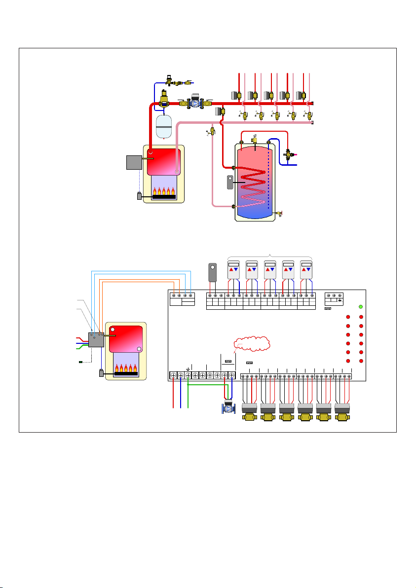
Noncondensing boiler with
outdoor reset and indirect DHW
VENT
low flow resistance boiler
SYSTEM!
pump
ZV1
DHW!
aquastat
ZV2
ZV3
indirect DHW tank
ZV4
ZV5
ZV6
space
heating
demand
domestic water
heating demand
boiler!
reset!
controller
L
N
G
outdoor!
temperature!
sensor
CRW
STATUS
DURING
PRIORITY
SYSTEM
PUMP
N
SYSTEM!
pump
T T COM
space heating thermostats
CRW
T T COM
THM 2
THM 3
ZRV106
6 Zone
Z6V
set to ON
PRIORITY
ZONE 1
END
SWITCH
MOTOR
ZV1 ZV2 ZV4 ZV5 ZV6ZV3
CRW
T T COM
MOTOR
ZONE 2
THM 4
SWITCH
D
CRW
SWITCH
P
PWR
COMMS
Master/Slave
THM1 ZONE1
THM2 ZONE2
THM3 ZONE3
THM4 ZONE4
THM5 ZONE5
THM6 ZONE6
ZONE 5
ZONE 6
END
SWITCH
END
SWITCH
MOTOR
END
MOTOR
CRW
CRW
T T COM
T T COM
THM 6
THM 5
ZONE 3
END
ZONE 4
END
SWITCH
MOTOR
MOTOR
DHW!
aquastat
DHW
X X
ZR/ZC
T T COM
THM 1
T T
ZC
ZR
PRIORITY
L
POWER IN
SEC PUMP
PUMP
L
N
N
L
L N G
Page 8
CALEFFI
pump
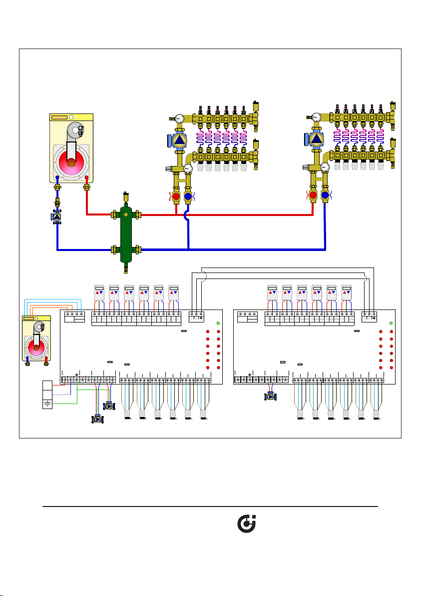
Modern boiler with Primary/Secondary and
two secondary pumps
SYSTEM!
pump
T T COM
T-STAT 1
SECPUMP
L
"B"!
pump
A10A9A8 A11 A12A7
D
CRW
CRW
PRIORITY
SYSTEM
L
STATUS
DURING
ON OFF
PUMP
T T COM
T-STAT 2
N
MOTOR
T T COM
T-STAT 3
PRIORITY
ZONE1
ZVR106
6 Zone
ON OFF
END
SWITCH
CRW
CRW
CRW
T T COM
T T COM
T-STAT 4
T-STAT 5
ZONE2
ZONE3
END
END
SWITCH
SWITCH
MOTOR
MOTOR
MOTOR
CRW
N
T T COM
T-STAT 6
ZONE4
SWITCH
P
PWR
COMMS
TSAT1 ZONE1
MASTER SLAVE
TSAT2 ZONE2
TSAT3 ZONE3
TSAT4 ZONE4
TSAT5 ZONE5
TSAT6 ZONE6
ZONE5
ZONE6
END
END
END
SWITCH
SWITCH
MOTOR
MOTOR
"A"!
pump
A4A3A2 A5 A6A1
DHW
X X
ZR/ZC
PRIORITY
POWERIN
PUMP
N
L
N
L
T T COM
T-STAT 1
SECPUMP
L
CRW
SYSTEM
PRIORITY
L
T T COM
T-STAT 2
STATUS
DURING
ON OFF
PUMP
CRW
CRW
T T COM
T T COM
T T COM
T-STAT 3
T-STAT 4
T-STAT 5
ZVR106
6 Zone
PRIORITY
ON OFF
ZONE1
ZONE2
N
MOTOR
ZONE3
END
END
SWITCH
END
SWITCH
SWITCH
MOTOR
MOTOR
CRW
N
D
CRW
T T COM
T-STAT 6
ZONE4
P
PWR
COMMS
TSAT1 ZONE1
MASTER SLAVE
TSAT2 ZONE2
TSAT3 ZONE3
TSAT4 ZONE4
TSAT5 ZONE5
TSAT6 ZONE6
ZONE5
ZONE6
END
END
SWITCH
END
SWITCH
SWITCH
MOTOR
MOTOR
CRW
MOTOR
DHW
X X
ZR/ZC
PRIORITY
POWERIN
PUMP
N
L
N
L
L
N
SYSTEM!
pump
"A"!
A1
A4A3A2 A5 A6
"B"!
pump
A10A9A8 A11 A12A7
Caleffi North America, Inc.
3883 West Milwaukee Road
Milwaukee, WI 53208
T: 414.238.2360 F: 414.238.2366
Page 9
WIRING GUIDE
The ZSR101 is a versatile single relay control with two outputs for operating a 120 VAC pump with boiler enable, or two 120
VAC devices without boiler enable. Features include rear knock outs for 4x4 junction box mounting, convenient pre-installed
jumper for pump operation, and 10 amp total load rating.
The ZSR Series of controls is for zoning using pumps. Up to 6 zone pumps (model dependent) along with a primary pump
can be operated. Zone priority is selectable with 1-hour time-out feature. Other features include pump exercising, selectable
post purge, and 3 pump ground terminals for simplied wiring.
Certified to CSA C22-2 No.24
Conforms to UL Standard 873
4009064
Form 031914 rev.1
The ZVR Series of controls is for zoning using zone valves. Up to 6 valves (model dependent), along with a system pump,
secondary pump(s), and primary pump can be operated. Zone priority is selectable with 1-hour time-out feature. System
pump status (on\off) during priority is also selectable. Replaceable snap-t 40 VA transformer standard for 3 & 4 zone models – expandable to 80 VA with 2nd transformer. 6 zone model has two 40 VA (80 VA) transformers.
Page 10

2
Page 11

INDEX
Z-one Relay thermostat connections
Thermostat wiring ........................................................................................................................................................................... 3
ZSR101 - single zone relay
Product overview
Operation and cover removal
A1 - Single thermostat ...................................................................................................................................................................................6
A2 - Multiple thermostats ....................................................................................................................................................................8
A3 - Single master thermostat, with TRVs, variable speed pump .................................................................................................... 10
ZSR103, ZSR104 & ZSR106 - multi-zone pump relay
Product overview ........................................................................................................................................................................... 12
Circuit board ..................................................................................................................................................................................13
Cover removal ................................................................................................................................................................................ 14
Product details
B1 - Mod/Con boiler, hydro separator or buffer tank, zone pumps
B2 - Traditional boiler, indirect DHW w/ priority, zone pumps .......................................................................................................... 18
B3 - Mod/Con boiler, primary loop, closely spaced tees, zone pumps ............................................................................................ 20
ZVR103, ZVR104 & ZVR106 - multi-zone valve control
Product overview ........................................................................................................................................................................... 22
Circuit board ..................................................................................................................................................................................23
Cover removal, Transformer Installation .................................................................................................................................................24
Product details ............................................................................................................................................................................... 25
C1 - Mod/Con boiler, hydro separator, zone valves
C2 - Mod/Con boiler, indirect DHW on primary side of hydro sep, zone valves
C3 - Mod/Con boiler, indirect DHW on load side of hydro sep, zone valves .................................................................................... 30
C4 - Mod/Con boiler, indirect DHW on primary side of hydro sep, master and slave control ........................................................... 32
C5 - Traditional boiler, indirect DHW (no priority) with valve ............................................................................................................. 34
C6 - Traditional boiler with reset control, priority indirect DHW with valve
C7 - Mod/Con boiler, hydro separator, zone valve (more than 6), multiple secondary pumps
............................................................................................................................................................................ 4
........................................................................................................................................................................5
............................................................................................................................................................................... 15
................................................................................................. 16
........................................................................................................................ 26
............................................................................... 28
........................................................................................ 36
.......................................................... 38
Caleffi shall not be liable for damages resulting from misapplication or misuse of it products.
3
Page 12
Z-one Thermostat Connections
COMMS
D
P
T-STAT 4
C
COM
T-STAT 5
C
R
W
T T COM
T-STAT 6
C
R
W
T T COM
PWR
ZONE1
PWR
PWR
PWR
ZONE1
WR
2-Wire Thermostats
4-Wire Thermostats
4
All Caleffi Z-one controls use the same interface
to connect to thermostats. This interface is
very flexible and allows many different types
of thermostats to be connected to the control
including 2, 3 and 4 wire versions. In addition, any
type of switching device can be used to signal a
heat demand by connecting the R & W (T & T)
terminals together. The terminals are dual labeled
to help simplify wiring.
Z-one T-stat interface
R
T T COM
C
W
T-STAT 1
R
T T COM
C
W
T-STAT 2
R
W
T T COM
T-STAT 3
R
C
W
T T
Description
R = 24 VAC Supply
W = Heat Call
C = 24 VAC Common
Function
R&W: When connected, signals a heat demand.
R&C: Provides 24 VAC to powered thermostats.
There are a few different types of 2 wire thermostats
including bi-metallic, power stealing and battery
powered. All of these thermostats connect in
the same manner to the Caleffi Z-one series of
controls. Connect R to R and W to W. See below.
W
T COM
HM 2
C
T T COM
THM 3
CRW
T T COM
THM 4
CRW
T T COM
THM 5
CRW
T T COM
THM 6
CRW
D
COMMS
P
3-Wire Thermostats
Three wire thermostats get their power from the
control they are connected to. R & C from the
Z-one Control supply 24 VAC to the thermostat at
all times while the W lead signals a heat demand.
To connect a 4-wire thermostat to the Z-one
series controls, connect R to R, W to W and C
to C. A jumper in the thermostat is also required
between R & Rh as shown below. Similar to a
3-wire thermostat, R & C from the Z-one Control
supply constant 24 VAC to the thermostat.
COM
3
C
T T COM
THM 4
CRW
T T COM
THM 5
CRW
T T COM
THM 6
C R Rh W1
CRW
D
COMMS
P
P
Dry Contacts
A heat demand can also be initiated by any type
of device that has dry contacts (dry contacts are
a set of contacts that open and close but do not
have any voltage present until supplied from an
outside source). The end switch on a Z-one series
zone valve is an example of a dry contact. Using
a dry contact to connect R to W will initiate a heat
demand.
WARNING: NEVER CONNECT R & C DIRECTLY,
this will be a direct short on the 24 VAC supply
W
T COM
M 2
C
Always refer to the thermostat manufacturer’s instructions.
SAFETY INSTRUCTION
This safety alert symbol will be used in this manual to draw attention to safety
related instructions. When used, the safety alert symbol means ATTENTION!
BECOME ALERT! YOUR SAFETY IS INVOLVED! FAILURE TO FOLLOW THESE
INSTRUCTIONS MAY RESULT IN A SAFETY HAZARD.
CAUTION: All work must be performed by qualified personnel trained in the
proper application, installation, and maintenance of systems in accordance with all
applicable codes and ordinances.
Caleffi shall not be liable for damages resulting from misapplication or misuse of it products.
CRW
T T COM
THM 3
T T COM
THM 4
CRW
T T COM
THM 5
CRW
T T COM
THM 6
C
CRW
D
COMMS
P
W
T COM
M 2
T T COM
THM 3
CRW
T T COM
THM 4
CRW
T T COM
THM 5
CRW
T T COM
THM 6
CRW
D
COMMS
P
CAUTION: Electrical shock hazard. Disconnect power before installation to prevent
electrical shock or equipment damage. Make sure all connections are in accordance
with the electrical wiring diagram and in accordance with national and local electrical
codes.
CAUTION: Avoid electrical noise interference. Do not install near large conductors,
electrical machinery, or welding equipment. Avoid locations where excessive
moisture, corrosive fumes, vibration, or explosive vapors are present.
Page 13
6 Zone
ZVR106
T-STAT 2
C
R
W
T T COM
COMMS
D
P
DHW
ZR/ZC
X X
T-STAT 3
C
R
W
T T COM
T-STAT 1
CRW
T T COM
T-STAT 4
C
R
W
T T COM
T-STAT 5
CRW
T T COM
T-STAT 6
C
R
W
T T COM
PWR
TSAT1 ZONE1
TSAT2 ZONE2
TSAT3 ZONE3
TSAT4 ZONE4
MASTER SLAVE
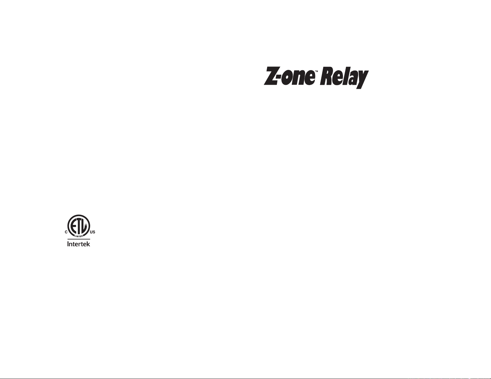
Wiring of 2 wire or 3 zone valve to Cale Z-one Relay
Wiring a 2 wire zone valve to Cale Z-one Relay
Since a two wire actuator does not have an end switch for feedback
to the relay box, the end switch terminals must have a jumper to
simulate the end swith. If the end switch jumper is not installed, no
demand will be sent to the boiler and the pumps will not turn on
STATUS
DURING
POWER IN
L
PRIORITY
ON OFF
PRIORITY
N
PUMP
L
SEC PUMP
N
L
SYSTEM
PUMP
N
L
N
MOTOR
PRIORITY
ON OFF
ZONE 1
SWITCH
END
ZONE 2
MOTOR
SWITCH
END
.
MOTOR
Wiring a 3 wire zone valve to Cale Z-one Relay
The Taco 570 zone valve presents a unique wiring challenge. When
connecting the Taco 570 zone valve to the Caleffi Z-one Relay, the
wiring of this valve can only be done in one way. The left motor
terminal on the ZVR series control must be connected to terminal
2 on the zone valve. The right motor terminal must be connected
to terminal 1 on the zone valve. Lastly, the left end switch terminal
must be connected to terminal 3 on the zone valve. Failure to
follow schematic will lead to damage of product.
TSAT5 ZONE5
TSAT6 ZONE6
ZONE 3
SWITCH
END
MOTOR
ZONE 4
SWITCH
END
ZONE 5
END
SWITCH
MOTOR
MOTOR
ZONE 6
SWITCH
END
M
1
2
3
5
Page 14
4009064
Certified to CSA C22-2 No.24
Conforms to UL Standard 873
6
ZSR101 - Single Zone Switching Relay
Overview
• Compatible with 2, 3 and 4-wire thermostats or other
low voltage controllers with switching action
• 120 VAC input
• Heavy duty, sealed, DPDT, fuse protected relay
(with spare fuse)
• Two dry contact outputs (Relay 1 and Relay 2) for
operating 120 VAC pump with boiler enable or two
devices without boiler enable
• 5 A capacity each relay - 10 A total
• Rear knock-outs for mounting onto 4”x4” junction box
• High capacity 6VA transformer
• Simplified wiring with pre-installed jumper
• 100% factory tested with 3 year warranty
• ETL certified
See technical brochure 01284-14 NA for more product
information.
Page 15
1 Zone
ZSR101
C
R
W
T T COM
L
POWER IN
N
C
RELAY #1
NO
NC
C
RELAY #2
NO
NC
TRANSFORMER
PWR
ZONE
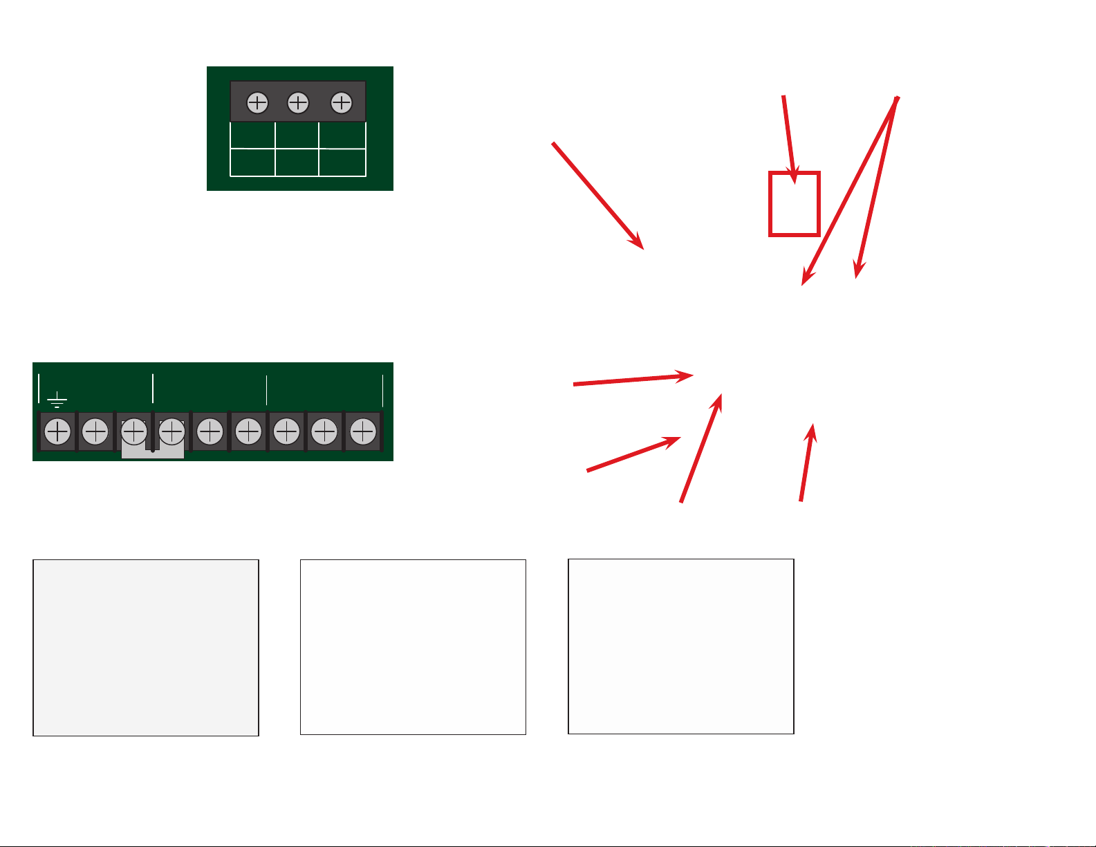
Operating Principles
When a zone has a
demand from a thermostat
(TT or R W) the relay will
close sending 120 VAC
to Relay #1 NO terminal
and switching the pump
on, and the C to NO dry
contact on relay #2 closes,
signaling the boiler of a heating demand.
R, W, C and T T Comm dual labeling at thermostat terminals.
Compatible with low voltage 2, 3, or 4 wire thermostats
other low voltage devices having a switching action.
Supply 120 VAC hot to terminal L and 120 VAC neutral to N.
A factory installed jumper from L terminal to the C terminal of
Relay 1 is supplied for simplified pump connection.
If dry contacts are desired from relay #1, remove the factory
installed jumper between L and C.
Cover removal
R
W
T T COM
C
or any
6 VA Transformer.
120VAC input
power connection
Keyhole mounting
which fits a 4X4
junction box.
Dual labeled T-stat terminals.
Compatible with 2, 3 and 4
wire T-stats.
Pre-installed jumper.
Replaceable fuses.
Rear knockout for
4X4 junction box.
Mounting: Do not mount to a
surface that exceeds 115°F (45°C).
The unit must be only located in dry
interior locations. Use only copper
conductor supply wire suitable for
at least 105° C. All circuits must
have a common disconnect and
be connected to the same pole of
the disconnect. It is not suitable for
installation in hazardous locations.
Hold either the left or the right end
of the box up and at an angle. Use
body for stabilizing relay box. Insert
screwdriver and push tab inward.
Turn box and repeat inserting
screwdriver and pushin tab inward on
opposite side, cover should release
from base.
Slide cover off base.
7
Page 16
A1 - Single thermostat
transformer
C
W
R
com
T
T
single zone relay
8
power
zone
Caleffi!
N LL
C N/O N/C C N/O N/C
N
L
Hydronic diagram is for illustration purposes only, some components have been removed for simplicity.
RELAY 1
RELAY 2
T
T
Page 17

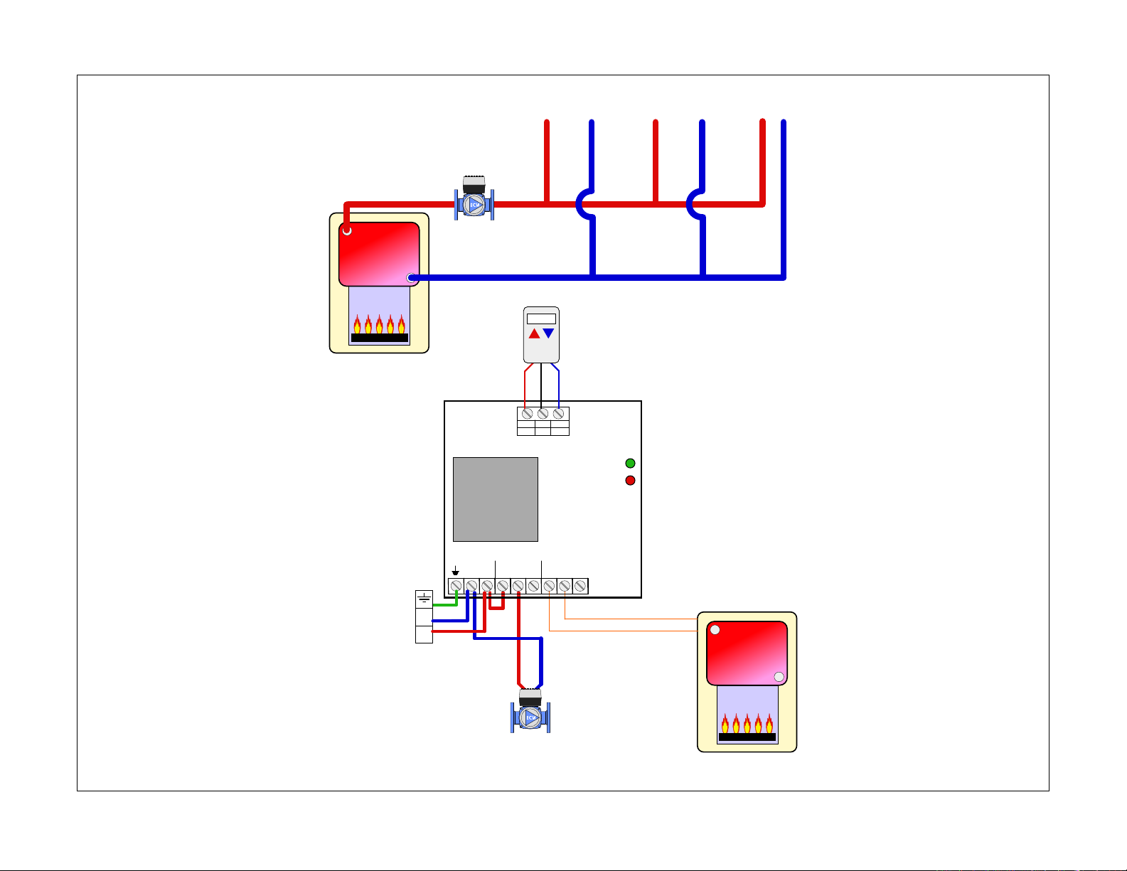
Description of terminals
Sequence of Operation / Settings
= Ground
N = Neutral (Common leg of 120 VAC)
L = Line (live leg of 120 VAC)
C = Common terminal
NO = Normally Open terminal
NC = Normally Closed terminal
Note: There is a factory installed jumper between the 120
VAC line (L) and the common terminal of relay #1 (C).
Thermostat terminals
R = 24 VAC
W = Heat call
C
= Common of 24 VAC
WARNING: NEVER CONNECT R & C DIRECTLY,
this will be a direct short on the 24 VAC supply
• A demand occurs and closes RW (TT)
• Relay #1 and relay #2 both fire connecting the
common terminal to the NO terminal.
• If the factory installed jumper has not been
removed, the NO terminal of relay #1 will
deliver the hot leg of 120 VAC. Relay #2 has
dry contacts.
• The zone LED illuminates.
• The demand is satisfied and opens RW (TT).
• The relay contacts return to their normal
position (common to normally closed).
• The zone LED turns off.
9
Page 18
A2 - Multiple thermostats
transformer
C
W
R
com
T
T
single zone relay
Caleffi!
power
zone
End switch wires
R W
R
W
4-wire zone valve
R
W
4-wire zone valve
10
4-wire zone valve
RELAY 1
C N/O N/C C N/O N/C
N LL
RELAY 2
N
L
Hydronic diagram is for illustration purposes only and could be missing system components.
24 VAC
T
T
Page 19
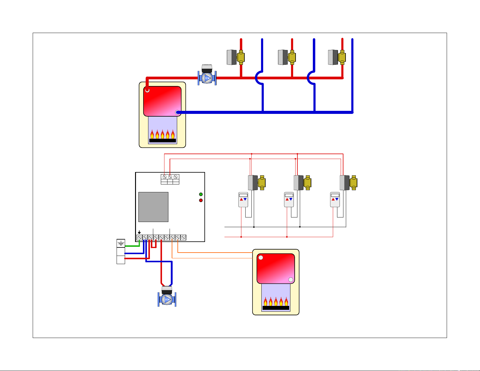
Description of terminals
Sequence of Operation / Settings
= Ground
N = Neutral (Common leg of 120 VAC)
L = Line (live leg of 120 VAC)
C = Common terminal
NO = Normally Open terminal
NC = Normally Closed terminal
Note: There is a factory installed jumper between the 120
VAC line (L) and the common terminal of relay #1 (C).
Thermostat terminals
R = 24 VAC
W = Heat call
C
= Common of 24 VAC
WARNING: NEVER CONNECT R & C DIRECTLY,
this will be a direct short on the 24 VAC supply
• There is a demand by one of the t-stats which
sends power to the corresponding zone valve.
• When the zone valve opens, its end switch
contacts close and signal a demand to the RW
(TT) contacts on the single zone relay control.
• Relay #1 and relay #2 fire
• If the factory installed jumper has not been
removed, the NO terminal of relay #1 will
deliver the hot leg of 120 VAC thus firing the
pump.
• Relay #2 closes the TT contacts on the boiler
signally a demand.
• The Zone LED illuminates.
• When the last of the T-stats is satisfied, the
corresponding zone valves closes which
opens the end switch contacts.
• The relay contacts return to their normal
position turning off power to the system pump
and opening the RW (TT) contacts.
• The Zone LED turns off.
11
Page 20
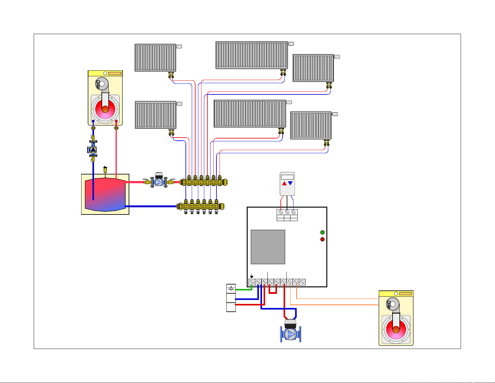
A3 - Single master thermostat, panel radiators with TRVs, variable speed pump
12
buffer tank
TRV
thermostatic!
radiator valves!
(TRV) on each!
radiator
TRV
TRV
TRV
TRV
TRV
C
W
R
com
T
T
Hydronic diagram is for illustration purposes only, some components have been removed for simplicity.
N
power
zone
transformer
Caleffi!
single zone relay
RELAY 1
C N/ON/C C N/ON/C
N LL
RELAY 2
T
L
T
Page 21
Description of terminals
= Ground
N = Neutral (Common leg of 120 VAC)
L = Line (live leg of 120 VAC)
C = Common terminal
NO = Normally Open terminal
NC = Normally Closed terminal
Note: There is a factory installed jumper between the 120
VAC line (L) and the common terminal of relay #1 (C).
Thermostat terminals
R = 24 VAC
W = Heat call
C
= Common of 24 VAC
WARNING: NEVER CONNECT R & C DIRECTLY,
this will be a direct short on the 24 VAC supply
Sequence of Operation / Settings
• A single “master” thermostat is wired to the
ZSR101 control. The master thermostat is set
to a slightly higher set point than the desired
room temperatures on the thermostatic
radiator valves.
• When the temperature drops below the
thermostat’s set point, a heat demand is
initiated by closing the R & W terminals.
• Relay #1 and relay #2 both fire.
• If the factory installed jumper has not been
removed, the NO terminal of relay #1 will
deliver 120 VAC line to the variable speed
circulator.
• Relay #2 closes the TT contacts on the boiler
signaling a demand.
• The Zone LED illuminates.
• Using an outside air sensor and system
temperature sensor located in the buffer tank,
the boiler determines if the water in the boiler
meets the target temperature based off the
outside air reset curve.
• The relay contacts return to their normal
position turning off power to the variable
speed circulator and opening the RW (TT)
contacts. Both the boiler and pump are
no longer enabled.
• The Zone LED turns off.
• As long as the master thermostat is calling,
the boiler will maintain the buffer tank to the
target temperature.
• The thermostatic radiator valves modulate the
flow through the panel radiators because the
variable speed circulator is enabled.
• When the master thermostat reaches set
point, the master thermostat will open the
contact between R & W.
13
Page 22
4009064
Certified to CSA C22-2 No.24
Conforms to UL Standard 873
14
ZSR10X - Multi-Zone Pump Control
Overview
• Compatible with low voltage 2, 3, or 4 wire
thermostats
• R, W, C and TT Comm dual labeling at thermostat
terminals
• Z-oneLink unlimited zone expansion
• 120 VAC pump outputs
• Selectable priority with 1 hour time-out feature
• Selectable post purge and exercise
• Dry contacts for DHW (ZR/ZC), capable of switching
line voltage
• High capacity transformer
• Large terminal connections
• Simplified wiring with extra ground terminals
• Heavy duty sealed relays
• Fuse protected (with spare fuse)
• Front LED lights
• 100% Factory tested with 3 year warranty
• ETL approved
See technical brochure 01286-14 NA for more product
information.
Page 23
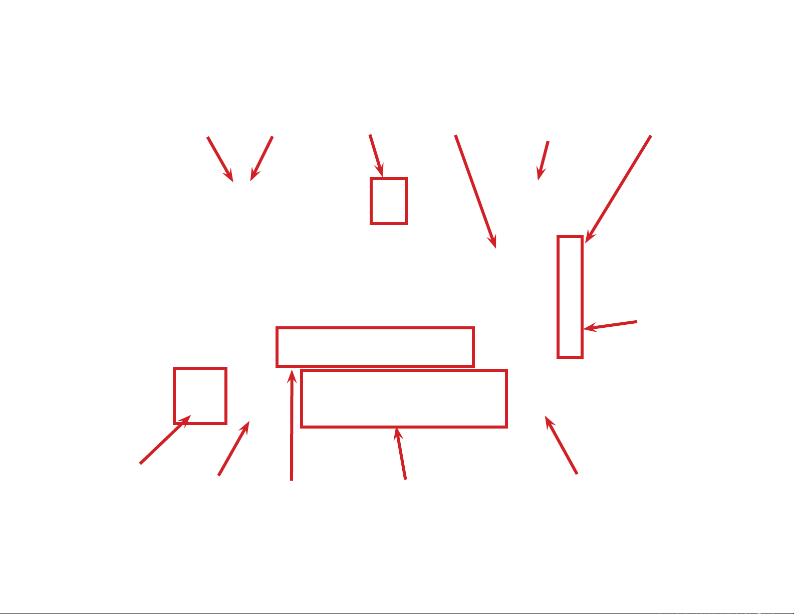
XX Closes for
heat demand
and DHW
demand. Rated
for 120 VAC,
2 amps.
DHW (ZR/ZC)
closes only
during priority
call. Rated
for 120 VAC,
2 amps.
Dual labeled
T-stat terminals.
Compatible with
2, 3 and 4 wire
T-stats.
Selectable DIP
switches.
3 wire
communications to
expansion board.
Power ON LED.
LED for each
zone.
120 VAC input
power connection
Multiple ground
connections for
easy wiring.
Replaceable
fuses (2 extra
included under
cover).
120 VAC zone
pump outputs.
120 VAC primary
pump output.
15
Page 24

Cover removal
16
Hold either the left or the right end
of the box up and at an angle. Use
body for stabilizing relay box.
Mounting: Do not mount to a surface that exceeds 115°F (45°C). The unit must
be only located in dry interior locations. Use only copper conductor supply wire
suitable for at least 105° C. All circuits must have a common disconnect and be
connected to the same pole of the disconnect. It is not suitable for installation
in hazardous locations.
Insert screwdriver and push tab
inward, cover should release from
base.
Roll cover off base.
Page 25
T-STAT 2
C
R
W
T T COM
COMMS
D
P
DHW
ZR/ZC
X X
T-STAT 3
C
R
W
T T COM
T-STAT 1
C
R
W
T T COM
T-STAT 4
C
R
W
T T COM
T-STAT 5
C
R
W
T T COM
T-STAT 6
C
R
W
T T COM
PWR
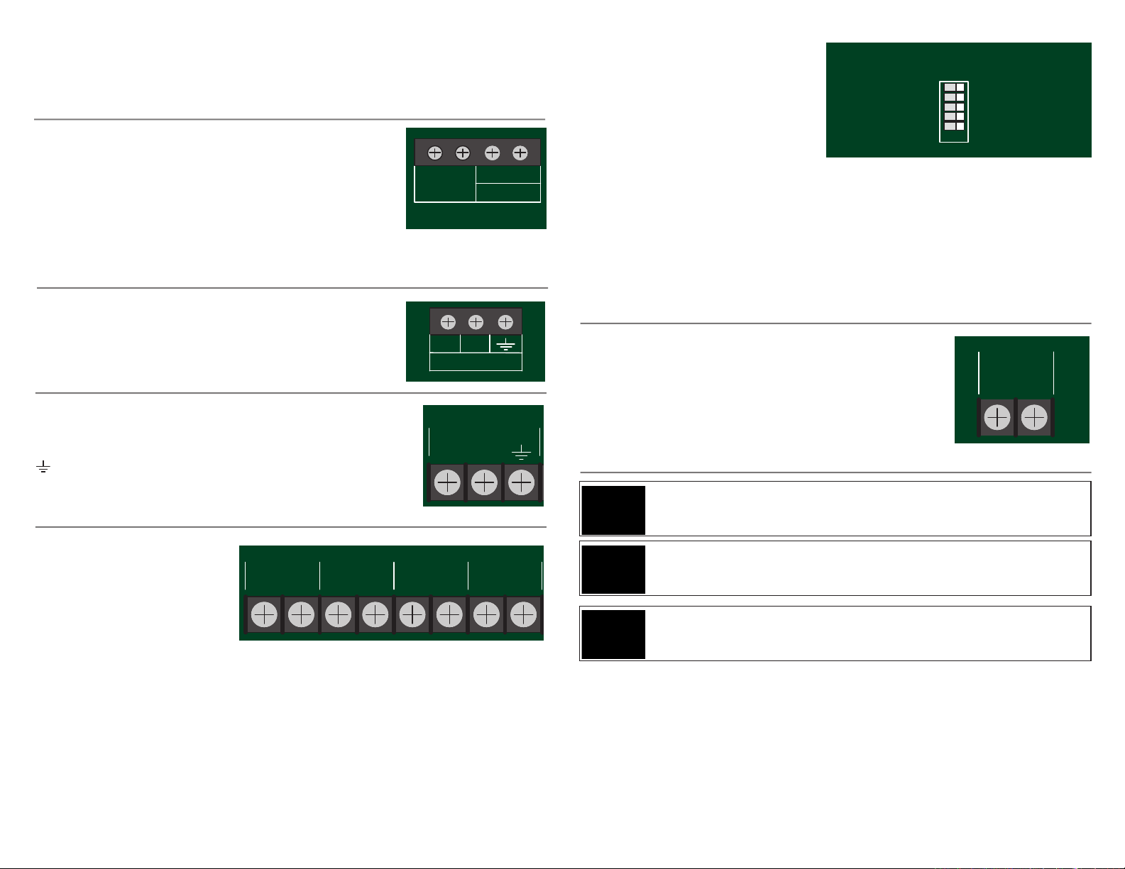
Maintenance and Repair: The Caleffi Z-one™ multi-zone pump control
COMMS
D
P
PWR
6 Zone
T-STAT 2
C
R
W
T T COM
COMMS
D
P
DHW
ZR/ZC
X X
T-STAT 3
C
R
W
T T COM
T-STAT 1
C
R
W
T T COM
L
PUMP 2
N
PRIMARY
PUMP
L
PRIORITY
PUMP 1
N
L
POWER IN
N
GROUNDS
L
PUMP 3
N
TRANSFORMER
L
N
T-STAT 4
C
R
W
T T COM
L
PUMP 4
N
L
PUMP 5
N
L
PUMP 6
N
T-STAT 5
C
R
W
T T COM
T-STAT 6
C
R
W
T T COM
PWR
ZONE1
ZONE2
ZONE3
ZONE4
ZONE5
ZONE6
DipSwitches
Master Slave
Priority OFF
Priority ON
Primary OFF
Primary ON
Exercise OFF
Exercise ON
Post Purge OFF
Post Purge ON
ZSR106
6 Zone
T-STAT 2
C
R
W
T T COM
COMMS
D
P
T-STAT 3
C
R
W
T T COM
L
PUMP 2
N
PRIMARY
PUMP
L
PRIORITY
PUMP 1
N
L
PUMP 3
N
L
N
T-STAT 4
C
R
W
T T COM
L
PUMP 4
N
L
PUMP 5
N
L
PUMP 6
N
T-STAT 5
C
R
W
T T COM
T-STAT 6
C
R
W
T T COM
PWR
ZONE1
ZONE2
ZONE3
ZONE4
ZONE5
ZONE6
DipSwitches
Master Slave
Priority OFF
Priority ON
Primary OFF
Primary ON
Exercise OFF
Exercise ON
Post Purge OFF
Post Purge ON
ZSR106
COMMS
D
P
PRIMARY
PUMP
L
N
C
PWR
ZONE1
ZONE2
ZONE3
ZONE4
ZONE5
ZONE6
COMMS
D
P
C
W
T-STAT 5
C
R
W
T T COM
T-STAT 6
C
R
W
T T COM
PWR
ZONE1
ZONE2
ZONE3
ZONE4
comes with two spare fuses. If control fails or is damaged, replace control with
functional one.
Boiler connections:
XX = Dry contacts rated up to 120 VAC, 2 Amps.
Closes when any zone calls including priority. Typically
connected to TT on boiler control.
DHW (ZR/ZC) = Dry contacts rated up to 120 VAC, 2
Amps. Closes only when priority is enabled and calling.
Typically used to close ZR\ZC (120 VAC) or DHW contacts (24 VAC) on boiler
controls equipped with these features.
Communication connections:
Connect terminals to matching terminal of slave boards
D to D, P to P, Ground to Ground
Input Power:
L = Line (hot leg) of 120 VAC supply
N = Neutral of 120 VAC
= Ground
Note: when connecting 2 or more Z-one controls, all
controls must be powered by the same 120 VAC circuit.
Zone pump outputs:
Zone pumps run when
corresponding thermostat
initiates a demand.
GROUND = Connect the
ground from the pump to the
ground terminal.
PRIORITY PUMP = Runs when zone #1 calls. Can be programmed to be the
priority zone.
L = Line (hot leg) of 120 VAC to power the pump
N = Neutral leg of 120 VAC to power the pump
The DIP Switches on the ZSR series
can be positioned for the following
operations.
Master / Slave: allows for unlimited
expansion to additional ZSR relays.
DipSwitches
Master Slave
Priority OFF
Primary OFF
Exercise OFF
Post Purge OFF
Priority ON
Primary ON
Exercise ON
Post Purge ON
Priority OFF / Priority ON: When
priority mode is ON, upon demand,
zone 1 will operate as priority and all other zones are temporarily switched off
(with 1 hour time-out). When priority mode is OFF, all zones remain active.
Primary OFF / Primary ON: When primary mode is ON, the primary pump will
continue to operate during priority.
Exercise OFF / Exercise ON: When exercise mode is ON, each circulator is
switched on for 30 seconds following 72 hours of inactivity.
Post Purge OFF / Post Purge ON: When post purge is ON, the priority pump
continues operating for 2 minutes after the priority zone is switched off.
Primary pump output:
Primary pump runs when any zone pump runs. Its status
during priority (on\off) can be programmed using the DIP
switches.
L = Line (hot leg) of 120 VAC to power the pump
N = Neutral leg of 120 VAC to power the pump
WARNING: NEVER CONNECT R & C DIRECTLY, this will be a direct short on the 24 VAC
supply.
WARNING: When connecting 2 or more Z-one controls, all controls must be powered by
the same 120 VAC circuit.
WARNING: When replacing fuses, make sure power is disconnected to control box.
17
Page 26
6 Zone
T-STAT 2
CRW
T T COM
COMMS
D
P
DHW
ZR/ZC
X X
T-STAT 3
CRW
T T COM
T-STAT 1
CRW
T T COM
L
PUMP 2
N
PRIMARY
PUMP
L
PRIORITY
PUMP 1
N
L
POWER IN
N
GROUNDS
L
PUMP 3
N
TRANSFORMER
L
N
T-STAT 4
CRW
T T COM
L
PUMP 4
N
L
PUMP 5
N
L
PUMP 6
N
T-STAT 5
CRW
T T COM
T-STAT 6
CRW
T T COM
PWR
ZONE1
ZONE2
ZONE3
ZONE4
ZONE5
ZONE6
DipSwitches
Master Slave
PriorityOFF
PriorityON
PrimaryOFF
PrimaryON
ExerciseOFF
ExerciseON
PostPurge OFF
PostPurge ON
ZSR106
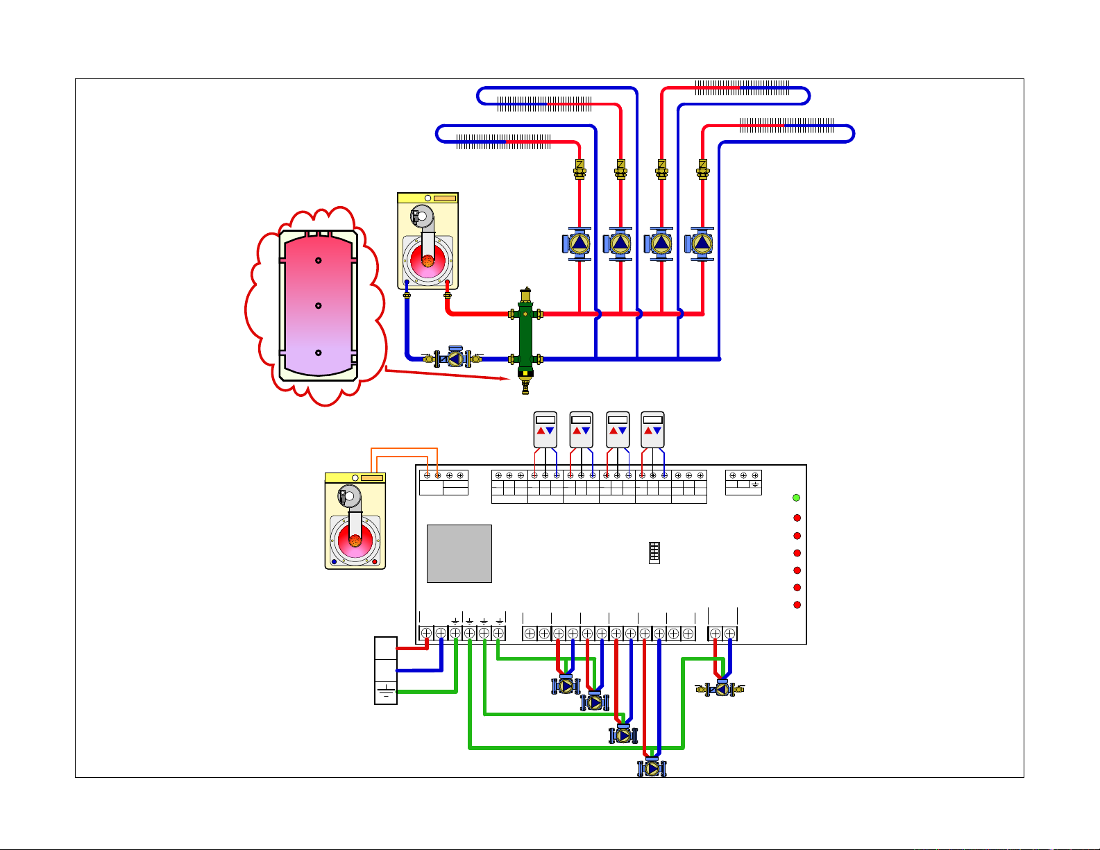
B1 - Mod/con boiler, hydro separator or buffer tank, zone pumps
Pump 2
Pump 1
Buffer tank- Optional hydraulic
separator
Pump 3
18
Pump 4
N
L
Hydronic diagram is for illustration purposes only, some components have been removed for simplicity.
Page 27
Description of terminals
Sequence of Operation / Settings
= Ground
N = Neutral (Common leg of 120 VAC)
L = Line (Hot leg of 120 VAC)
Thermostat terminals
R = 24 VAC
W = Heat call
C
= Common of 24 VAC
Boiler terminals
XX = Dry contacts rated up to 120 VAC, 2 Amps.
Closes when any zone calls including priority.
Typically connected to TT on boiler control.
DHW (ZR/ZC) = Dry contacts rated up to 120 VAC,
2 Amps. Closes only when priority is enabled and
calling. Typically used to close ZR\ZC (120 VAC)
or DHW contacts (24 VAC) on boiler controls
equipped with these features.
Dip switch description
Master / Slave: Used when joining 2 or more
controls together. Only one Master per group
Priority OFF / Priority ON: Used to set Zone #1
as the priority zone. All other zones will hold off
during priority. Priority has a one hour time out
feature to prevent freeze up.
Primary OFF / Primary ON: Sets the status of the
primary pump when there is a priority call. This
allows the DHW pump to be on either side of a
hydro separator.
Exercise OFF / Exercise ON: When enabled the
pumps will rub for 30 seconds after 72 hours
without a demand.
Post Purge OFF / Post Purge ON: Allows the DHW
pump to run for 2 minutes after the DHW demand
has been satisfied.
Priority switch: OFF
Master / Slave switch: Master
Status During Priority switch: OFF
• A demand occurs from any T-stat (T-stat
closes TT terminals). The “PUMP ON” LED
illuminates for that zone.
• ZSR control sends 120 VAC to the
corresponding zone pump and the primary
pump outputs, XX contacts close to signal
boiler of a demand.
• When the demand from the last T-stat calling
is satisfied (T-stat opens TT terminals), the XX
contacts are opened, the “PUMP ON” LED
turns off and the 120 VAC to the zone pump
and primary pump outputs are dropped.
WARNING: NEVER CONNECT R & C DIRECTLY,
this will be a direct short on the 24 VAC supply
19
Page 28
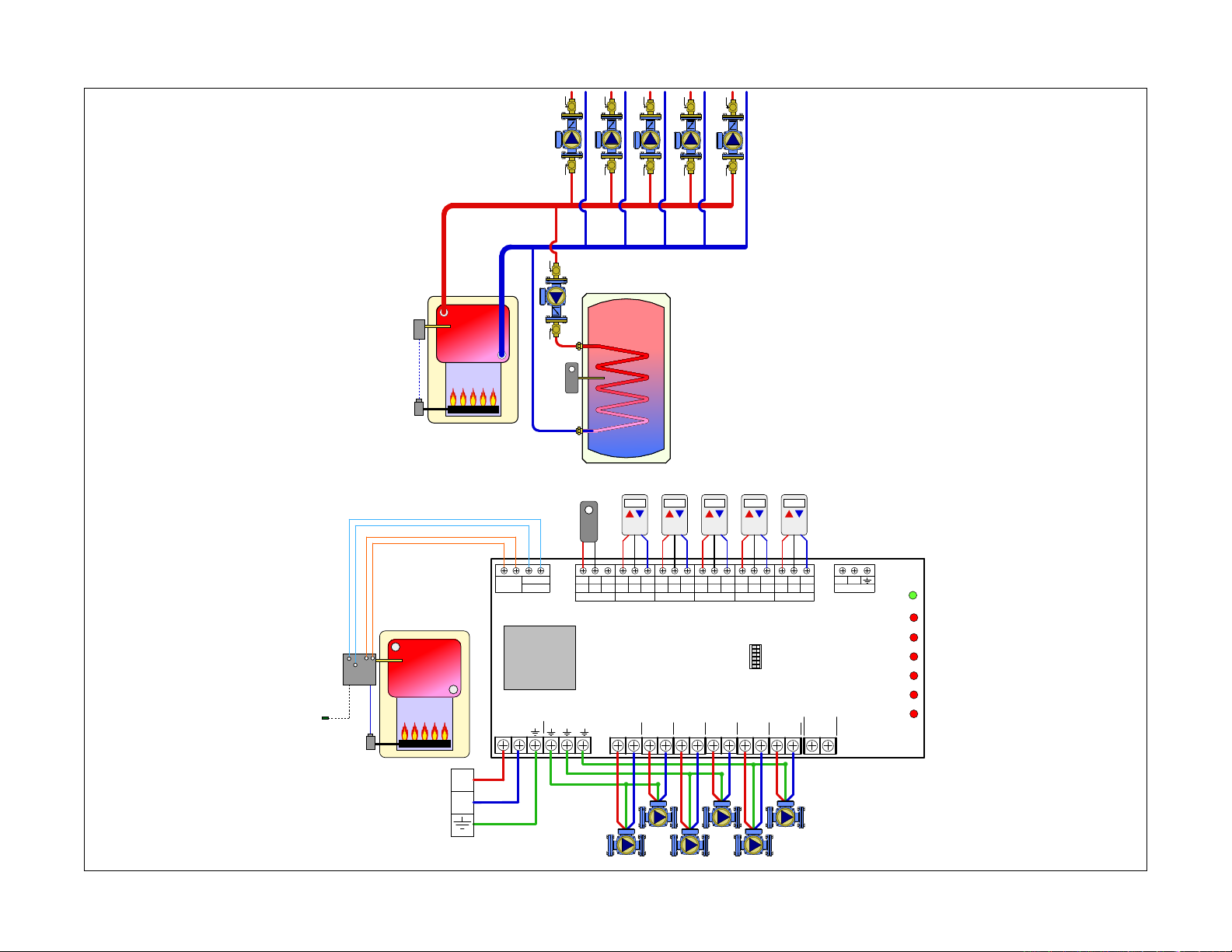
B2 - Traditional boiler, indirect DHW w/ priority, zone pumps
Pump 3
Pump 4
Pump 5
boiler!
high limit!
control
Pump 1
DHW!
aquastat
Pump 2
DHW!
aquastat
20
Pump 6
DHW
X X
ZR/ZC
TRANSFORMER
outdoor!
temperature!
sensor
T T
ZC
ZR
POWER IN
L
12/20VA
N
L
N
Hydronic diagram is for illustration purposes only, some components have been removed for simplicity.
GROUNDS
T T COM
THM 1
CRW
T T COM
THM 2
PRIORITY
PUMP 1
L
CRW
PUMP 2
L
N
CRW
T T COM
THM 3
6 Zone
Z6P
ZSR106
PUMP 3
L
N
T T COM
THM 4
N
PUMP 4
L
CRW
Priority OFF
Primary OFF
Exercise OFF
Post Purge OFF
N
T T COM
THM 5
DipSwitches
Master Slave
Priority ON
Primary ON
Exercise ON
Post Purge ON
PUMP 5
N
L
CRW
T T COM
THM 6
PUMP 6
N
L
CRW
PRIMARY
PUMP
L
D
P
COMMS
N
PWR
ZONE1
ZONE2
ZONE3
ZONE4
ZONE5
ZONE6
Page 29
Description of terminals
Sequence of Operation / Settings
= Ground
N = Neutral (Common leg of 120 VAC)
L = Line (Hot leg of 120 VAC)
Thermostat terminals
R = 24 VAC
W = Heat call
C
= Common of 24 VAC
Boiler terminals
XX = Dry contacts rated up to 120 VAC, 2 Amps.
Closes when any zone calls including priority.
Typically connected to TT on boiler control.
DHW (ZR/ZC) = Dry contacts rated up to 120 VAC,
2 Amps. Closes only when priority is enabled and
calling. Typically used to close ZR\ZC (120 VAC)
or DHW contacts (24 VAC) on boiler controls
equipped with these features.
Dip switch description
Master / Slave: Used when joining 2 or more
controls together. Only one Master per group
Priority OFF / Priority ON: Used to set Zone #1
as the priority zone. All other zones will hold off
during priority. Priority has a one hour time out
feature to prevent freeze up.
Primary OFF / Primary ON: Sets the status of the
primary pump when there is a priority call. This
allows the DHW pump to be on either side of a
hydro separator.
Exercise OFF / Exercise ON: When enabled the
pumps will rub for 30 seconds after 72 hours
without a demand.
Post Purge OFF / Post Purge ON: Allows the DHW
pump to run for 2 minutes after the DHW demand
has been satisfied.
Priority switch: ON (Zone #1 becomes priority)
Master/Slave switch: Master
Primary Status During Priority switch: OFF
• A demand occurs from a T-stat (T-stat closes
TT terminals) in zones 2 thru 6.
• The “PUMP ON” LED illuminates for that zone.
• ZSR control sends 120 VAC to the
corresponding zone pump terminals to fire
the zone pump and closes the XX contacts
to signal a heat demand to the boiler. The
PRIMARY PUMP output will also deliver 120
VAC even if no pump is connected.
• When the demand from the T-stat is satisfied
(T-stat opens TT terminals), the “PUMP ON”
LED turns off.
• 120 VAC is dropped from the corresponding
zone pump terminals.
• If no other zones are calling, power is dropped
to the SEC PUMP and SYSTEM PUMP and
the XX contacts are opened.
• If a demand occurs from the DHW aquastat
(zone #1), The “PUMP ON” LED illuminates for
Zone #1.
• If any other zone was calling (Zones 2 thru
6) when Zone #1 called, power (120 VAC) is
dropped to those zone pumps.
• The XX and DHW contacts close.
• The PRIORITY PUMP contacts deliver 120
VAC
• Once the Zone #1 DHW demand is satisfied,
power to the PRIORITY PUMP is dropped, the
DHW contacts open.
• If a demand from zones 2 thru 6 is present,
120 VAC is delivered to the corresponding
zone pump(s) and the “PUMP ON” LED for
those zones will illuminate.
• The XX contacts close to signal a heat demand
to the boiler.
• When all zones are satisfied, the XX contacts
open and power (120 VAC) is turned off to all
of the zone pumps.
DHW Time Out \ Freeze Prevention Feature
• After one hour of a priority demand, the control
will open the DHW contacts and turn off power
to the DHW pump.
• If a heating demand is present from Zones
#2- 6, the control will satisfy those demands
before going back to the DHW call.
• After the heating demands are met, the control
will go back to DHW and re-set the one hour
timer.
WARNING: NEVER CONNECT R & C DIRECTLY,
this will be a direct short on the 24 VAC supply
21
Page 30
6 Zone
T-STAT 2
CRW
T T COM
COMMS
D
P
DHW
ZR/ZC
X X
T-STAT 3
CRW
T T COM
T-STAT 1
CRW
T T COM
L
PUMP 2
N
PRIMARY
PUMP
L
PRIORITY
PUMP 1
N
L
POWER IN
N
GROUNDS
L
PUMP 3
N
TRANSFORMER
L
N
T-STAT 4
CRW
T T COM
L
PUMP 4
N
L
PUMP 5
N
L
PUMP 6
N
T-STAT 5
CRW
T T COM
T-STAT 6
CRW
T T COM
PWR
ZONE1
ZONE2
ZONE3
ZONE4
ZONE5
ZONE6
DipSwitches
Master Slave
Priority OFF
Priority ON
Primary OFF
Primary ON
Exercise OFF
Exercise ON
Post Purge OFF
Post Purge ON
ZSR106
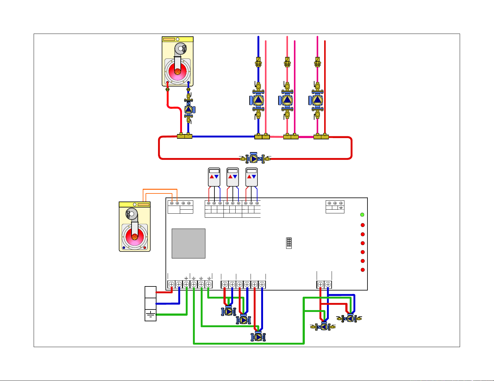
B3 - Mod/Con boiler, primary loop, closely spaced tees, zone pumps
22
boiler pump
Pump 1
Primary pump
3
3
Pump 2
Pump 3
L
N
Hydronic diagram is for illustration purposes only, some components have been removed for simplicity.
boiler pump
Primary pump
Page 31
Description of terminals
Sequence of Operation / Settings
= Ground
N = Neutral (Common leg of 120 VAC)
L = Line (Hot leg of 120 VAC)
Thermostat terminals
R = 24 VAC
W = Heat call
C
= Common of 24 VAC
Boiler terminals
XX = Dry contacts rated up to 120 VAC, 2 Amps.
Closes when any zone calls including priority.
Typically connected to TT on boiler control.
DHW (ZR/ZC) = Dry contacts rated up to 120 VAC,
2 Amps. Closes only when priority is enabled and
calling. Typically used to close ZR\ZC (120 VAC)
or DHW contacts (24 VAC) on boiler controls
equipped with these features.
Dip switch description
Master / Slave: Used when joining 2 or more
controls together. Only one Master per group
Priority OFF / Priority ON: Used to set Zone #1
as the priority zone. All other zones will hold off
during priority. Priority has a one hour time out
feature to prevent freeze up.
Primary OFF / Primary ON: Sets the status of the
primary pump when there is a priority call. This
allows the DHW pump to be on either side of a
hydro separator.
Exercise OFF / Exercise ON: When enabled the
pumps will rub for 30 seconds after 72 hours
without a demand.
Post Purge OFF / Post Purge ON: Allows the DHW
pump to run for 2 minutes after the DHW demand
has been satisfied.
Priority switch OFF
Master / Slave switch: Master
Status During Priority switch: OFF
• A demand occurs from any T-stat (T-stat
closes TT terminals). The “PUMP ON” LED
illuminates for that zone.
• ZSR control sends 120 VAC to the
corresponding zone pump and the primary
pump outputs, XX contacts close to signal
boiler of a demand.
• When the demand from the T-stat is satisfied
(T-stat opens TT terminals), the XX contacts
are opened, the “PUMP ON” LED turns off and
the 120 VAC to the zone pump and primary
pump outputs are turned off.
• ALTERNATE WIRING: The boiler pump can be
controlled by the Mod/Con boiler if equiped to
do so.
WARNING: NEVER CONNECT R & C DIRECTLY,
this will be a direct short on the 24 VAC supply
23
Page 32
4009064
Certified to CSA C22-2 No.24
Conforms to UL Standard 873
24
ZVR10X - Multi-Zone Valve Control
Overview
• Compatible with low voltage 2, 3, or 4 wire thermostats
• R, W, C and TT Comm dual labeling at thermostat
terminals
• Z-oneLink unlimited zone expansion
• Selectable priority with 1 hour time-out feature
• System pump status selectable during priority
• Pump will start only after the zone valve end switch
is closed
• Dry contacts for DHW (ZR/ZC), capable of switching
line voltage
• Large terminal connections
• High capacity 40 VA transformer standard for 3 and
4 zone models-expandable to 80 VA, and 80 VA for
the 6 zone model
• Automatic resettable fuse
• Controls system pump, secondary pump, and priority
pump
• Front LED Lights
• 100% Factory tested with 3 year warranty
• ETL approved
See technical brochure 01285-14 NA for more product
information.
Page 33
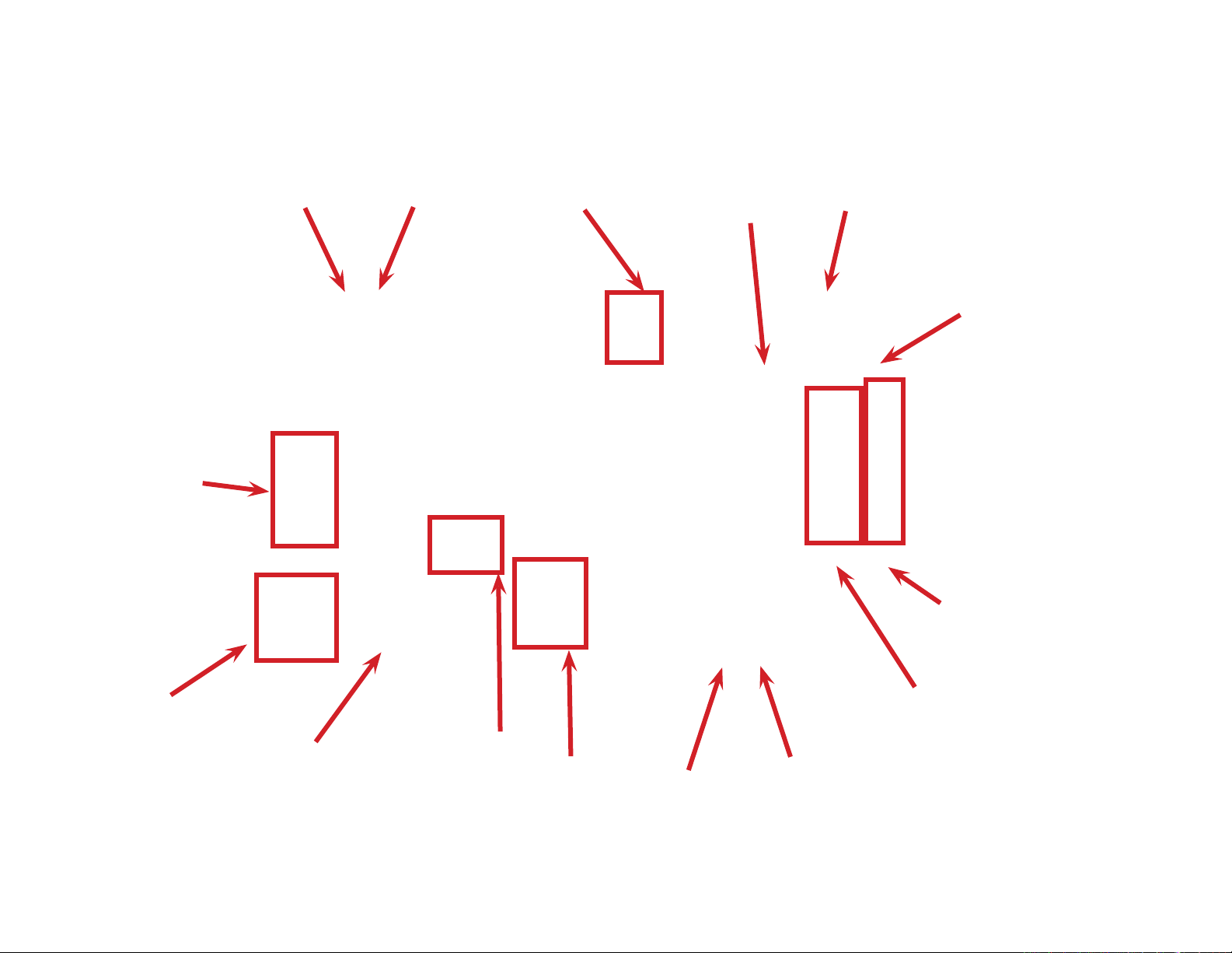
Transformer
connections.
XX Closes for
heat demand
and DHW
demand. Rated
for 120 VAC
2 amps.
DHW (ZR/ZC)
closes only
during priority
call. Rated
for 120 VAC,
2 amps.
Dual labeled
T-stat terminals.
Compatible with
2, 3 and 4 wire
T-stats.
Master/Slave
jumper.
3 wire
communications
to expansion
board.
Power ON LED.
120 VAC input
power connection.
120 VAC output
to pumps.
System pump
(boiler pump)
status during
priority can be
changed with
jumper.
ZONE #1
priority.
Zone valve motor
connections.
LED illuminates
when end switch
closes.
LED illuminates
with call for
heat.
Zone valve
end switch
connection.
25
Page 34

Cover removal
26
Hold either the left or the right end
of the box up and at an angle. Use
body for stabilizing relay box.
Transformer Installation
Mount box on stable surface using
level.
Insert screwdriver and push tab
inward, cover should release from
base.
Remove transformer(s) from
packaging.
Roll cover off base.
Slide bottom end of transformer
into bottom latch.
Mounting: Do not mount to a surface that exceeds 115°F (45°C). The unit must
be only located in dry interior locations. Use only copper conductor supply wire
suitable for at least 105° C. All circuits must have a common disconnect and be
connected to the same pole of the disconnect. It is not suitable for installation
in hazardous locations.
Snap top of transformer into latch
arms.
Feed wiring through hole near the
top of the transformer and insert
transformer plug into the socket.
Repeat process for 2nd
transformer if using six valve relay
box.
Page 35
COMMS
D
P
T-STAT 3
C
COM
T-STAT 4
C
R
W
T T COM
T-STAT 5
C
R
W
T T COM
T-STAT 6
C
R
W
T T COM
PWR
ZONE1
6 Zone
ZVR106
PWR
TSAT1 ZONE1
TSAT2 ZONE2
TSAT3 ZONE3
TSAT4 ZONE4
TSAT5 ZONE5
TSAT6 ZONE6
MASTER SLAVE
C
W
COMMS
D
P
T-STAT 3
C
R
W
T T COM
T-STAT 4
C
R
W
T T COM
T-STAT 5
C
R
W
T T COM
T-STAT 6
C
R
W
T T COM
6 Zone
ZVR106
PWR
TSAT1 ZONE1
TSAT2 ZONE2
TSAT3 ZONE3
TSAT4 ZONE4
TSAT5 ZONE5
TSAT6 ZONE6
PRIORITY
ON OFF
MASTER SLAVE
T-STAT 2
C
R
W
T T COM
COMMS
D
P
T-STAT 3
C
R
W
T T COM
T-STAT 1
C
W
T-STAT 4
C
R
W
T T COM
T-STAT 5
C
R
W
T T COM
T-STAT 6
C
R
W
T T COM
PWR
TSAT1 ZONE1
COMMS
D
P
T-STAT 6
C
R
W
T T COM
Maintenance and Repair: The Caleffi Z-one™ multi-zone valve relay comes with
R
6 Zone
T-STAT 2
C
R
W
T T COM
COMMS
D
P
DHW
ZR/ZC
X X
T-STAT 3
C
R
W
T T COM
T-STAT 1
C
R
W
T T COM
L
PUMP 2
N
PRIMARY
PUMP
L
PRIORITY
PUMP 1
N
L
PUMP 3
N
TRANSFORMER
L
N
T-STAT 4
C
R
W
T T COM
L
PUMP 4
N
L
PUMP 5
N
L
PUMP 6
N
T-STAT 5
C
R
W
T T COM
T-STAT 6
C
R
W
T T COM
PWR
ZONE1
ZONE2
ZONE3
ZONE4
ZONE5
ZONE6
DipSwitches
Master Slave
Priority OFF
Priority ON
Primary OFF
Primary ON
Exercise OFF
Exercise ON
Post Purge OFF
Post Purge ON
ZSR106
6 Zone
ZVR106
PWR
TSAT1 ZONE1
TSAT2 ZONE2
TSAT3 ZONE3
TSAT4 ZONE4
TSAT5 ZONE5
TSAT6 ZONE6
L
PRIORITY
PUMP
N
L
SEC PUMP
N
STATUS
DURING
PRIORITY
ZONE 1
END
SWITCH
MOTOR
PRIORITY
ZONE 2
END
SWITCH
MOTOR
ZONE 3
END
SWITCH
MOTOR
ZONE 4
END
SWITCH
MOTOR
ZONE 5
END
SWITCH
MOTOR
ZONE 6
END
SWITCH
MOTOR
ON OFF
ON OFF
L
SYSTEM
PUMP
N
MASTER SLAVE
T-STAT 2
C
R
W
T T COM
COMMS
D
P
T-STAT 3
C
R
W
T T COM
T-STAT 1
C
R
W
T T COM
T-STAT 4
C
R
W
T T COM
T-STAT 5
C
R
W
T T COM
T-STAT 6
C
R
W
T T COM
6 Zone
ZVR106
PWR
TSAT1 ZONE1
TSAT2 ZONE2
TSAT3 ZONE3
TSAT4 ZONE4
TSAT5 ZONE5
TSAT6 ZONE6
ZONE 1
END
SWITCH
MOTOR
PRIORITY
ZONE 2
END
SWITCH
MOTOR
ZONE 3
END
SWITCH
MOTOR
ZONE 4
END
SWITCH
MOTOR
ZONE 5
END
SWITCH
MOTOR
ZONE 6
END
SWITCH
MOTOR
ON OFF
MASTER SLAVE
C
COMMS
D
P
T-STAT 3
C
R
W
T T COM
T-STAT 4
C
R
W
T T COM
T-STAT 5
C
R
W
T T COM
T-STAT 6
C
R
W
T T COM
a resettable fuse and requires no maintenance. If control fails or is damaged,
replace control with functional one.
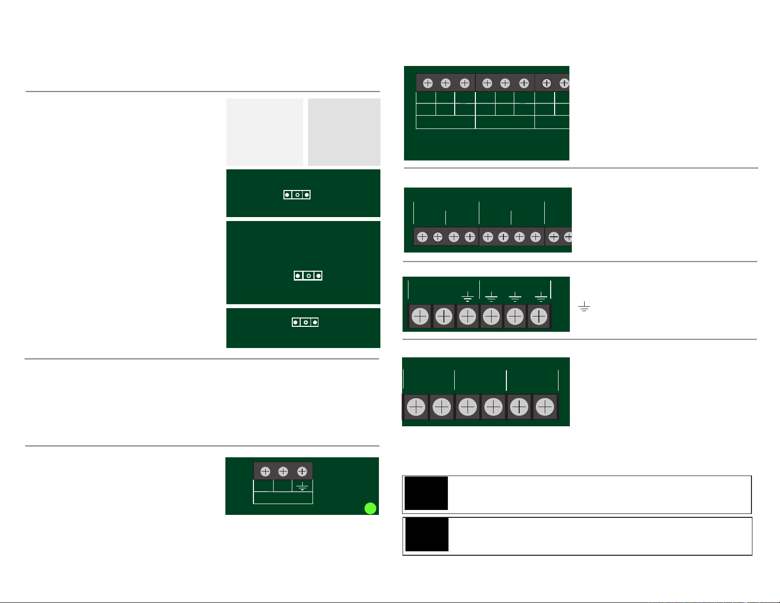
The ZVR series of controls is programmed
by positioning a series of jumpers. Example
photo to right shows jumper in off position
(left photo) and on position (right photo).
Jumpers are used for the following
operations.
Priority ON / Priority OFF: When priority
PRIORITY
jumper is ON, upon demand, zone 1 will
operate as priority and all other zones are
ON OFF
temporarily switched off (with 1 hour timeout). When priority mode is OFF, any zones
that were active when zone 1 was switched
on will remain on.
Status During Priority ON / Status During
Priority OFF: When status jumper is ON,
STATUS
DURING
PRIORITY
ON OFF
the system pump will continue to operate
during priority.
Master / Slave: allows for unlimited expansion
to additional ZVR relays.
Boiler Connections
XX = Dry contacts rated up to 120 VAC, 2 Amps. Closes when any zone calls
MASTER SLAVE
including priority. Typically connected to TT on boiler control.
DHW (ZR/ZC) = Dry contacts rated up to 120 VAC, 2 Amps. Closes only
when priority is enabled and calling. Typically used to close ZR\ZC (120 VAC)
or DHW contacts (24 VAC) on boiler controls equipped with these features.
Communication connections
Connect terminals to matching terminal of
slave boards
D to D, P to P, Ground to Ground
Use 18 gauge thermostat wire. Wire
should be shielded if located in close proximity to high voltage wiring.
D
COMMS
P
PW
Thermostat connections
R = 24 VAC.
W = Heat call
C = Common of 24 VAC
R
T T COM
C
W
T-STAT 1
R
W
T T COM
T-STAT 2
R
T T
W
Heat demand is initiated by closing R
to W.
C
24 VAC is always present between R
& C.
Zone valve connections
Motor = 24 VAC to power the zone
valve motor
End Switch = Connects to end switch
on zone valve. Must be jumpered if
using a 2 –wire zone valve.
Input power
POWER IN
L
GROUNDS
N
L = Line (hot leg) of 120 VAC supply
N = Neutral of 120 VAC
= Ground
Pump outputs
calls for heat except the priority zone when it is enabled.
PRIORITY PUMP = Runs when the priority zone calls. A jumper is required
between the END SWITCH terminals when using a pump for DHW.
SYSTEM PUMP = Runs when any
zone calls for heat. When priority is
enabled, the status of the pump (on\
off) during a priority call is selected via
a jumper
SEC PUMP = Runs when any zone
WARNING: NEVER CONNECT R & C DIRECTLY, this will be a direct short on the 24
VAC supply.
WARNING: When connecting 2 or more Z-one controls, all controls must be powered
by the same 120 VAC circuit.
27
Page 36
6 Zone
ZVR106
T-STAT 2
CRW
T T COM
COMMS
D
P
DHW
ZR/ZC
X X
T-STAT 3
CRW
T T COM
T-STAT 1
CRW
T T COM
L
POWER IN
N
T-STAT 4
CRW
T T COM
T-STAT 5
CRW
T T COM
T-STAT 6
CRW
T T COM
PWR
TSAT1 ZONE1
TSAT2 ZONE2
TSAT3 ZONE3
TSAT4 ZONE4
TSAT5 ZONE5
TSAT6 ZONE6
L
PRIORITY
PUMP
N
L
SEC PUMP
N
STATUS
DURING
PRIORITY
ZONE 1
END
SWITCH
MOTOR
PRIORITY
ZONE 2
END
SWITCH
MOTOR
ZONE 3
END
SWITCH
MOTOR
ZONE 4
END
SWITCH
MOTOR
ZONE 5
END
SWITCH
MOTOR
ZONE 6
END
SWITCH
MOTOR
ON OFF
ON OFF
L
SYSTEM
PUMP
N
MASTER SLAVE
L
N
PRIORITY!
pump
SECONDARY!
pump
ZV1
ZV4ZV3ZV2 ZV5 ZV6
mod/con!
boiler
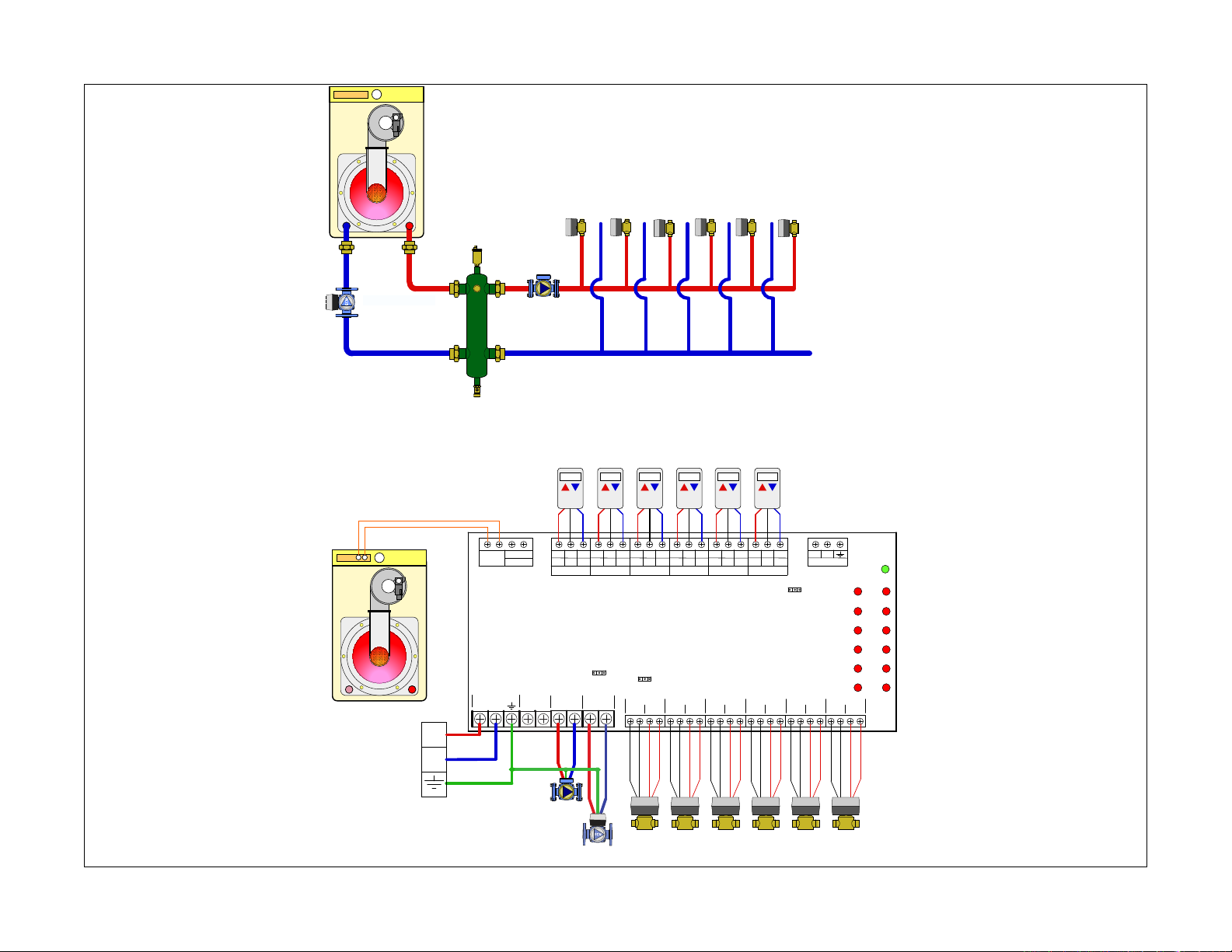
C1 - Mod/Con boiler, hydro separator, zone valves
28
Hydronic diagram is for illustration purposes only, some components have been removed for simplicity.
SYSTEM
Page 37

Description of terminals
Sequence of Operation / Settings
= Ground
N = Neutral (common leg of 120 VAC)
L = Line (live leg of 120 VAC)
Thermostat terminals
R = 24 VAC
W = Heat call
C
= Common of 24 VAC
Boiler terminals
XX = Dry contacts rated up to 120 VAC, 2 Amps.
Closes when any zone calls including priority.
Typically connected to TT on boiler control.
DHW (ZR/ZC) = Dry contacts rated up to 120 VAC,
2 Amps. Closes only when priority is enabled and
calling. Typically used to close ZR\ZC (120 VAC)
or DHW contacts (24 VAC) on boiler controls
equipped with these features.
Pump terminals
SYSTEM PUMP = Runs when any zone calls for
heat. When priority is enabled, the status of the
pump (on\off) during a priority call is selected via
a jumper
SEC PUMP = Runs when any zone calls for heat
except the priority zone when it is enabled.
PRIORITY PUMP = Runs when the priority zone
calls. A jumper is required between the END
SWITCH terminals when using a pump.
Valve terminals
Motor = 24 VAC to power the zone valve motor
End Switch = Connects to end switch on zone
valve. Must be jumpered if using a 2 –wire zone
valve.
Priority Jumper: OFF
Master / Slave Jumper: Master
Status During Priority: OFF
• A demand occurs from any T-stat (T-stat
closes TT terminals). The “T-STAT CALL” LED
illuminates for that zone.
• ZVR control sends 24 VAC to the corresponding
zone MOTOR terminals to open the zone
valve.
• When the end switch on the zone valve closes,
the control sends 120 VAC to SEC PUMP and
SYSTEM PUMP. The “VALVE OPEN” LED
illuminates for that zone and the XX contacts
close to signal a heat demand to the boiler.
• When the demand from the T-stat is satisfied
(T-stat opens TT terminals), both the “T-STAT
CALL” and “VALVE OPEN” LED’s turn off.
• 24 VAC is dropped from the corresponding
zone MOTOR terminals.
• If no other zones are calling, power is turned
off to the SEC PUMP and SYSTEM PUMP and
the XX contacts are opened.
WARNING: NEVER CONNECT R & C DIRECTLY,
this will be a direct short on the 24 VAC supply
29
Page 38
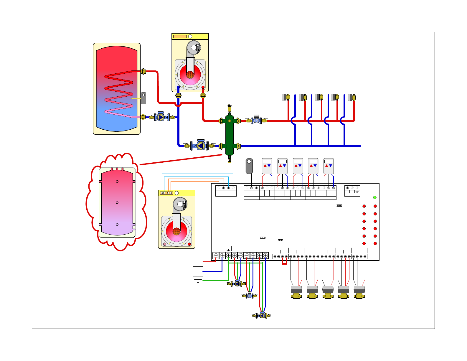
C2 - Mod/Con boiler, priority indirect DHW on primary side of hydro sep, zone valves
mod/con!
boiler
ZV4ZV3ZV2 ZV5 ZV6
DHW!
aquastat
30
Buffer tank- Optional hydraulic
separator
PRIORITY!
pump
SYSTEM!
L
N
pump
X X
POWER IN
L
SECONDARY!
pump
DHW!
AQUASTAT
DHW
ZR/ZC
N
PRIORITY
PUMP
L
PRIORITY!
pump
T T COM
T-STAT 1
SEC PUMP
L
N
SECONDARY!
pump
N
CRW
STATUS
DURING
PRIORITY
SYSTEM
L
T T COM
T-STAT 2
ON OFF
PUMP
N
CRW
PRIORITY
MOTOR
CRW
T T COM
T-STAT 3
ZVR106
6 Zone
ON OFF
ZONE 1
END
SWITCH
T T COM
T-STAT 4
ZONE 2
MOTOR
END
SWITCH
CRW
MOTOR
T T COM
T-STAT 5
ZONE 3
END
SWITCH
CRW
T T COM
T-STAT 6
ZONE 4
SWITCH
MOTOR
ZV4ZV3ZV2 ZV5 ZV6
END
CRW
MASTER SLAVE
MOTOR
ZONE 5
END
SWITCH
D
COMMS
P
MOTOR
ZONE 6
PWR
TSAT1 ZONE1
TSAT2 ZONE2
TSAT3 ZONE3
TSAT4 ZONE4
TSAT5 ZONE5
TSAT6 ZONE6
END
SWITCH
Hydronic diagram is for illustration purposes only, some components have been removed for simplicity.
SYSTEM!
pump
Page 39
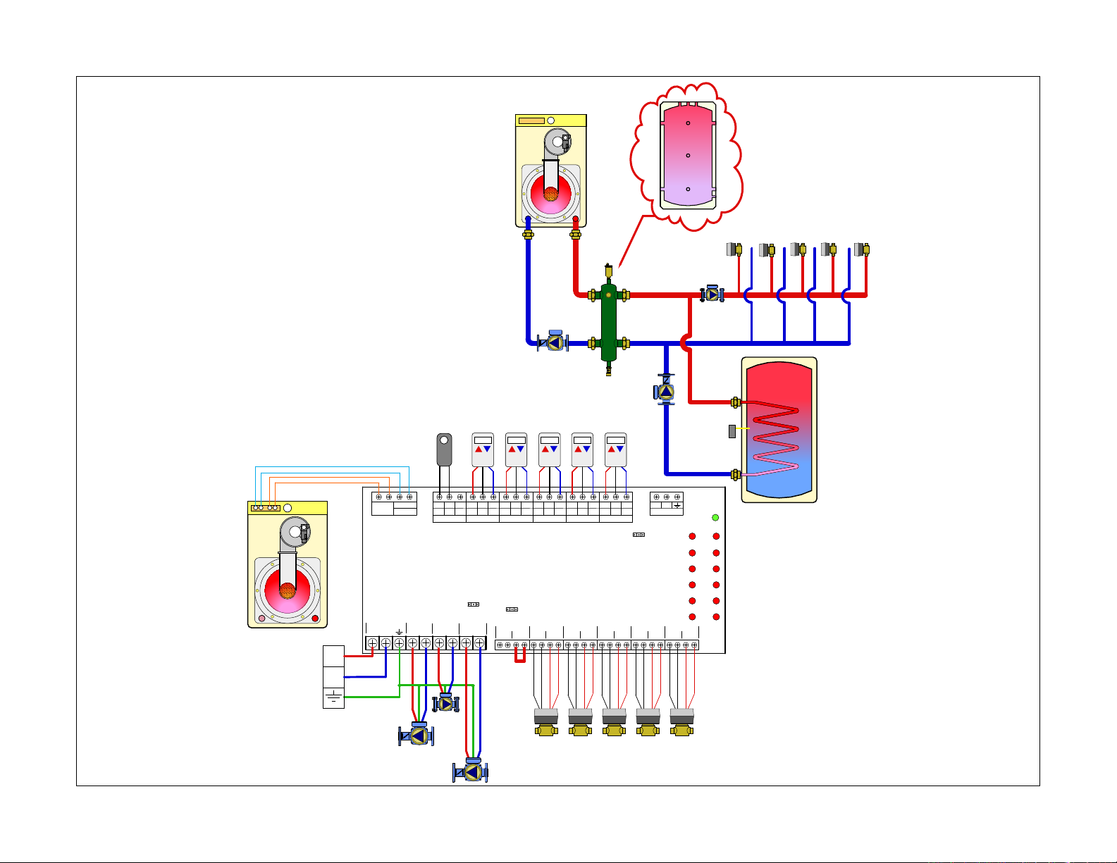
Description of terminals
Sequence of Operation / Settings
= Ground
N = Neutral (common leg of 120 VAC)
L = Line (live leg of 120 VAC)
Thermostat terminals
R = 24 VAC
W = Heat call
C
= Common of 24 VAC
Boiler terminals
XX = Dry contacts rated up to 120 VAC, 2 Amps.
Closes when any zone calls including priority.
Typically connected to TT on boiler control.
DHW (ZR/ZC) = Dry contacts rated up to 120 VAC,
2 Amps. Closes only when priority is enabled and
calling. Typically used to close ZR\ZC (120 VAC)
or DHW contacts (24 VAC) on boiler controls
equipped with these features.
Pump terminals
SYSTEM PUMP = Runs when any zone calls for
heat. When priority is enabled, the status of the
pump (on\off) during a priority call is selected via
a jumper
SEC PUMP = Runs when any zone calls for heat
except the priority zone when it is enabled.
PRIORITY PUMP = Runs when the priority zone
calls. A jumper is required between the END
SWITCH terminals when using a pump.
Valve terminals
Motor = 24 VAC to power the zone valve motor
End Switch = Connects to end switch on zone
valve. Must be jumpered if using a 2 –wire zone
valve.
WARNING: NEVER CONNECT R & C DIRECTLY,
this will be a direct short on the 24 VAC supply
• Priority Jumper: ON (Zone #1 becomes
priority)
• Master/Slave Jumper: Master
• Status During Priority: OFF
• A demand occurs from a T-stat (T-stat closes
TT terminals) in zones 2 thru 6. The “T-STAT
CALL” LED illuminates for that zone.
• ZVR control sends 24 VAC to the corresponding
zone MOTOR terminals to open the zone
valve.
• When the end switch on the zone valve closes,
the control sends 120 VAC to SEC PUMP and
SYSTEM PUMP. The “VALVE OPEN” LED
illuminates for that zone and the XX contacts
close to signal a heat demand to the boiler.
• When the demand from the T-stat is satisfied
(T-stat opens TT terminals), both the “T-STAT
CALL” and “VALVE OPEN” LED’s turn off.
• 24 VAC is dropped from the corresponding
zone MOTOR terminals.
• If no other zones are calling, power is dropped
to the SEC PUMP and SYSTEM PUMP and
the XX contacts are opened.
• If a demand occurs from the DHW aquastat
(zone #1), The “T-STAT CALL” LED illuminates
for Zone #1 and the “VALVE OPEN” LED
will illuminate. (When using a DHW pump,
a jumper must be installed on Zone #1 end
switch terminals.)
• If any other zone was calling (Zones 2 thru
6) when Zone #1 called, power (24 VAC) is
dropped to those zones.
• The XX and DHW contacts close.
• The PRIORITY PUMP contacts deliver 120
VAC
• The SEC PUMP and SYSTEM PUMP are off.
• Once the Zone #1 DHW demand is satisfied,
power to the PRIORITY PUMP is dropped, the
DHW contacts open.
• If a demand from zones 2 thru 6 is present,
24 VAC is delivered to the corresponding
zone valve(s) and the “T-STAT CALL” LED’s
illuminate.
• When the zone valve end switch closes,
the “VALVE OPEN” LED illuminates, the XX
contacts close, the SEC PUMP and SYSTEM
PUMP terminals deliver 120 VAC.
DHW Time Out \ Freeze Prevention Feature
• After one hour of a priority demand, the control
will open the DHW contacts and turn off power
to the DHW pump and Zone Valve #1.
• If a heating demand is present from Zones
#2- 6, the control will satisfy those demands
before going back to the DHW call.
• After the heating demands are met, the control
will go back to DHW and re-set the one hour
timer.
31
Page 40
C3 - Mod/Con boiler, priority indirect DHW on load side of hydro sep, zone valves
Buffer tank- Optional hydraulic
separator
32
X X
POWER IN
L
ZV4ZV3ZV2 ZV5
SECONDARY!
P
MOTOR
TSAT1 ZONE1
TSAT2 ZONE2
TSAT3 ZONE3
TSAT4 ZONE4
TSAT5 ZONE5
TSAT6 ZONE6
ZONE 6
END
SWITCH
pump
PWR
DHW!
AQUASTAT
SYSTEM!
pump
PRIORITY!
pump
DHW!
AQUASTAT
DHW
ZR/ZC
T T COM
T-STAT 1
PRIORITY
SEC PUMP
PUMP
N
L
N
L
CRW
CRW
T T COM
T-STAT 2
STATUS
DURING
PRIORITY
ON OFF
SYSTEM
PUMP
N
L
N
T T COM
T-STAT 3
ZVR106
PRIORITY
ON OFF
ZONE 1
MOTOR
6 Zone
END
SWITCH
CRW
MOTOR
T T COM
T-STAT 4
ZONE 2
END
SWITCH
CRW
T T COM
T-STAT 5
ZONE 3
MOTOR
END
SWITCH
CRW
T T COM
T-STAT 6
ZONE 4
MOTOR
SWITCH
END
CRW
MASTER SLAVE
MOTOR
ZONE 5
SWITCH
D
END
COMMS
ZV6
L
N
Hydronic diagram is for illustration purposes only, some components have been removed for simplicity.
Page 41
Description of terminals
Sequence of Operation / Settings
= Ground
N = Neutral (common leg of 120 VAC)
L = Line (live leg of 120 VAC)
Thermostat terminals
R = 24 VAC
W = Heat call
C
= Common of 24 VAC
Boiler terminals
XX = Dry contacts rated up to 120 VAC, 2 Amps.
Closes when any zone calls including priority.
Typically connected to TT on boiler control.
DHW (ZR/ZC) = Dry contacts rated up to 120 VAC,
2 Amps. Closes only when priority is enabled and
calling. Typically used to close ZR\ZC (120 VAC)
or DHW contacts (24 VAC) on boiler controls
equipped with these features.
Pump terminals
SYSTEM PUMP = Runs when any zone calls for
heat. When priority is enabled, the status of the
pump (on\off) during a priority call is selected via
a jumper
SEC PUMP = Runs when any zone calls for heat
except the priority zone when it is enabled.
PRIORITY PUMP = Runs when the priority zone
calls. A jumper is required between the END
SWITCH terminals when using a pump.
Valve terminals
Motor = 24 VAC to power the zone valve motor
End Switch = Connects to end switch on zone
valve. Must be jumpered if using a 2 –wire zone
valve.
WARNING: NEVER CONNECT R & C DIRECTLY,
this will be a direct short on the 24 VAC supply
Priority Jumper: ON (Zone #1 becomes priority)
Master/Slave Jumper: Master
Status During Priority: ON
• A demand occurs from a T-stat (T-stat closes
TT terminals) in zones 2 thru 6. The “T-STAT
CALL” LED illuminates for that zone.
• ZVR control sends 24 VAC to the corresponding
zone MOTOR terminals to open the zone
valve.
• When the end switch on the zone valve closes,
the control sends 120 VAC to SEC PUMP and
SYSTEM PUMP. The “VALVE OPEN” LED
illuminates for that zone and the XX contacts
close to signal a heat demand to the boiler.
• When the demand from the T-stat is satisfied
(T-stat opens TT terminals), both the “T-STAT
CALL” and “VALVE OPEN” LED’s turn off.
• 24 VAC is dropped from the corresponding
zone MOTOR terminals.
• If no other zones are calling, power is dropped
to the SEC PUMP and SYSTEM PUMP and
the XX contacts are opened.
• If a demand occurs from the DHW aquastat
(zone #1), The “T-STAT CALL” LED illuminates
for Zone #1 and the “VALVE OPEN” LED
will illuminate. (When using a DHW pump,
a jumper must be installed on Zone #1 end
switch terminals.)
• If any other zone was calling (Zones 2 thru
6) when Zone #1 called, power (24 VAC) is
dropped to those zones.
• The XX and DHW contacts close.
• The PRIORITY PUMP and SYSTEM PUMP
contacts deliver 120 VAC
• The SEC PUMP is off.
• Once the Zone #1 DHW demand is satisfied,
power to the PRIORITY PUMP and SYSTEM
PUMP is dropped, the DHW contacts open.
• If a demand from zones 2 thru 6 is present,
24 VAC is delivered to the corresponding
zone valve(s) and the “T-STAT CALL” LED’s
illuminate.
• When the zone valve end switch closes,
the “VALVE OPEN” LED illuminates, the XX
contacts close, the SEC PUMP and SYSTEM
PUMP terminals deliver 120 VAC.
DHW Time Out \ Freeze Prevention Feature
• After one hour of a priority demand, the control
will open the DHW contacts and turn off power
to the DHW pump and Zone Valve #1.
• If a heating demand is present from Zones
#2- 6, the control will satisfy those demands
before going back to the DHW call.
• After the heating demands are met, the control
will go back to DHW for and re-set the one
hour timer.
33
Page 42
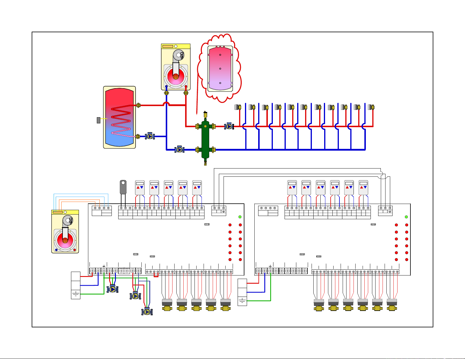
C4- Mod/Con boiler, priority indirect DHW on primary side of hydro sep, expansion control
pump
Buffer tank - Optional hydraulic
separator
34
DHW!
AQUASTAT
X X
POWER IN
L
L
ZV4ZV3
X X
POWER IN
N
DHW
ZR/ZC
ZV5
PRIORITY
PUMP
L
N
ZV6
T T COM
T-STAT 1
SEC PUMP
L
ZV7
CRW
CRW
T T COM
T-STAT 2
STATUS
DURING
PRIORITY
ON OFF
SYSTEM
PUMP
N
L
N
MOTOR
ZV2
SECONDARY!
pump
PRIORITY!
pump
SYSTEM!
pump
DHW!
AQUASTAT
DHW
ZR/ZC
T T COM
T-STAT 1
PRIORITY
SEC PUMP
PUMP
N
L
N
L
CRW
CRW
T T COM
T-STAT 2
STATUS
DURING
PRIORITY
ON OFF
SYSTEM
PUMP
N
L
N
T T COM
T-STAT 3
PRIORITY
ZONE 1
MOTOR
ON OFF
CRW
T T COM
T-STAT 4
ZVR106
6 Zone
ZONE 2
END
SWITCH
MOTOR
END
SWITCH
CRW
T T COM
T-STAT 5
ZONE 3
MOTOR
SWITCH
CRW
T T COM
T-STAT 6
ZONE 4
END
MOTOR
END
SWITCH
CRW
MASTER SLAVE
MOTOR
ZONE 5
END
SWITCH
D
COMMS
P
MOTOR
ZONE 6
TSAT1 ZONE1
TSAT2 ZONE2
TSAT3 ZONE3
TSAT4 ZONE4
TSAT5 ZONE5
TSAT6 ZONE6
END
SWITCH
PWR
T T COM
T-STAT 3
ZVR106
6 Zone
PRIORITY
ON OFF
ZONE 1
END
SWITCH
CRW
MOTOR
ZV9ZV8
T T COM
T-STAT 4
ZONE 2
END
SWITCH
CRW
ZV10
T T COM
T-STAT 5
ZONE 3
MOTOR
END
SWITCH
ZV11
CRW
T T COM
T-STAT 6
ZONE 4
MOTOR
SWITCH
END
ZV12
CRW
MASTER SLAVE
MOTOR
ZONE 5
END
SWITCH
D
COMMS
P
MOTOR
TSAT1 ZONE1
TSAT2 ZONE2
TSAT3 ZONE3
TSAT4 ZONE4
TSAT5 ZONE5
TSAT6 ZONE6
ZONE 6
END
SWITCH
PWR
L
N
PRIORITY!
pump
Hydronic diagram is for illustration purposes only, some components have been removed for simplicity.
SECONDARY!
pump
SECONDARY
pump
SYSTEM!
pump
SYSTEM
ZV4ZV3ZV2 ZV5 ZV6
L
N
ZV7
ZV10ZV9ZV8 ZV11 ZV12
Page 43
Description of terminals
= Ground
N = Neutral (common leg of 120 VAC)
L = Line (live leg of 120 VAC)
Thermostat terminals
R = 24 VAC
W = Heat call
C
= Common of 24 VAC
Boiler terminals
XX = Dry contacts rated up to 120 VAC, 2 Amps.
Closes when any zone calls including priority.
Typically connected to TT on boiler control.
DHW (ZR/ZC) = Dry contacts rated up to 120 VAC,
2 Amps. Closes only when priority is enabled and
calling. Typically used to close ZR\ZC (120 VAC)
or DHW contacts (24 VAC) on boiler controls
equipped with these features.
Pump terminals
SYSTEM PUMP = Runs when any zone calls for
heat. When priority is enabled, the status of the
pump (on\off) during a priority call is selected via
a jumper
SEC PUMP = Runs when any zone calls for heat
except the priority zone when it is enabled.
PRIORITY PUMP = Runs when the priority zone
calls. A jumper is required between the END
SWITCH terminals when using a pump.
Valve terminals
Motor = 24 VAC to power the zone valve motor
End Switch = Connects to end switch on zone
valve. Must be jumpered if using a 2 –wire zone
valve.
WARNING: NEVER CONNECT R & C DIRECTLY,
this will be a direct short on the 24 VAC supply
Sequence of Operation / Settings
Control #1 (Master)
Priority Jumper: ON (Zone #1 becomes priority)
Master/Slave Jumper: Master
Status During Priority: OFF
Control #2 (Slave)
Priority Jumper: OFF
Master/Slave Jumper: Slave
Status During Priority: OFF
• A demand occurs from a T-stat (T-stat closes
TT terminals) in zones 2 thru 12. The “T-STAT
CALL” LED illuminates for that zone.
• ZVR control sends 24 VAC to the corresponding
zone MOTOR terminals to open the zone
valve.
• When the end switch on the zone valve closes,
the control sends 120 VAC to SEC PUMP and
SYSTEM PUMP. The “VALVE OPEN” LED
illuminates for that zone and the XX contacts
close to signal a heat demand to the boiler.
NOTE: The SEC PUMP output is only fired on the
control that receives the t-stat call. For instance,
if a zone from control #1 calls, the SEC PUMP on
control #1 fires but SEC PUMP on control #2 does
not. When using a single secondary pump with 2
controls, the secondary pump must be connected
to the “SYSTEM PUMP” terminals. (An alternative
wiring option for secondary pump is to wire the
secondary pump to the “SEC PUMP” terminals of
both controls).
• When the demand from the T-stat is satisfied
(T-stat opens TT terminals), both the “T-STAT
CALL” and “VALVE OPEN” LED’s turn off.
• 24 VAC is dropped from the corresponding
zone MOTOR terminals.
• If no other zones are calling, power is dropped
to the SEC PUMP and SYSTEM PUMP and
the XX contacts are opened.
• If a demand occurs from the DHW aquastat
(zone #1), The “T-STAT CALL” LED illuminates
for Zone #1 and the “VALVE OPEN” LED
will illuminate. (When using a DHW pump,
a jumper must be installed on Zone #1 end
switch terminals.)
• If any other zone was calling (Zones 2 thru
12) when Zone #1 called, power (24 VAC) is
dropped to those zones.
• The XX and DHW contacts close.
• The PRIORITY PUMP contacts deliver 120
VAC
• The SEC PUMP and SYSTEM PUMP are off.
• Once the Zone #1 DHW demand is satisfied,
power to the PRIORITY PUMP is dropped, the
DHW contacts open.
• If a demand from zones 2 thru 12 is present,
24 VAC is delivered to the corresponding
zone valve(s) and the “T-STAT CALL” LED’s
illuminate.
• When the zone valve end switch closes,
the “VALVE OPEN” LED illuminates, the XX
contacts close, the SEC PUMP and SYSTEM
PUMP terminals deliver 120 VAC.
• DHW Time Out \ Freeze Prevention Feature
• After one hour of a priority demand, the control
will open the DHW contacts and turn off power
to the DHW pump and Zone Valve #1.
• If a heating demand is present from Zones
#2- 12, the control will satisfy those demands
before going back to the DHW call.
• After the heating demands are met, the control
will go back to DHW for and re-set the one
hour timer.
35
Page 44
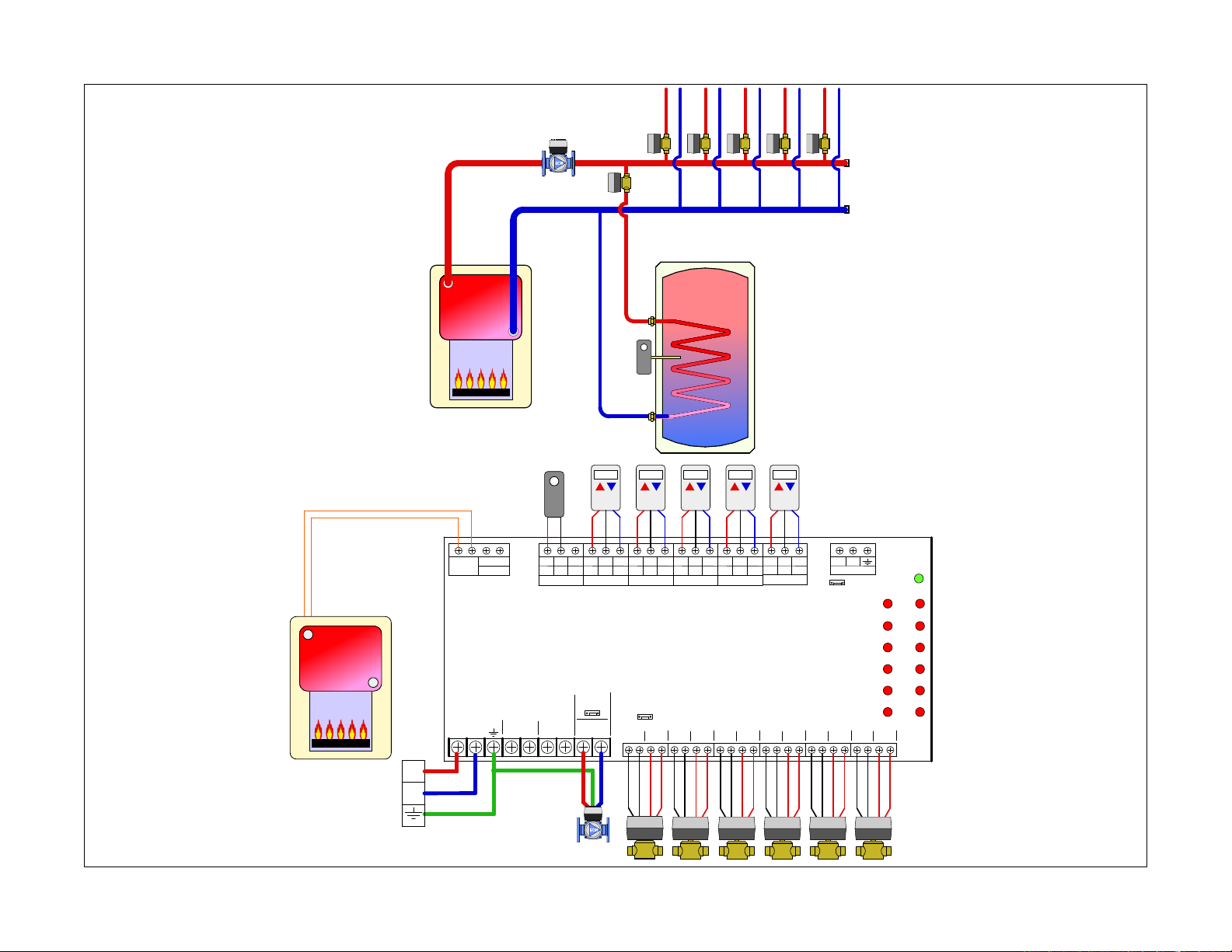
C5 - Traditional boiler, indirect DHW (no priority) with valve, zone valves
36
X X
POWER IN
L
SYSTEM!
pump
ZV2
ZV3
ZV4
ZV5
ZV6
ZV1
DHW!
aquastat
DHW
ZR/ZC
T T COM
THM 1
CRW
T T COM
THM 2
CRW
T T COM
THM 3
CRW
T T COM
THM 4
CRW
T T COM
THM 5
CRW
T T COM
THM 6
ZRV106
6 Zone
Z6V
STATUS
DURING
SEC PUMP
L
PRIORITY
SYSTEM
PUMP
N
PRIORITY
PUMP
N
N
L
PRIORITY
MOTOR
ZONE 1
END
SWITCH
MOTOR
ZONE 2
END
SWITCH
MOTOR
ZONE 3
END
SWITCH
MOTOR
ZONE 4
SWITCH
D
CRW
Master/Slave
P
COMMS
PWR
THM1 ZONE1
THM2 ZONE2
THM3 ZONE3
THM4 ZONE4
THM5 ZONE5
THM6 ZONE6
ZONE 5
ZONE 6
END
END
SWITCH
MOTOR
MOTOR
END
SWITCH
L
N
Hydronic diagram is for illustration purposes only, some components have been removed for simplicity.
Page 45

Description of terminals
Sequence of Operation / Settings
= Ground
N = Neutral (common leg of 120 VAC)
L = Line (live leg of 120 VAC)
Thermostat terminals
R = 24 VAC
W = Heat call
C
= Common of 24 VAC
Boiler terminals
XX = Dry contacts rated up to 120 VAC, 2 Amps.
Closes when any zone calls including priority.
Typically connected to TT on boiler control.
DHW (ZR/ZC) = Dry contacts rated up to 120 VAC,
2 Amps. Closes only when priority is enabled and
calling. Typically used to close ZR\ZC (120 VAC)
or DHW contacts (24 VAC) on boiler controls
equipped with these features.
Pump terminals
SYSTEM PUMP = Runs when any zone calls for
heat. When priority is enabled, the status of the
pump (on\off) during a priority call is selected via
a jumper
SEC PUMP = Runs when any zone calls for heat
except the priority zone when it is enabled.
PRIORITY PUMP = Runs when the priority zone
calls. A jumper is required between the END
SWITCH terminals when using a pump.
Valve terminals
Motor = 24 VAC to power the zone valve motor
End Switch = Connects to end switch on zone
valve. Must be jumpered if using a 2 –wire zone
valve.
Priority Jumper: OFF
Master/Slave Jumper: Master
Status During Priority: OFF
• A demand occurs from a T-stat (T-stat
closes TT terminals) in zones 2 thru 6 otr the
aquastat on zone #1. The “T-STAT CALL” LED
illuminates for that zone.
• ZVR control sends 24 VAC to the corresponding
zone MOTOR terminals to open the zone
valve.
• When the end switch on the zone valve closes,
the control sends 120 VAC to SEC PUMP and
SYSTEM PUMP. The “VALVE OPEN” LED
illuminates for that zone and the XX contacts
close to signal a heat demand to the boiler.
• When the demand from the T-stat is satisfied
(T-stat opens TT terminals), both the “T-STAT
CALL” and “VALVE OPEN” LED’s turn off.
• 24 VAC is dropped from the corresponding
zone MOTOR terminals.
• If no other zones are calling, power is turned
off to the SEC PUMP and SYSTEM PUMP and
the XX contacts are opened.
WARNING: NEVER CONNECT R & C DIRECTLY,
this will be a direct short on the 24 VAC supply
37
Page 46
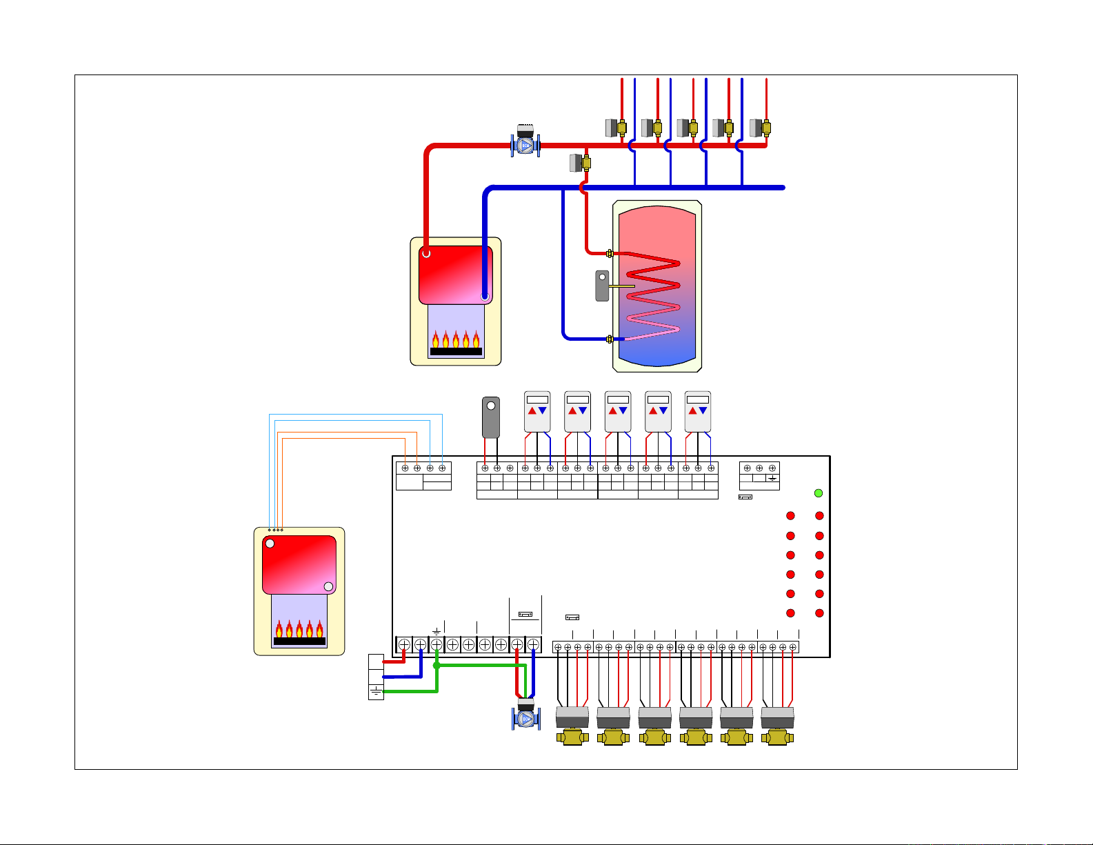
C6- Traditional boiler with reset control, priority indirect DHW with valve, zone valves
38
SYSTEM!
pump
ZV2
ZV3
ZV4
ZV5
ZV6
ZV1
DHW!
aquastat
DHW!
aquastat
DHW
X X
ZR/ZC
ZR
ZC
T T
T T COM
THM 1
CRW
T T COM
THM 2
CRW
T T COM
THM 3
ZRV106
CRW
T T COM
THM 4
CRW
T T COM
THM 5
CRW
T T COM
THM 6
6 Zone
Z6V
STATUS
DURING
POWER IN
L
SEC PUMP
L
PRIORITY
SYSTEM
PUMP
N
PRIORITY
PUMP
N
N
L
PRIORITY
MOTOR
ZONE 1
END
SWITCH
MOTOR
ZONE 2
END
SWITCH
MOTOR
ZONE 3
END
SWITCH
MOTOR
ZONE 4
END
SWITCH
D
CRW
COMMS
Master/Slave
P
PWR
THM1 ZONE1
THM2 ZONE2
THM3 ZONE3
THM4 ZONE4
THM5 ZONE5
THM6 ZONE6
ZONE 5
ZONE 6
END
MOTOR
END
SWITCH
MOTOR
SWITCH
L
N
Hydronic diagram is for illustration purposes only, some components have been removed for simplicity.
Page 47
Description of terminals
Sequence of Operation
= Ground
N = Neutral (common leg of 120 VAC)
L = Line (live leg of 120 VAC)
Thermostat terminals
R = 24 VAC
W = Heat call
C
= Common of 24 VAC
Boiler terminals
XX = Dry contacts rated up to 120 VAC, 2 Amps.
Closes when any zone calls including priority.
Typically connected to TT on boiler control.
DHW (ZR/ZC) = Dry contacts rated up to 120 VAC,
2 Amps. Closes only when priority is enabled and
calling. Typically used to close ZR\ZC (120 VAC)
or DHW contacts (24 VAC) on boiler controls
equipped with these features.
Pump terminals
SYSTEM PUMP = Runs when any zone calls for
heat. When priority is enabled, the status of the
pump (on\off) during a priority call is selected via
a jumper
SEC PUMP = Runs when any zone calls for heat
except the priority zone when it is enabled.
PRIORITY PUMP = Runs when the priority zone
calls. A jumper is required between the END
SWITCH terminals when using a pump.
Valve terminals
Motor = 24 VAC to power the zone valve motor
End Switch = Connects to end switch on zone
valve. Must be jumpered if using a 2 –wire zone
valve.
WARNING: NEVER CONNECT R & C DIRECTLY,
this will be a direct short on the 24 VAC supply
Priority Jumper: ON (Zone #1 becomes priority)
Master/Slave Jumper: Master
Status During Priority: ON
• A demand occurs from a T-stat (T-stat closes
TT terminals) in zones 2 thru 6. The “T-STAT
CALL” LED illuminates for that zone.
• ZVR control sends 24 VAC to the corresponding
zone MOTOR terminals to open the zone
valve.
• When the end switch on the zone valve closes,
the control sends 120 VAC to SEC PUMP and
SYSTEM PUMP. The “VALVE OPEN” LED
illuminates for that zone and the XX contacts
close to signal a heat demand to the boiler.
• When the demand from the T-stat is satisfied
(T-stat opens TT terminals), both the “T-STAT
CALL” and “VALVE OPEN” LED’s turn off.
• 24 VAC is dropped from the corresponding
zone MOTOR terminals.
• If no other zones are calling, power is dropped
to the SEC PUMP and SYSTEM PUMP and
the XX contacts are opened.
• If a demand occurs from the DHW aquastat
(zone #1), The “T-STAT CALL” LED illuminates
for Zone #1 and the “VALVE OPEN” LED
will illuminate. (When using a DHW pump,
a jumper must be installed on Zone #1 end
switch terminals.)
• If any other zone was calling (Zones 2 thru
6) when Zone #1 called, power (24 VAC) is
dropped to those zones.
• The XX and DHW contacts close.
• The PRIORITY PUMP and SYSTEM PUMP
contacts deliver 120 VAC
• The SEC PUMP is off.
• Once the Zone #1 DHW demand is satisfied,
power to the PRIORITY PUMP and SYSTEM
PUMP is dropped, the DHW contacts open.
• If a demand from zones 2 thru 6 is present,
24 VAC is delivered to the corresponding
zone valve(s) and the “T-STAT CALL” LED’s
illuminate.
• When the zone valve end switch closes,
the “VALVE OPEN” LED illuminates, the XX
contacts close, the SEC PUMP and SYSTEM
PUMP terminals deliver 120 VAC.
DHW Time Out \ Freeze Prevention Feature
• After one hour of a priority demand, the control
will open the DHW contacts and turn off power
to the DHW pump and Zone Valve #1.
• If a heating demand is present from Zones
#2- 6, the control will satisfy those demands
before going back to the DHW call.
• After the heating demands are met, the control
will go back to DHW and re-set the one hour
timer.
39
Page 48
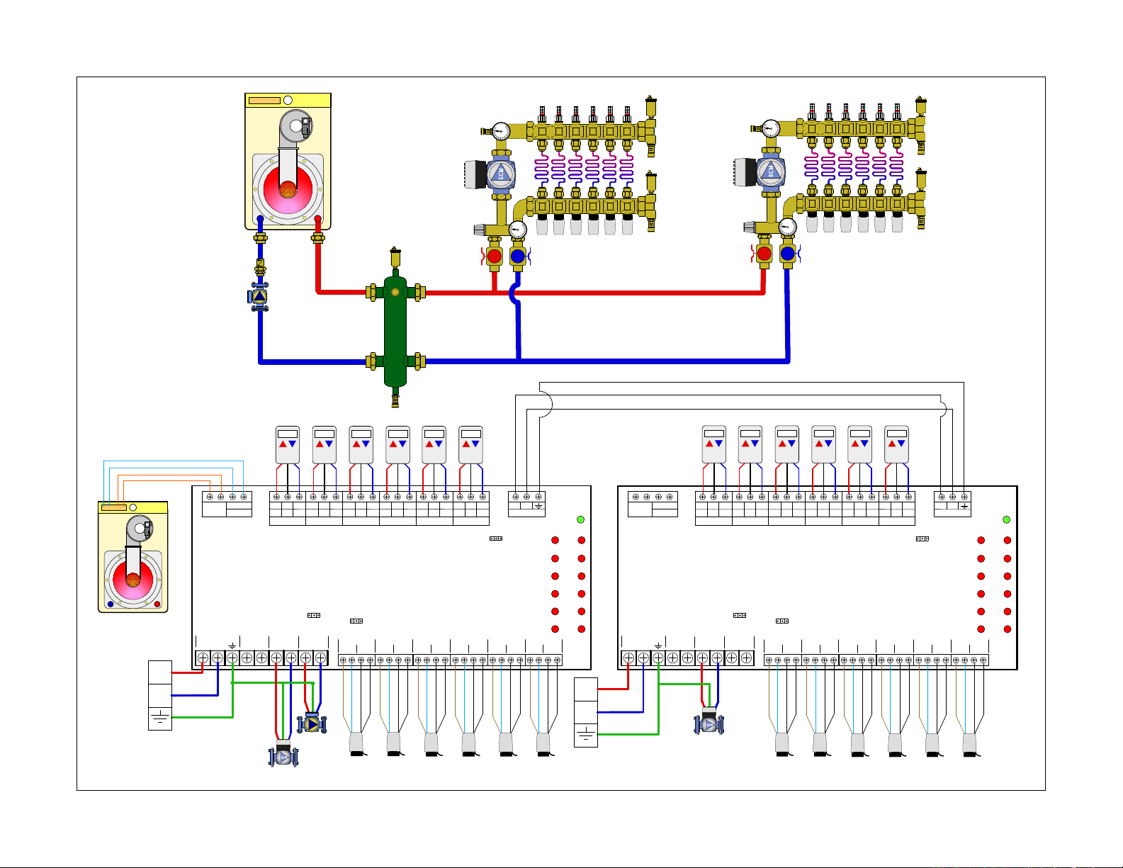
6 Zone
ZVR106
T-STAT 2
CRW
T T COM
COMMS
D
P
DHW
ZR/ZC
X X
T-STAT 3
CRW
T T COM
T-STAT 1
CRW
T T COM
L
POWER IN
N
T-STAT 4
CRW
T T COM
T-STAT 5
CRW
T T COM
T-STAT 6
CRW
T T COM
PWR
TSAT1 ZONE1
TSAT2 ZONE2
TSAT3 ZONE3
TSAT4 ZONE4
TSAT5 ZONE5
TSAT6 ZONE6
L
PRIORITY
PUMP
N
L
SEC PUMP
N
STATUS
DURING
PRIORITY
ZONE 1
END
SWITCH
MOTOR
PRIORITY
ZONE 2
END
SWITCH
MOTOR
ZONE 3
END
SWITCH
MOTOR
ZONE 4
END
SWITCH
MOTOR
ZONE 5
END
SWITCH
MOTOR
ZONE 6
END
SWITCH
MOTOR
ON OFF
ON OFF
L
SYSTEM
PUMP
N
MASTER SLAVE
6 Zone
ZVR106
T-STAT 2
CRW
T T COM
COMMS
D
P
DHW
ZR/ZC
X X
T-STAT 3
CRW
T T COM
T-STAT 1
CRW
T T COM
L
POWER IN
N
T-STAT 4
CRW
T T COM
T-STAT 5
CRW
T T COM
T-STAT 6
CRW
T T COM
PWR
TSAT1 ZONE1
TSAT2 ZONE2
TSAT3 ZONE3
TSAT4 ZONE4
TSAT5 ZONE5
TSAT6 ZONE6
L
PRIORITY
PUMP
N
L
SEC PUMP
N
STATUS
DURING
PRIORITY
ZONE 1
END
SWITCH
MOTOR
PRIORITY
ZONE 2
END
SWITCH
MOTOR
ZONE 3
END
SWITCH
MOTOR
ZONE 4
END
SWITCH
MOTOR
ZONE 5
END
SWITCH
MOTOR
ZONE 6
END
SWITCH
MOTOR
ON OFF
ON OFF
L
SYSTEM
PUMP
N
MASTER SLAVE
L
N
"A"!
pump
SYSTEM!
pump
A4A3A2 A5 A6
"B"!
pump
SYSTEM!
pump
"A"!
pump
"B"!
pump
A1
A10A9A8 A11 A12A7
A4A3A2 A5 A6A1
A10A9A8 A11A12A7
L
N
C7 - Mod/Con boiler, hydro separator, zone valves (more than 6), multiple secondary pumps
40
Hydronic diagram is for illustration purposes only, some components have been removed for simplicity.
Page 49
Description of terminals
Sequence of Operation / Settings
= Ground
N = Neutral (common leg of 120 VAC)
L = Line (live leg of 120 VAC)
Thermostat terminals
R = 24 VAC
W = Heat call
C
= Common of 24 VAC
Boiler terminals
XX = Dry contacts rated up to 120 VAC, 2 Amps.
Closes when any zone calls including priority.
Typically connected to TT on boiler control.
DHW (ZR/ZC) = Dry contacts rated up to 120 VAC,
2 Amps. Closes only when priority is enabled and
calling. Typically used to close ZR\ZC (120 VAC)
or DHW contacts (24 VAC) on boiler controls
equipped with these features.
Pump terminals
SYSTEM PUMP = Runs when any zone calls for
heat. When priority is enabled, the status of the
pump (on\off) during a priority call is selected via
a jumper
SEC PUMP = Runs when any zone calls for heat
except the priority zone when it is enabled.
PRIORITY PUMP = Runs when the priority zone
calls. A jumper is required between the END
SWITCH terminals when using a pump.
Valve terminals
Motor = 24 VAC to power the zone valve motor
End Switch = Connects to end switch on zone
valve. Must be jumpered if using a 2 –wire zone
valve.
Control #1 (Master)
Priority Jumper: OFF
Master/Slave Jumper: Master
Status During Priority: OFF
Control #2 (Slave)
Priority Jumper: OFF
Master/Slave Jumper: Slave
Status During Priority: OFF
• A demand occurs from a T-stat (T-stat closes
TT terminals) in zones 1 thru 12. The “T-STAT
CALL” LED illuminates for that zone.
• ZVR control sends 24 VAC to the corresponding
zone MOTOR terminals to open the zone
valve.
• When the end switch on the zone valve closes,
the control sends 120 VAC to SYSTEM PUMP
and to the SEC PUMP located on the ZVR
control that is seeing the demand. The “VALVE
OPEN” LED illuminates for that zone and the
XX contacts close to signal a heat demand to
the boiler.
NOTE: The SEC PUMP output is only fired on the
control that receives the t-stat call. For instance,
if a zone from control #1 calls, the SEC PUMP on
control #1 fires but SEC PUMP on control #2 does
not.
• When the demand from the T-stat is satisfied
(T-stat opens TT terminals), both the “T-STAT
CALL” and “VALVE OPEN” LED’s turn off.
• If no other zones are calling, power is turned
off to the SEC PUMP and SYSTEM PUMP and
the XX contacts are opened.
WARNING: NEVER CONNECT R & C DIRECTLY,
this will be a direct short on the 24 VAC supply
• 24 VAC is dropped from the corresponding
zone MOTOR terminals.
41
Page 50

42
Calef North America, Inc. / 3883 W Milwaukee Rd / Milwaukee, WI 53208
Tel: 414.238.2360 / Fax: 44.238.2366
www.calef.com/usa / sales@calef.com
©Copyright 2014 Calef North America, Inc
 Loading...