

Page 1
Z series
R
E
G
I
S
T
E
R
E
D
B
S EN ISO 9001:2000
C
ert. n∞ FM 21654
U
NI
zone valves
CALEFFI
01115/11 NA
Replaces 01115/10 NA
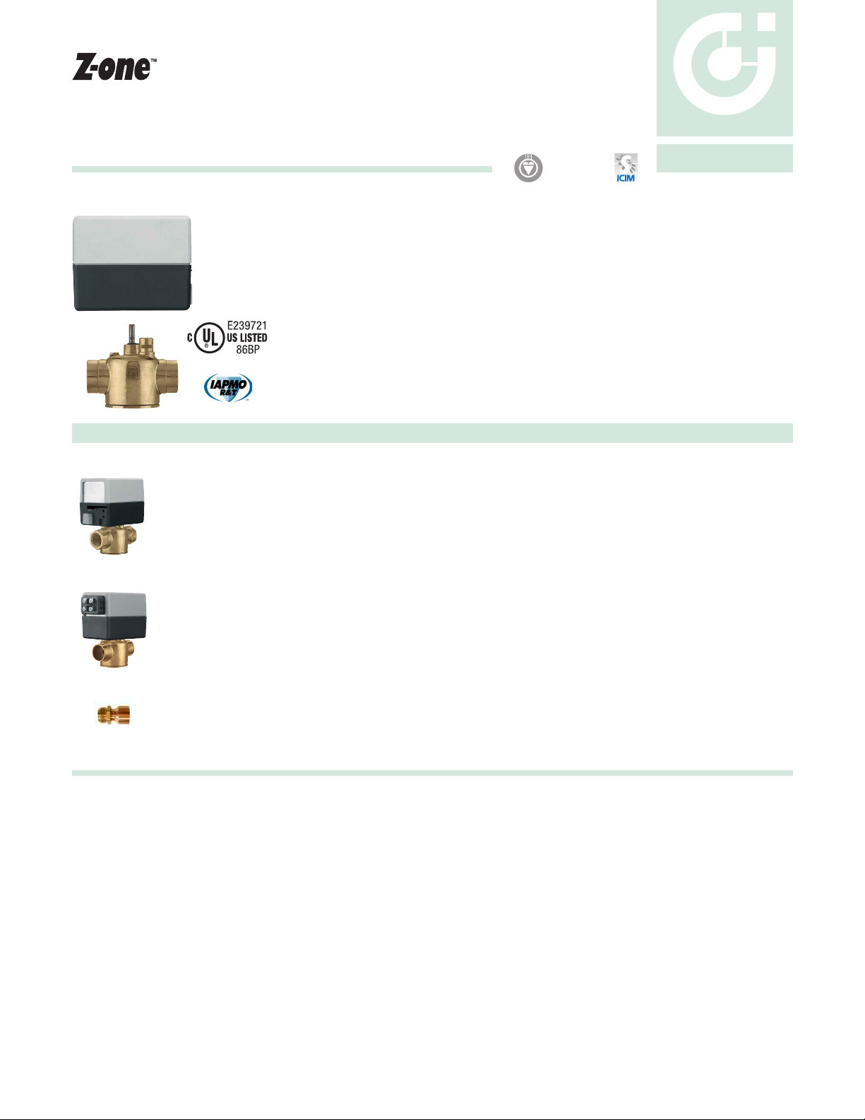
Function
Z-one valves are used to automatically shut-off the flow or redirect hot and chilled water in hydronic
heating and air conditioning systems, and is UL listed for plenum installations.
The motorized two position, on/off, spring return Z1 series actuator has an end mounted push button
for quick installation to valve body. The actuator is equipped with or without auxiliary switch and
configured Normally Closed or Normally Opened with wire or terminal connections.
The zero leakage high temperature zone valve body Z2 series is 2-way straight through and the valve
body Z3 series is 3-way diverting. The Z1 series actuator is easily attached by a push button lock and
without tools.
The high temperature and high close-off performance characteristics of these zone valves, combined
with the compact size, makes them suitable to fit inside baseboard or directly in fan coils units.
• US Patent 7,048,251; others pending
Quick Order Code Numbers: 24VAC Normally Closed Actuator and 2-way Valve Body Combinations
Code Description Connection
Z32 Z121000 without auxiliary switch, 18 inch wire connection + Z200053 flare body 1/2” SAE
Z32F Z121000 without auxiliary switch, 18 inch wire connection + Z200053 flare body + NA10124 sweat 3/4"
Z40 Z111000 with auxiliary switch, 18 inch wire connection + Z200043 flare body + NA61241 Inverted
Z40F Z111000 with auxiliary switch, 18 inch wire connection + Z200043 flare body + two NA10006 sweat 3/4”
Z42 Z111000 with auxiliary switch, 18 inch wire connection + Z200053 flare body 1/2” SAE
Z42F Z111000 with auxiliary switch, 18 inch wire connections + Z200053 flare body + NA10124 sweat 3/4"
Z44 Z111000 with auxiliary switch, 18 inch wire connection + Z200432 sweat body 1/2”
Z45 Z111000 with auxiliary switch, 18 inch wire connection + Z200537 sweat body 3/4”
Z46 Z111000 with auxiliary switch, 18 inch wire connection + Z200637 sweat body 1”
Z47 Z111000 with auxiliary switch, 18 inch wire connection + Z200737 sweat body 1 1/4”
Z50 Z151000 with auxiliary switch, screw terminal connection + Z200043 flare body + NA61241K Inverted
Z50F Z151000 with auxiliary switch, screw terminal connection + Z200043 flare body + two NA10006 sweat 3/4”
Z54 Z151000 with auxiliary switch, screw terminal connection + Z200432 sweat body 1/2”
Z55 Z151000 with auxiliary switch, screw terminal connection + Z200537 sweat body 3/4”
Z56 Z151000 with auxiliary switch, screw terminal connection + Z200637 sweat body 1”
Z57 Z151000 with auxiliary switch, screw terminal connection + Z200737 sweat body 1 1/4”
NA10005 Inverted flare nut with attached copper sweat tail piece 1/2”
NA10006 Inverted flare nut with attached copper sweat tail piece 3/4”
NA10007 Inverted flare nut with attached copper sweat tail piece 1”
NA61241 Inverted flare extension adaptor to retrofit body into an old style asymmetrical zone valve opening Inverted
NA10124 SAE flare nut with attached copper sweat tail piece 3/4”
Technical specification
Valve body
Material: - body: forged brass (optional lead-free brass)
- seat: machined brass
- stem: stainless steel
- two o-ring seals and paddle: EPDM
Flow: 1 to 7.5 Cv (0.9 to 115°C)
Medium: water and glycol, low pressure steam
Maximum percent of glycol: 50%
Temperature range: 32 to 240°F (0 to 115°C)
Max. static pressure: 15 psi (1 bar) steam
300 psi (20 bar)
Max. closeoff ∆ pressure: 20 to 75 psi (138 to 517 kPa)
Connection: - sweat: 1/2”, 3/4” 1” & 1 1/4”
- NPT female: 1/2”, 3/4” & 1”
- SAE flare: 1/2"
- inverted flare: 1/2", 3/4" & 1" sweat
fittings separate
Approvals: for lead-free brass Lead plumbing law compliance
(0.25% Max. weighted average lead content),
Lead plumbing law certified by IAPMO R&T
Actuator
Material: - base and cover: polycarbonate
- base plate: aluminum
Motor: - AC voltage:
24 V - 120 V - 208 V - 230 V - 277 V; 50/60 Hz
Power requirements: 5.0 W, 7 VA
Power connections: - Terminal screws with auxiliary switch: 24 V only
- Wire lead length: 18” (45 cm), 24 V only
6” (15 cm), 120, 208, 230, 277 V
Auxiliary switch: 0.0 A min, 0.4 A max, 24 V (24V only)
0.25 A min, 5 A max, 250 V (Z111000 HCS)
0.25 A min, 5.0 A max, 250 V (120, 208, 230, 277 V actuators)
Ambient temperature range: 32 to 104°F (0 to 40°C) 24, 120 V
32 to 170°F (0 to 77°C) 208, 230, 277 V
Humidity: 95% non-condensing
Full Stroke Time: - On: <60 seconds
- Off: 6 seconds
Approvals: UL873, cUL Listed & CE
UL 1995 sec. 18 approved for air plenums and ducts,
Normally Open Actuators must be powered down during off-season
Page 2
AB
AB
AB
AB
LOAD
AB
LOAD
BA
LOAD
AB
BA
LOAD
AB
BA
(
N
C
)
AB
AB
(NC)(
NO
)
Dimensions
Connections
2- way 1/2” SAE Flare
3- way 1/2” SAE Flare
A
2
11/32”
2
11/32”
B
4
11/16”
4
11/16”
C
15/16”
2
1/8”
D
3
1/2”
3
1/2”
Connections
1
/2” sweat
3/4” sweat
1
” sweat
1
1/4”
sweat
A
1
5
/16
”
1
3/8”
1
11/16”
1
13/16”
B
2
5
/8
”
2
3/4”
3
3/8”
3
5/8”
C
1
5/16
”
15/16”
15/16”
15/16”
D
1
5
/16
”
1
1/2”
1
9/16”
1
11/16”
E
3
1
/2
”
3
1/2”
3
11/16”
3
11/16”
B
A
* Terminal block only
Connections
1/2” NPT
3/4” NPT
1” NPT
Inverted flare
with adaptor (NA61241K)
A
1
7/16”
1
9/16”
1
13/16”
1
3/8”
1
3/8”
B
2
7/8”
3
1/16”
3
5/8”
2
3/4”
3
1/2”
C
15/16”
15/16”
15/16”
15/16”
15/16”
D
1
1/4”
1
1/4”
1
11/16”
1
1/4”
1
1/4”
E
3
1/2”
3
11/16”
3
11/16”
3
1/2”
3
1/2”
B
C
2-way
D
3-way
A
E
1
3/16
”
2 3/8”
3 7/16”
4”
(4 17/32”)* * Terminal block only
C
2-way
D
3-way
E
3 7/16”
4”
(4 17/32”)*
1
3/16
”
2 3/8”
B
A
C
D
3 7/16”
4”
1
3/16
”
2 3/8”
C
3-way version
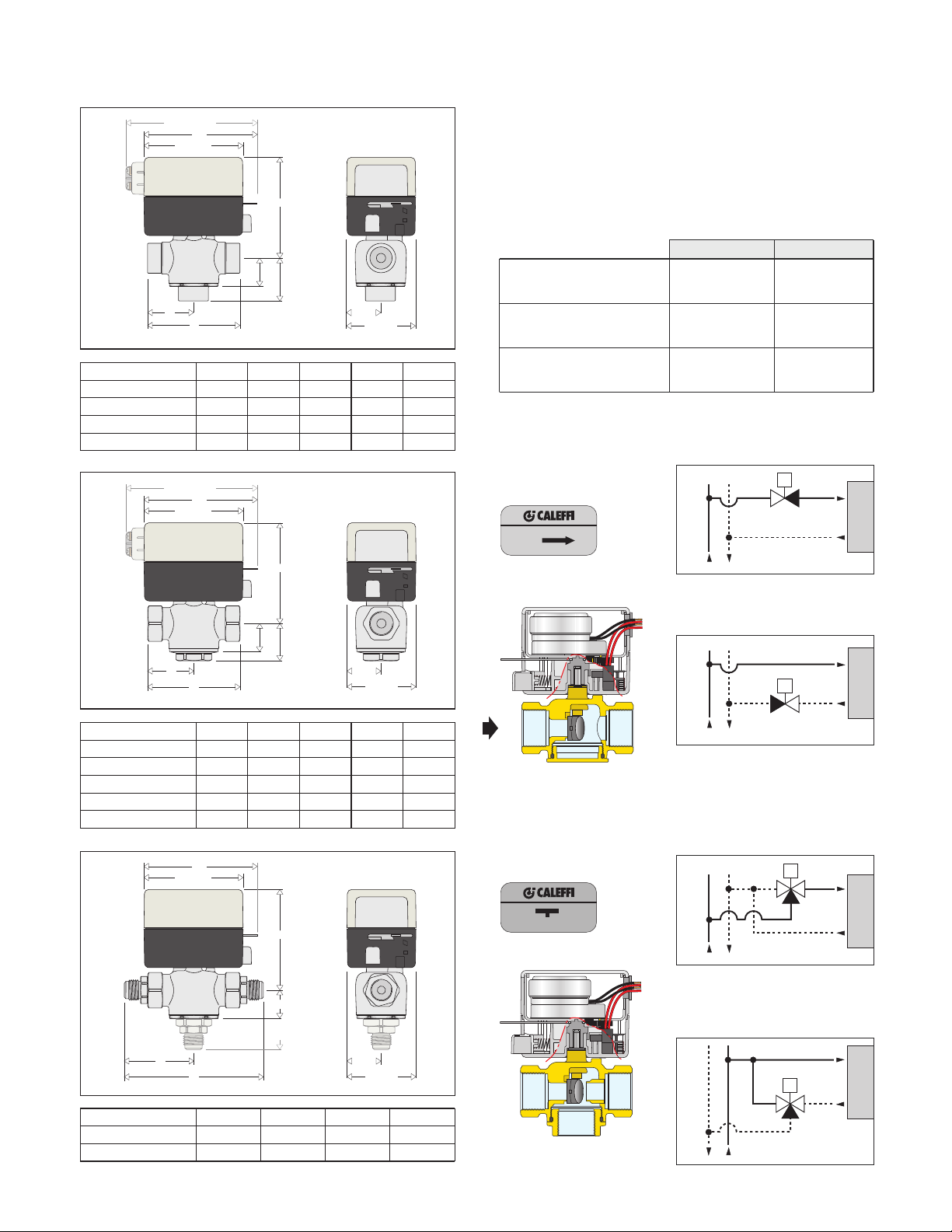
Operating principle
The Z-one actuator has a synchronous motor that winds the return
spring and moves the valve paddle to the desired position. When
power is removed the actuator spring returns the valve paddle. The
Zone actuator is equipped with or without auxiliary switch.
Operation of normally closed valve
.C. without power Port “A” closed Port “A” closed
N
.C. opened with power Port “A” opened Port “A” opened
N
.C. manually opened Port “A” open Port “A” opened
N
2-way
(with the power off,
passage A is closed)
2-way 3-way
ort “B” open
P
ort “AB” open
P
ort “B” closed
P
Port “AB” open
ort “B” opened
P
ort “AB” opened
P
-way installed on the flow side
2
2-way installed on the return side
3-way
(with the power off,
3-way installed on the flow side as a
diverting valve configuration
passage A is closed)
3-way installed on the return side as a
mixing valve configeration
Page 3

(psi) (kPa)
5.0 Cv
4.3 Kv
3/4”
1”
2.5 Cv
2.2 Kv
1/2”
3/4”
1.0 Cv
0.9 Kv
1/2”
500
200
1000
∆p (psi)
G (l/h) (
gpm
)
0.1
1
0
.
2
0
.
3
0
.5
2
3
5
1
0.5
10
2
5
2
0
1
1
0
2
3
5
2
0
3
0
0.4
4
0.1
1
0
.
2
0
.
3
0
.5
2
3
5
0.4
4
4000
2000
3.5 Cv
3.0 Kv
1/2”
3/4”
7.5 Cv
6.5 Kv
3/4”- 1”
-1 1/4”
360∞
BA
AB
(
NA
)(
NC
)
Construction details
To relay, boiler contacts
(TT) or DDC system
Thermostat
Motor
L1 (HOT)
L2
Black
Black
Red Red
Auxiliary Switch
To relay, boiler
contacts (TT)
or DDC system.
Thermostat
L1 (HOT)
L2
24 V
only
• Auxiliary switch
The actuator contains an auxiliary
microswitch to operate other devices. The
24 V actuators use a sealed reed switch,
patent pending, which has been produced
specifically for use with relays, boiler
contacts (TT) and DDC systems. It requires
no minimum current load. The 120 V - 277
V
actuators, and actuator model number
Z111000 HCS for applications requiring
greater than 400 mA, use a conventional
microswitch with silver contacts. The
auxiliary switch is activated when the valve
is 60% open or when the actuator is
manually opened.
• Manual opening (Normally closed
actuator only)
The valve can be opened manually by moving
the lever for opening it. When the power is
restored the manual control is automatically
overridden. The auxiliary switch in 24 V
actuators is tripped when the unit is put into
manual open position. This helps during start up to check if the wiring is
correct without firing the valve electrically with the thermostat.
• Easy push button
A simple push of the button makes it easy to remove it from the
body of the valve for maintenance or replacement operations.
Warning: the actuator can only be used with valve bodies Z2-Z3 series.
• Operation
The actuator is fitted with a special mechanism for gradual movement
of the valve paddle which provides smooth and quiet constant
operation. Power-on full stroke run time is 60 seconds with 6 second
power-off return time eliminating the effects of water hammer.
Installation
- The valve can be fitted either vertically or horizontally, with the
actuator in any position, except upside down.
-
If it is installed inside a encloser it is important to ensure that there
is adequate ventilation inside the encloser itself.
-
The three-way valve cannot be transformed into a two-way valve
and vice versa.
- When zone valves are installed, the direction of flow must be
observed as shown in the diagrams below.
- Two-way zone valves can be installed on both the flow and return
sides; the direction of flow indicated by the arrow on the body of
the valve must be observed.
- Three way zone valve can be fitted with NC actuator only (rotate
180° the valve body for NO application).
Wiring diagram
Flow characteristics
Connection size Flow coefficient Max. Close-off ∆P
1/2” 1.0 Cv (0.9 Kv) 75 psi (517 kPa)
1/2” - 3/4” 2.5 Cv (2.2 Kv) 50 psi (345 kPa)
1/2” - 3/4” 3.5 Cv (3.0 Kv) 30 psi (207 kPa)
3/4” - 1” 5.0 Cv (4.3 Kv) 25 psi (172 kPa)
3/4” - 1” - 1 1/4” 7.5 Cv (6.5 Kv) 20 psi (138 kPa)
Hydraulic characteristics
Terminal block
Page 4

Removal of the actuator
Fitting of the actuator
1. Move the manual open lever to the lock open position.
2. Press the push button in and pull the actuator up.
12
1. Move the manual open lever to the lock open position.
3. Verify the correct position of the valve stem into the
mating actuator hole. Move stem if required to allign.
4. Press the push button in and slide the actuator onto the
valve body, release the push button.
34
Z-one Normally Closed Valve Actuators Z-one Normally Open Valve Actuators
Code Description Code Description
Z111000 24V with auxiliary switch 18" wire Z131000 24V with auxiliary switch 18" wire
Z111000
Z116000 120V with auxiliary switch 6" wire Z133000 208V with auxiliary switch 6" wire
Z113000 208V with auxiliary switch 6" wire Z134000 230V with auxiliary switch 6" wire
Z114000 230V with auxiliary switch 6" wire Z135000 277V with auxiliary switch 6" wire
Z115000 277V with auxiliary switch 6" wire Z141000 24V without auxiliary switch 18" wire
Z151000 24V w/auxiliary switch terminal block Z146000 120V without auxiliary switch 6" wire
Z121000 24V without auxiliary switch 18" wire Z143000 208V without auxiliary switch 6" wire
Z126000 120V without auxiliary switch 6" wire Z144000 230V without auxiliary switch 6" wire
Z123000 208V without auxiliary switch 6" wire Z145000 277V without auxiliary switch 6" wire
Z124000 230V without auxiliary switch 6" wire
Z125000 277V without auxiliary switch 6" wire
HCS 24V with high current aux. switch 18" wire Z136000 120V with auxiliary switch 6" wire
Z-one 2-way Straight Through Valve Bodies Z-one 3-way Diverting Valve Bodies
Code Description Cv ∆P Code Description Cv ∆P
Z200041 Inverted Flare 1.0 75 psi Z300041 Inverted Flare 1.0 75 psi
Z200042 Inverted Flare 2.5 50 psi Z300042 Inverted Flare 2.5 50 psi
Z200043 Inverted Flare 3.5 30 psi Z300043 Inverted Flare 3.5 30 psi
Z200053 1/2" SAE Flare 3.5 30 psi Z300053 1/2" SAE Flare 3.5 30 psi
Z200411 1/2" NPT 1.0 75 psi Z300411 1/2" NPT 1.0 75 psi
Z200412 1/2" NPT 2.5 50 psi Z300412 1/2" NPT 2.5 50 psi
Z200413 1/2" NPT 3.5 30 psi Z300413 1/2" NPT 3.5 30 psi
Z200431 1/2" Sweat 1.0 75 psi Z300431 1/2" Sweat 1.0 75 psi
Z200432 1/2" Sweat 2.5 50 psi Z300432 1/2" Sweat 2.5 50 psi
Z207433 1/2" Sweat
lead-free brass 3.5 30 psi Z307433 1/2" Sweat lead-free brass 3.5 30 psi
Z200512 3/4" NPT 2.5 50 psi Z300512 3/4" NPT 2.5 50 psi
Z200513 3/4" NPT 3.5 30 psi Z300513 3/4" NPT 3.5 30 psi
Z200515 3/4" NPT 5.0 25 psi Z300515 3/4" NPT 5.0 25 psi
Z200517 3/4" NPT 7.5 20 psi Z300517 3/4" NPT 7.5 20 psi
Z200532 3/4" Sweat 2.5 50 psi Z300532 3/4" Sweat 2.5 50 psi
Z200533 3/4" Sweat 3.5 30 psi Z300533 3/4" Sweat 3.5 30 psi
Z200535 3/4" Sweat 5.0 25 psi Z300535 3/4" Sweat 5.0 25 psi
Z200537 3/4" Sweat 7.5 20 psi Z300537 3/4" Sweat 7.5 20 psi
Z207537 3/4" Sweat
lead-free brass 7.5 20 psi Z307537 3/4" Sweat lead-free brass 7.5 20 psi
Z200617 1" NPT 7.5 20 psi Z300617 1" NPT 7.5 20 psi
Z200635 1" Sweat 5.0 25 psi Z300635 1" Sweat 5.0 25 psi
Z200637 1" Sweat 7.5 20 psi Z300637 1" Sweat 7.5 20 psi
Z200737 1-1/4" Sweat 7.5 20 psi Z300737 1-1/4" Sweat 7.5 20 psi
Page 5

Z-one Normally Closed Valve Actuators & 2-way Straight Through Valve Body Combinations Matrix
actuator
ody
b
Z111000 Z116000 Z113000 Z114000 Z115000 Z151000 Z121000 Z126000 Z123000 Z124000 Z125000
Z200041 Z411041 Z416041 Z413041 Z414041 Z415041 Z451041 Z421041 Z426041 Z423041 Z424041 Z425041
Z200042 Z411042 Z416042 Z413042 Z414042 Z415042 Z451042 Z421042 Z426042 Z423042 Z424042 Z425042
Z200043 Z411043 Z416043 Z413043 Z414043 Z415043 Z451043 Z421043 Z426043 Z423043 Z424043 Z425043
Z200053 Z42 Z416053 Z413053 Z414053 Z415053 Z451053 Z32 Z426053 Z423053 Z424053 Z425053
Z200411 Z411411 Z416411 Z413411 Z414411 Z415411 Z451411 Z421411 Z426411 Z423411 Z424411 Z425411
Z200412 Z411412 Z416412 Z413412 Z414412 Z415412 Z451412 Z421412 Z426412 Z423412 Z424412 Z425412
Z200413 Z411413 Z416413 Z413413 Z414413 Z415413 Z451413 Z421413 Z426413 Z423413 Z424413 Z425413
Z200431 Z411431 Z416431 Z413431 Z414431 Z415431 Z451431 Z421431 Z426431 Z423431 Z424431 Z425431
Z200432 Z44 Z416432 Z413432 Z414432 Z415432 Z54 Z421432 Z426432 Z423432 Z424432 Z425432
Z207433 Z411433 Z416433 Z413433 Z414433 Z415433 Z451433 Z421433 Z426433 Z423433 Z424433 Z425433
Z200512 Z411512 Z416512 Z413512 Z414512 Z415512 Z451512 Z421512 Z426512 Z423512 Z424512 Z425512
Z200513 Z411513 Z416513 Z413513 Z414513 Z415513 Z451513 Z421513 Z426513 Z423513 Z424513 Z425513
Z200515 Z411515 Z416515 Z413515 Z414515 Z415515 Z451515 Z421515 Z426515 Z423515 Z424515 Z425515
Z200517 Z411517 Z416517 Z413517 Z414517 Z415517 Z451517 Z421517 Z426517 Z423517 Z424517 Z425517
Z200532 Z411532 Z416532 Z413532 Z414532 Z415532 Z451532 Z421532 Z426532 Z423532 Z424532 Z425532
Z200533 Z411533 Z416533 Z413533 Z414533 Z415533 Z451533 Z421533 Z426533 Z423533 Z424533 Z425533
Z200535 Z411535 Z416535 Z413535 Z414535 Z415535 Z451535 Z421535 Z426535 Z423535 Z424535 Z425535
Z200537 Z45 Z416537 Z413537 Z414537 Z415537 Z55 Z421537 Z426537 Z423537 Z424537 Z425537
Z200617 Z411617 Z416617 Z413617 Z414617 Z415617 Z451617 Z421617 Z426617 Z423617 Z424617 Z425617
Z200635 Z411635 Z416635 Z413635 Z414635 Z415635 Z451635 Z421635 Z426635 Z423635 Z424635 Z425635
Z200637 Z46 Z416637 Z413637 Z414637 Z415637 Z56 Z421637 Z426637 Z423637 Z424637 Z425637
Z200737 Z47 Z416737 Z413737 Z414737 Z415737 Z57 Z421737 Z426737 Z423737 Z424737 Z425737
Z-one Normally Closed Valve Actuators & 3-way Diverting Valve Body Combinations Matrix
actuator
body
Z111000 Z116000 Z113000 Z114000 Z115000 Z151000 Z121000 Z126000 Z123000 Z124000 Z125000
Z300041 Z611041 Z616041 Z613041 Z614041 Z615041 Z651041 Z621041 Z626041 Z623041 Z624041 Z625041
Z300042 Z611042 Z616042 Z613042 Z614042 Z615042 Z651042 Z621042 Z626042 Z623042 Z624042 Z625042
Z300043 Z611043 Z616043 Z613043 Z614043 Z615043 Z651043 Z621043 Z626043 Z623043 Z624043 Z625043
Z300053 Z611053 Z616053 Z613053 Z614053 Z615053 Z651053 Z621053 Z626053 Z623053 Z624053 Z625053
Z300411 Z611411 Z616411 Z613411 Z614411 Z615411 Z651411 Z621411 Z626411 Z623411 Z624411 Z625411
Z300412 Z611412 Z616412 Z613412 Z614412 Z615412 Z651412 Z621412 Z626412 Z623412 Z624412 Z625412
Z300413 Z611413 Z616413 Z613413 Z614413 Z615413 Z651413 Z621413 Z626413 Z623413 Z624413 Z625413
Z300431 Z611431 Z616431 Z613431 Z614431 Z615431 Z651431 Z621431 Z626431 Z623431 Z624431 Z625431
Z300432 Z611432 Z616432 Z613432 Z614432 Z615432 Z651432 Z621432 Z626432 Z623432 Z624432 Z625432
Z307433 Z611433 Z616433 Z613433 Z614433 Z615433 Z651433 Z621433 Z626433 Z623433 Z624433 Z625433
Z300512 Z611512 Z616512 Z613512 Z614512 Z615512 Z651512 Z621512 Z626512 Z623512 Z624512 Z625512
Z300513 Z611513 Z616513 Z613513 Z614513 Z615513 Z651513 Z621513 Z626513 Z623513 Z624513 Z625513
Z300515 Z611515 Z616515 Z613515 Z614515 Z615515 Z651515 Z621515 Z626515 Z623515 Z624515 Z625515
Z300517 Z611517 Z616517 Z613517 Z614517 Z615517 Z651517 Z621517 Z626517 Z623517 Z624517 Z625517
Z300532 Z611532 Z616532 Z613532 Z614532 Z615532 Z651532 Z621532 Z626532 Z623532 Z624532 Z625532
Z300533 Z611533 Z616533 Z613533 Z614533 Z615533 Z651533 Z621533 Z626533 Z623533 Z624533 Z625533
Z300535 Z611535 Z616535 Z613535 Z614535 Z615535 Z651535 Z621535 Z626535 Z623535 Z624535 Z625535
Z300537 Z611537 Z616537 Z613537 Z614537 Z615537 Z651537 Z621537 Z626537 Z623537 Z624537 Z625537
Z300617 Z611617 Z616617 Z613617 Z614617 Z615617 Z651617 Z621617 Z626617 Z623617 Z624617 Z625617
Z300635 Z611635 Z616635 Z613635 Z614635 Z615635 Z651635 Z621635 Z626635 Z623635 Z624635 Z625635
Z300637 Z611637 Z616637 Z613637 Z614637 Z615637 Z651637 Z621637 Z626637 Z623637 Z624637 Z625637
Z300737 Z611737 Z616737 Z613737 Z614737 Z615737 Z651737 Z621737 Z626737 Z623737 Z624737 Z625737
Page 6

CALEFFI
Z-one Normally Open Valve Actuators & 2-way Straight Thru Valve Body Combinations Matrix
actuator
ody
b
Z200041 Z431041 Z436041 Z433041 Z434041 Z435041 Z441041 Z446041 Z443041 Z444041 Z445041
Z200042 Z431042 Z436042 Z433042 Z434042 Z435042 Z441042 Z446042 Z443042 Z444042 Z445042
Z200043 Z431043 Z436043 Z433043 Z434043 Z435043 Z441043 Z446043 Z443043 Z444043 Z445043
Z200053 Z431053 Z436053 Z433053 Z434053 Z435043 Z441053 Z446053 Z443053 Z444053 Z445053
200411 Z431411 Z436411 Z433411 Z434411 Z435411 Z441411 Z446411 Z443411 Z444411 Z445411
Z
Z200412 Z431412 Z436412 Z433412 Z434412 Z435412 Z441412 Z446412 Z443412 Z444412 Z445412
Z200413 Z431413 Z436413 Z433413 Z434413 Z435413 Z441413 Z446413 Z443413 Z444413 Z445413
Z200431 Z431431 Z436431 Z433431 Z434431 Z435431 Z441431 Z446431 Z443431 Z444431 Z445431
Z200432 Z431432 Z436432 Z433432 Z434432 Z435432 Z441432 Z446432 Z443432 Z444432 Z445432
Z207433 Z431433 Z436433 Z433433 Z434433 Z435433 Z441433 Z446433 Z443433 Z444433 Z445433
Z200512 Z431512 Z436512 Z433512 Z434512 Z435512 Z441512 Z446512 Z443512 Z444512 Z445512
Z200513 Z431513 Z436513 Z433513 Z434513 Z435513 Z441513 Z446513 Z443513 Z444513 Z445513
Z200515 Z431515 Z436515 Z433515 Z434515 Z435515 Z441515 Z446515 Z443515 Z444515 Z445515
Z200517 Z431517 Z436517 Z433517 Z434517 Z435517 Z441517 Z446517 Z443517 Z444517 Z445517
Z200532 Z431532 Z436532 Z433532 Z434532 Z435532 Z441532 Z446532 Z443532 Z444532 Z445532
Z200533 Z431533 Z436533 Z433533 Z434533 Z435533 Z441533 Z446533 Z443533 Z444533 Z445533
Z200535 Z431535 Z436535 Z433535 Z434535 Z435535 Z441535 Z446535 Z443535 Z444535 Z445535
Z200537 Z431537 Z436537 Z433537 Z434537 Z435537 Z441537 Z446537 Z443537 Z444537 Z445537
Z200617 Z431617 Z436617 Z433617 Z434617 Z435617 Z441617 Z446617 Z443617 Z444617 Z445617
Z200635 Z431635 Z436635 Z433635 Z434635 Z435635 Z441635 Z446635 Z443635 Z444635 Z445635
Z200637 Z431637 Z436637 Z433637 Z434637 Z435637 Z441637 Z446637 Z443637 Z444637 Z445637
Z200737 Z431737 Z436737 Z433737 Z434737 Z435737 Z441737 Z446737 Z443737 Z444737 Z445737
Z131000 Z136000 Z133000 Z134000 Z135000 Z141000 Z146000 Z143000 Z144000 Z145000
To use the above tables follow this example: Select actuator Z131000 from the top row combined with body Z200041 from left column to
create the combination Z431041.
SPECIFICATION SUMMARIES
The Z-one series two-position spring return with removable actuator zone valve. Z1 series actuator is NC or NO 24 V to
277 V 50/60 Hz 6.5 W 7 VA, with or without auxiliary switch {(24 V: 0.4A max, 24 V) (120-277 V: 5.0A, 250 V)}, Auxiliary
switch for 24 V actuator is a sealed reed switch requiring no minumum current load, includes leads or terminal block (24
V only); operating temperature from 32 ~ 104°F for 24 V and 120 V actuators; 32 ~ 170 deg F for 208 V, 230 V, 277 V
actuators. Z2 (2-way) series and Z3 (3-way) series are forged brass (2-way and 3-way 1/2" and 3/4" sweat valve bodies
pn Zn07433 and Zn07537 are lead-free certified by IAPMO R&T) valve body rated at 300 psi, temperature rated 32 ~
240°F. Valve stem stainless steel, seals EPDM, flows from 1.0 ~ 7.5 Cv connections size from 1/2” to 1 1/4”, sweat, NPT
female threads, SAE flare and inverted flare. Actuator approved for UL873, including air plenums and ducts rating per UL
1995 section 18.
We reserve the right to change our products and their relevant technical data, contained in this publication, at any time and without prior notice.
Caleffi North America, Inc.
3883 West Milwaukee Road / Milwaukee, WI 53208
Tel: 414.238.2360 / Fax: 414.238.2366 / www.caleffi.us
© Copyright 2011 Caleffi
 Loading...