

Page 1
www.caleffi.com N A 1 0 0 7 3 .04
Z-one™ Z1, Z2, Z3 Series
Function
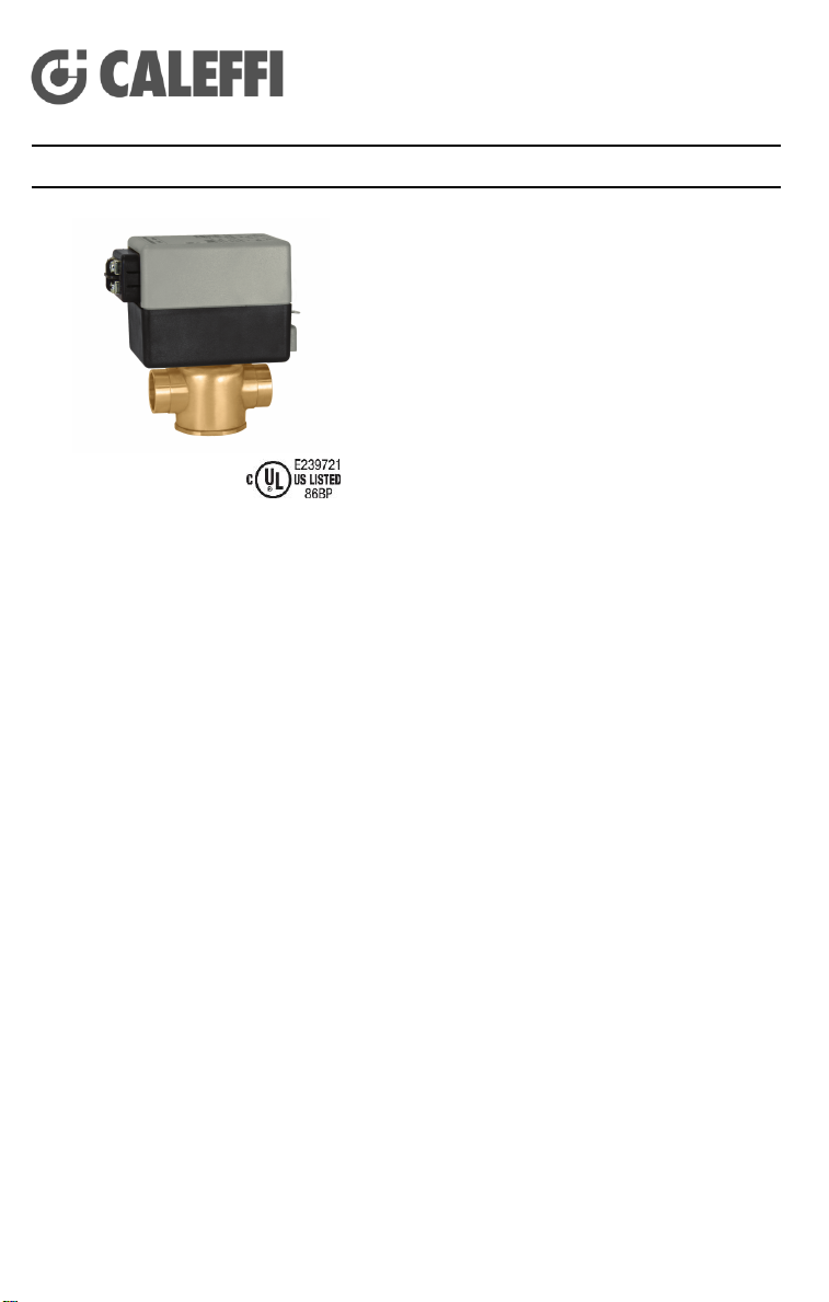
The Z-one, a two-position spring return zone valve,
is used in heating and air-conditioning systems.
The Z-one series consist of a Z1 actuator which is
easily attached to a Z2 (2-way) or Z3 (3-way) valve
body. Z1 actuator is equipped with or without
auxiliary switch.
The Z-one actuator has a synchronous motor that
winds the return spring and moves the valve paddle
to the desired position. When power is removed the
actuator spring returns the valve paddle. 24V
actuators use a sealed reed switch for end switch,
requiring no minimum current load.
US Patent 7,048,251
Technical Characteristics of Body
Material: - body: forged brass (optional lead-free brass, see page 6 for
- seat: machined brass
- stem: stainless steel
- two o-ring seals EPDM
- paddle EPDM
Medium: water and glycol
Maximum percent of glycol: 50%
Temperature range: 32 to 240°F (0 – 115°C)
Max. static pressure: 15 psi (1 bar) steam
Connection: -press (lay length: 3-5/8”; overall length 5-5/8”) ½”, ¾” 1”
-sweat ½”, ¾” 1” & 1 ¼”
- NPT ½”, ¾” & 1”
- SAE flare ½”
- inverted flare ½”, ¾” & 1” sweat, fittings separate
Lay length (press connections): size ½ inch: 3 ½”
Technical Characteristics of Actuator
Material: - base and cover: polycarbonate
- base plate: aluminum
Motor: - voltage: 24 VAC 50/60 Hz Class 2
- current draw: 24 VAC – 300 mA
certification statement)
300 psi (20 bar)
size ¾ inch: 3 5/8”
size ¾ inch (PL): 5”
size 1 inch: 4 1/8”
120 VAC 50/60 Hz
208 VAC 50/60 Hz
230 VAC 50/60 Hz
277 VAC 50/60 Hz
120 VAC – 55 mA
208 VAC – 30 mA
230 VAC – 25 mA
277 VAC – 20 mA
Page 2
Wire lead length: 6” (15cm), 24V only -18” (45cm)
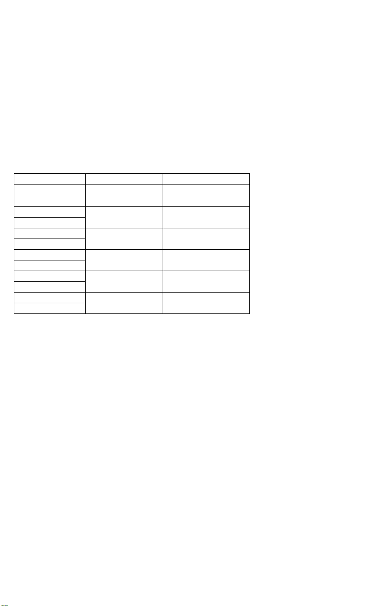
Connection size
Flow Coefficient
Max. Close-off P
1/2"
1.0 Cv (0.9 kv)
75 PSI (517 kPa)
1/2"
2.5 Cv (2.2 kv)
50 PSI (345 kPa)
3/4"
1/2"
3.5 Cv (3.0 kv)
30 PSI (207 kPa)
3/4"
3/4"
5.0 Cv (4.3 kv)
25 PSI (172 kPa)
1"
3/4"
7.5 Cv (6.5 kv)
20 PSI (138 kPa)
1"
1"
7.5 Cv (6.5 kv)
20 PSI (138 kPa)
1 1/4"
Power requirements: 5.0 W, 7 VA
Ambient temperature range: 32 - 125ºF (170ºF optional)
Auxiliary switch: 24 VAC: 0.0 A min,
120-277 VAC:
0.25A min, 5A max, 250 V
Humidity: 95% non-condensing
Approvals: UL873, cUL Listed & CE
UL 1995 sec. 18 (air plenum & ducts)
Normally Open Actuators must be powered down during off-season.
0.4 A max, 24 V
Flow Characteristics
Page 3
2-way installed on the supply
Installation
2-way installed on the return
A
B
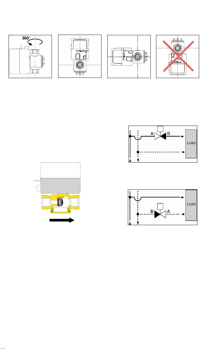
The valve can be installed vertically or horizontally, but not turned upside down.
- A 3-way valve cannot be transformed into a 2-way valve and vice versa.
- The flow is from A to B (see diagram below) and must be installed so the paddle
closes against the direction of flow as indicated in the following diagrams.
- The 2-way valves can be installed on the
supply or on the return; for correct
installation it is necessary to respect the
direction of flow indicated from the arrow
on the body valve.
2-way valve with normally closed actuator
Page 4
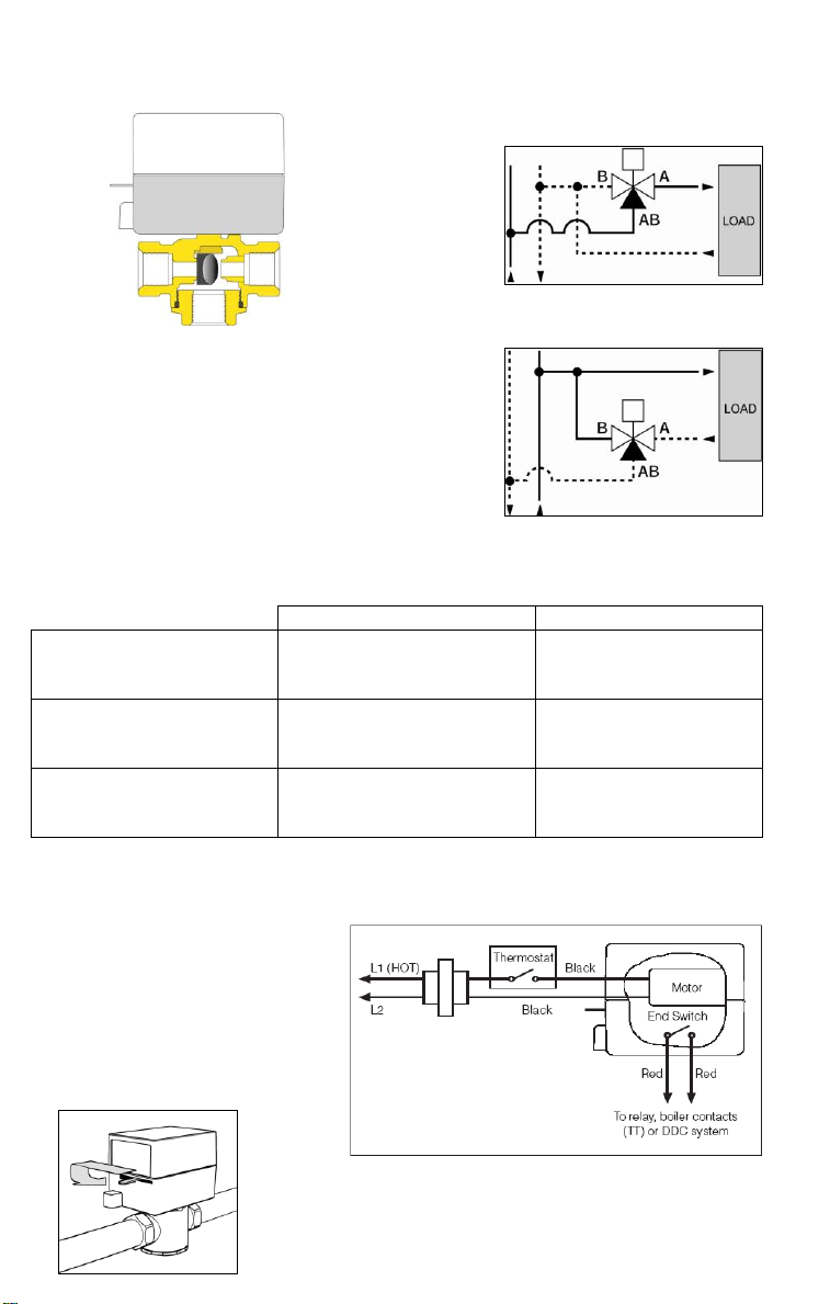
3-way valve with normally closed actuator
2-way
3-way
N.C. without power
Port “A” closed
Port “A” closed
Port “B” opened
Port “AB” opened
N.C. opened with power
Port “A” opened
Port “A” opened
Port “B” closed
Port “AB” opened
N.C. manually opened
Port “A” opened
Port “A” opened
Port “B” opened
Port “AB” opened
(NC) A
B (NO)
AB
The manual opening is
achieved by moving the
manual opening lever to
the locked position. When
power is applied, the
manual lever unlocks
automatically.
(Note: 3-way uses only normally closed actuator)
Operation of Normally Closed Valve
3-way installed on the supply
in diverting configuration
3-way installed on the return
Manual Open (NC act only) Wiring Diagram
Page 5
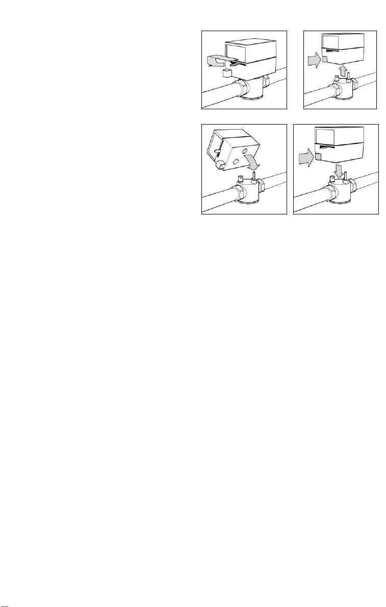
Removing the Actuator
1 2 3
4
1. Move the manual open lever to the
lock open position.
2. Press the push button in and pull the
actuator up.
Installing the Actuator
1. Move the manual open lever to the
lock open position.
3. Verify the correct position of the valve
stem into the mating actuator hole.
Rotate stem if required to align.
4. Press the push button in and slide the
actuator onto the valve body, release
the push button.
Page 6
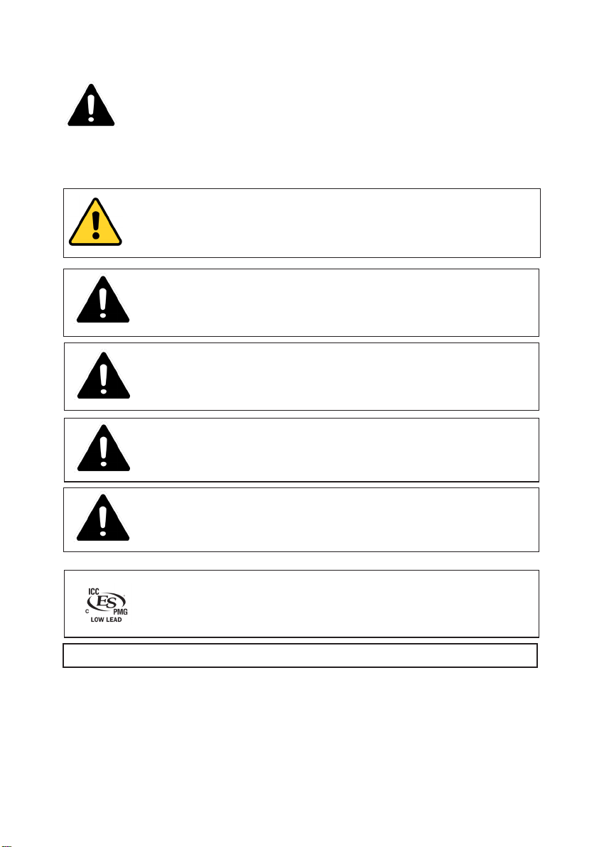
SAFETY INSTRUCTION
This safety alert symbol will be used in this manual to draw attention to safety related instructions.
When used, the safety alert symbol means ATTENTION! BECOME ALER T! YOUR SAFETY IS INVOLVED!
FAILURE TO FOLLOW THESE INSTRUC TIONS M AY RESULT IN A SAFETY HAZARD.
WARNING: This product can expose you to chemicals including lead, which is known
to the State of California to cause cancer and birth defects or other reproductive
harm. For more information go to www.P65Warnings.ca.gov.
CAUTION: All work must be performed by qualified personnel trained in the
proper application, installation, and maintenance of systems in accordance
with all applicable codes and ordinances.
CAUTION: Over-tightening and breakage can occur with the use of Teflon
pipe joint compounds. Teflon provides lubricity so that care must be exercised
not to over-tighten joints. Failure to follow these instructions could result in
property damage and/or personal injury.
CAUTION: System fluids are under pressure or temperature can be
hazardous. Be sure the pressure has been reduced to zero and the system
temperature is below 100ºF (38ºC). Failure to follow these instructions could
result in property damage and/or personal injury.
CAUTION: Avoid locations with excessive moisture, explosive vapors,
corrosive fumes or vibration. Failure to follow these instructions could result
in
stress corrosion resulting in property damage and/or personal injury.
Caleffi shall not be liable for damages resulting from stress corrosion, misapplication or misuse of it products.
Approval for low-lead brass: NSF/ANSI 372-2011, Drinking Water System
Components-Lead Content Reduction of Lead in Drinking Water Act,
California Health and Safety Code 116875 S.3874, Reduction of Lead in
Drinking Water Act, certifed by ICC-ES, file PMG-1360.
Leave this manual for the user.
Page 7
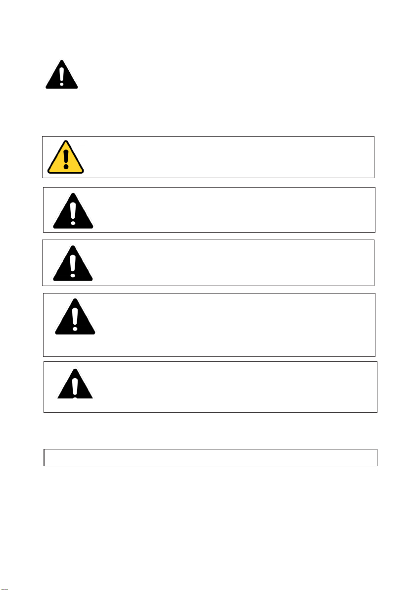
CONSIGNE DE SÉCURITÉ
Ce symbole d'avertissement servira dans ce manuel à attirer l'attention sur la sécurité concernant
instructions. Lorsqu'il est utilisé, ce symbole signifie.
ATTENTION! DEVENEZ ALERTE ! VOTRE SÉCURITÉ EST EN JEU ! NE PAS SUIVRE CES
INSTRUCTIONS PEUT PROVOQUER UN RISQUE DE SECURITE.
AVERTISSEMENT:
Ce produit peut vous exposer à des produits chimiques comme
le plomb, qui est connu dans l’État de Californie pour causer le cancer, dommages à
la naissance ou autre. Pour plus d’informations rendez-vous www.P65Warnings.ca.gov.
ATTENTION: Tous les travaux doivent être effectués par du personnel
qualifié formé à la bonne application, installation et maintenance des systèmes
conformément aux codes et règlements locaux.
ATTENTION: Un serrage excessif et la rupture peuvent se produire avec
l’utilisation de raccords filetés de tuyaux téflon. Téflon fournit un pouvoir
lubrifiant afin qu’il doit être prudent pour ne pas trop serrer les joints. Suivre
ces instructions peut entraîner de propriété dommages et/ou des blessures.
ATTENTION: Système fluides sont sous pression ou de température peut
s’avérer dangereuse. Veillez à ce que la pression a été réduite à zéro et
la température du système est inférieure à 100ºF (38 ° c). De suivre ces
instructions peut entraîner des dommages matériels et/ou des blessures
corporelles graves.
ATTENTION: Évitez les endroits avec une humidité excessive, les vapeurs
explosives, les vapeurs corrosives ou les vibrations. Suivre ces instructions
peut entraîner de la corrosion sous tension, ce qui entraîne des dommages
matériels ou corporels.
Caleffi décline toute responsabilité pour dommages résultant de la corrosion, une mauvaise utilisation ou utilisation abusive de
celui-ci produits.
LAISSEZ CE MANUEL AVEC L’UTILISATEUR
Page 8

5-14-18
____________________________________________________
Caleffi North America, Inc.
3883 W. Milwaukee Road / Milwaukee, WI 53208
Tel: 414.238.2360 / Fax: 414.238.2366 / www.caleffi.com
© Copyright 2018 Caleffi North America, Inc.
 Loading...